EP0143225B1 - Mélangeur équilibré aux micro-ondes - Google Patents
Mélangeur équilibré aux micro-ondes Download PDFInfo
- Publication number
- EP0143225B1 EP0143225B1 EP84110802A EP84110802A EP0143225B1 EP 0143225 B1 EP0143225 B1 EP 0143225B1 EP 84110802 A EP84110802 A EP 84110802A EP 84110802 A EP84110802 A EP 84110802A EP 0143225 B1 EP0143225 B1 EP 0143225B1
- Authority
- EP
- European Patent Office
- Prior art keywords
- waveguide
- converter
- ridged
- filter
- frequency
- Prior art date
- Legal status (The legal status is an assumption and is not a legal conclusion. Google has not performed a legal analysis and makes no representation as to the accuracy of the status listed.)
- Expired - Lifetime
Links
Images


Classifications
-
- H—ELECTRICITY
- H03—ELECTRONIC CIRCUITRY
- H03D—DEMODULATION OR TRANSFERENCE OF MODULATION FROM ONE CARRIER TO ANOTHER
- H03D9/00—Demodulation or transference of modulation of modulated electromagnetic waves
- H03D9/06—Transference of modulation using distributed inductance and capacitance
- H03D9/0608—Transference of modulation using distributed inductance and capacitance by means of diodes
- H03D9/0616—Transference of modulation using distributed inductance and capacitance by means of diodes mounted in a hollow waveguide
Definitions
- the invention relates to a microwave push-pull frequency converter according to the preamble of claim 1.
- a microwave push-pull frequency converter is known (special print from NTZ, vol. 33, (1980), book 9, pages 590 to 591).
- Low-loss direct converters for television broadcasting satellites are constructed using waveguide technology. Such a converter directly converts five frequency-modulated received signals within a 400 MHz wide band of 19 GHz into a transmit signal of 12 GHz. Possible other frequency combinations for these direct converters are e.g. 6 to 4, 14 to 4, 14 to 12, 30 to 4, 30 to 20 or 30 to 12 GHz.
- Semiconductor mixers must meet very high requirements with regard to undesired mixed products for space equipment. They are therefore connected to input and output filters.
- a waveguide low-pass filter is known from US-A-3,949,327, consisting of capacitive webs and inductive sections connecting the latter.
- the inductive sections are designed for evanescent mode operation in the pass band and the capacitive webs for the propagation of only one wave type in the pass band and in the first stop band.
- the object of the invention is to provide a microwave push-pull frequency converter in waveguide technology according to the preamble of claim 1, the input and output frequencies are relatively far apart, in particular their ratio exceeds the value 1.5, and which has favorable behavior with regard to insertion loss and suppression of mixed products .
- the waveguide filter for the microwave signal of low frequency enables good low-pass behavior to be achieved.
- the equivalent circuit of this filter essentially only has transverse capacitances and series inductors.
- the filter impedance is chosen to be relatively low, no additional transformation is required to couple the filter to the ridge waveguide to the mixing module.
- this choice of low-pass impedance (approx. 80 ohms) and the introduction of tuning screws in the webs result in a small overall length.
- the mixing module allows high and low frequency microwave signals to pass through in a clear mode, for example the H lo wave.
- the converter according to the invention is qualified in space.
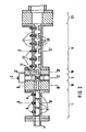
- a microwave push-pull frequency converter is shown as a down mixer using a block diagram.
- a 30 GHz input signal f E microwave signal of high frequency
- the mixing module 2 contains two semiconductor mixing elements 3 and 4, for example GaAs Schottky diodes, which are connected for push-pull operation.
- the semiconductor mixing elements 3 and 4 are supplied with an oscillator frequency f o via an oscillator filter 5.
- the oscillator frequency f o is selected with respect to the input frequency f E so that a frequency conversion to 12 GHz takes place.
- This 12 GHz signal f A (low frequency microwave signal) is freed from undesired mixed products by means of the filter 6.
- the filter 6, as will be explained in more detail below, consists of web waveguide sections with capacitive behavior coupled by means of blocking waveguide sections.
- the cross section through the converter, Fig. 2 shows the structure in detail.
- a waveguide connector 7 for 30 GHz is connected on the input side to the filter 1.
- the filter 1 consists of a three-circuit Tschebyscheff band filter in rectangular waveguide technology for the H lo wave.
- the coupling is carried out by means of inductive symmetrical diaphragms 8.
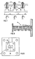
- Three capacitive tuning pins 9 are arranged for tuning, each in the middle between two diaphragms. These tuning pins 9 consist of simple tuning screws which are embedded in the upper broad side of the waveguide, cf. Sectional drawing Fig. 3.
- the corners of the waveguide filter 1 are rounded for manufacturing reasons - quasi elliptical.
- a web waveguide piece 10 connects to the filter 1 for the 30 GHz signal and establishes the connection between this filter and the mixing module 2.
- the ridge waveguide piece 10 is shown in section in FIG. 4.
- the two webs 11 are located on the broad sides of the rectangular waveguide for the H lo wave.
- the output impedance that the filter 1 has for the 30 GHz signal at 12 GHz is to be transformed into the level of the semiconductor mixing elements 3 and 4 by the ridge waveguide piece 10 between the mixing module 2 and the filter 1 in such a way that an idle state in this level (diode level) for the 12 GHz signal.
- the length of the ridge waveguide piece 10 corresponds to approximately A n / 8, which is approximately 6 mm at 30 GHz signal frequency, the exact length depending on the input impedance of the filter 1 for the 12 GHz signal.
- the mixing module 2 is constructed as a three-port, two ports (feed and discharge of 30 GHz 12 GHz signal of the) are connected by a ridge waveguide and the third port for supplying the oscillator frequency f o in coaxial technique is performed.
- the mixing module 2 accommodates two semiconductor mixing elements 3 and 4 GaAs Schottky diodes arranged one above the other - in micropill housings. The mutually rejecting ends of the diodes are fixed by fastening devices - gold bellows 12. The gold bellows 12 are introduced into the mixing module housing via bores 13 and are soldered there.
- the oscillator frequency f o is supplied to the diodes 3 and 4 galvanically.
- a bore 14 is provided through which an inner conductor 15 protrudes. One end of the inner conductor 15 is connected to the facing ends of the diodes 3 and 4.
- the other end of the inner conductor 15 is connected to the inner conductor 16 of a coaxial pot circle 17 (capacitively shortened A resonator).
- the oscillator frequency f o is laterally coupled into this pot circle 17.
- the pot circle 17 serves as a filter 5 for the oscillator frequency f o .
- the 30 GHz microwave signal is converted into the 12 GHz range (microwave signal of low frequency) by means of the oscillator frequency f o .
- a ridge waveguide piece 18, which establishes the connection between the filter 6 for the low-frequency microwave signal and the mixing module 2 is connected to the mixing module 2 in the waveguide technology.
- the cross section of the ridge waveguide section 18 corresponds to the cross section of the ridge waveguide section 10.
- the input impedance of the 12 GHz filter 6 is to be transformed into the diode level by the ridge waveguide section 18 between the mixing module 2 and the 12 GHz filter 6 in such a way that there is an open circuit for the 30 GHz signal.
- the length of the bridge piece is about A H / 4. This is about 4.5 mm at 30 GHz. The exact length depends on the input impedance of the following filter for the 30 GHz signal.
- the adjoining filter 6 for the microwave signal of low frequency consists of ridge waveguide sections 20 which are coupled by blocking waveguide sections 21 (cut-off waveguide).
- the ridge waveguide sections 20 can be tuned via tuning pins 22. These tuning pins 22, as shown in particular in the sectional view in FIG. 6, consist of simple tuning screws. They are each introduced from above in the middle of the broad side of the resonator.
- the ridge waveguide sections 20 with the tuning screws 22 represent tunable transverse capacitances C.
- the blocking waveguide sections 21 represent longitudinal inductances L.
- the lengths b are the smallest at the ends of the filter 6 and the greatest in the middle of the filter.
- the webs are 4 mm wide and 3 mm high. They are 2 mm apart.
- a single-stage or multi-stage ⁇ / 4 waveguide transformer 23 is located at the end of the filter 6 remote from the mixing module.
Landscapes
- Physics & Mathematics (AREA)
- Electromagnetism (AREA)
- Engineering & Computer Science (AREA)
- Power Engineering (AREA)
- Control Of Motors That Do Not Use Commutators (AREA)
- Stabilization Of Oscillater, Synchronisation, Frequency Synthesizers (AREA)
Claims (6)
Applications Claiming Priority (2)
| Application Number | Priority Date | Filing Date | Title |
|---|---|---|---|
| DE3342400 | 1983-11-24 | ||
| DE3342400 | 1983-11-24 |
Publications (3)
| Publication Number | Publication Date |
|---|---|
| EP0143225A2 EP0143225A2 (fr) | 1985-06-05 |
| EP0143225A3 EP0143225A3 (en) | 1987-08-19 |
| EP0143225B1 true EP0143225B1 (fr) | 1990-11-28 |
Family
ID=6215087
Family Applications (1)
| Application Number | Title | Priority Date | Filing Date |
|---|---|---|---|
| EP84110802A Expired - Lifetime EP0143225B1 (fr) | 1983-11-24 | 1984-09-11 | Mélangeur équilibré aux micro-ondes |
Country Status (5)
| Country | Link |
|---|---|
| US (1) | US4661999A (fr) |
| EP (1) | EP0143225B1 (fr) |
| JP (1) | JPS60134504A (fr) |
| CA (1) | CA1222550A (fr) |
| DE (1) | DE3483681D1 (fr) |
Families Citing this family (6)
| Publication number | Priority date | Publication date | Assignee | Title |
|---|---|---|---|---|
| US5156990A (en) * | 1986-07-23 | 1992-10-20 | Texas Instruments Incorporated | Floating-gate memory cell with tailored doping profile |
| DE3737671A1 (de) * | 1987-11-06 | 1989-05-24 | Ant Nachrichtentech | Mikrowellen-gegentaktmischer |
| US5125110A (en) * | 1990-10-17 | 1992-06-23 | Valentine Research, Inc. | Microstripline microwave mixer using waveguide filter |
| DE19736367A1 (de) * | 1997-08-21 | 1999-02-25 | Bosch Gmbh Robert | Hohlleiterfilter |
| US20060006966A1 (en) * | 2004-07-08 | 2006-01-12 | Qinghua Kang | Electronically tunable ridged waveguide cavity filter and method of manufacture therefore |
| US9899716B1 (en) * | 2015-03-01 | 2018-02-20 | Telefonaktiebolaget Lm Ericsson (Publ) | Waveguide E-plane filter |
Family Cites Families (5)
| Publication number | Priority date | Publication date | Assignee | Title |
|---|---|---|---|---|
| US3638126A (en) * | 1969-08-21 | 1972-01-25 | George Ctirad Spacek | High-frequency converter |
| US3949327A (en) * | 1974-08-01 | 1976-04-06 | Sage Laboratories, Inc. | Waveguide low pass filter |
| GB2006539A (en) * | 1977-05-25 | 1979-05-02 | Marconi Co Ltd | Dual Evanescent Mode Waveguide Filter |
| US4348773A (en) * | 1980-01-15 | 1982-09-07 | Ignazio Caroli | Microwave receiver converters having a hybrid waveguide structure |
| DE3040506C2 (de) * | 1980-10-28 | 1984-09-27 | ANT Nachrichtentechnik GmbH, 7150 Backnang | Demodulator für phasendifferenzmodulierte Signale |
-
1984
- 1984-09-11 DE DE8484110802T patent/DE3483681D1/de not_active Expired - Lifetime
- 1984-09-11 EP EP84110802A patent/EP0143225B1/fr not_active Expired - Lifetime
- 1984-11-21 JP JP59244738A patent/JPS60134504A/ja active Pending
- 1984-11-21 US US06/673,999 patent/US4661999A/en not_active Expired - Fee Related
- 1984-11-23 CA CA000468482A patent/CA1222550A/fr not_active Expired
Also Published As
| Publication number | Publication date |
|---|---|
| US4661999A (en) | 1987-04-28 |
| JPS60134504A (ja) | 1985-07-17 |
| CA1222550A (fr) | 1987-06-02 |
| EP0143225A2 (fr) | 1985-06-05 |
| EP0143225A3 (en) | 1987-08-19 |
| DE3483681D1 (de) | 1991-01-10 |
Similar Documents
| Publication | Publication Date | Title |
|---|---|---|
| DE69730389T2 (de) | Tiefpassfilter mit richtkoppler und tragbares telefon damit | |
| DE69924168T2 (de) | Bandpassfilter, Duplexer, Hochfrequenzmodul und Kommunikationsgerät | |
| DE68927773T2 (de) | Mikrowellenfilter | |
| DE19729761A1 (de) | Symmetrieübertrager | |
| WO1996003801A1 (fr) | Melangeur d'ondes millimetriques realise par fenetrage | |
| DE19853484A1 (de) | Hochfrequente Schalteinrichtung | |
| EP0101611B1 (fr) | Module d'émission-réception | |
| DE69624377T2 (de) | Antennenverstärker | |
| DE69935290T2 (de) | Dielektrisches Filter, dielektrisches Verbundfilter, Antennenweiche und Kommunikationsgerät | |
| EP1388206B1 (fr) | Dispositif filtre destine a des systemes de lignes symetriques et asymetriques | |
| EP0143225B1 (fr) | Mélangeur équilibré aux micro-ondes | |
| DE69706170T2 (de) | Frequenzumsetzer für millimeterwellen | |
| DE68917373T2 (de) | Magnetisch abstimmbares Bandpassfilter. | |
| DE2322549B2 (de) | Antennenweiche | |
| DE3324540C2 (de) | Breitbandiger Mikrowellenverstärker | |
| DE10305379A1 (de) | Frontendschaltung | |
| DE2733888C2 (de) | Schaltung zum Aufteilen oder Zusammenführen von Hochfrequenzleistung | |
| DE2541569C2 (de) | Frequenzabhängiges Dämpfungsglied | |
| DE3587437T2 (de) | Elektrische Hochfrequenzschaltung. | |
| DE69124013T2 (de) | Dreifacher Gegentakt-Breitbandmischer mit hoher Frequenz | |
| DE19941881A1 (de) | Dielektrisches Filter, dielektrischer Duplexer und Sende-Empfangs-Vorrichtung | |
| DE69700883T2 (de) | Subharmonischer frequenzkonverter für anwendungen im millimeterbereich | |
| DE68910719T2 (de) | Mikrowellensperrfilter in Mikrostreifenausführung. | |
| DE3637827C2 (de) | Koplanarer Gegentakt-Hohlleiter-Mischer | |
| DE69000844T2 (de) | Mikrowellen-frequenzumsetzer. |
Legal Events
| Date | Code | Title | Description |
|---|---|---|---|
| PUAI | Public reference made under article 153(3) epc to a published international application that has entered the european phase |
Free format text: ORIGINAL CODE: 0009012 |
|
| AK | Designated contracting states |
Designated state(s): DE FR GB IT |
|
| RTI1 | Title (correction) | ||
| PUAL | Search report despatched |
Free format text: ORIGINAL CODE: 0009013 |
|
| AK | Designated contracting states |
Kind code of ref document: A3 Designated state(s): DE FR GB IT |
|
| 17P | Request for examination filed |
Effective date: 19870706 |
|
| 17Q | First examination report despatched |
Effective date: 19890828 |
|
| GRAA | (expected) grant |
Free format text: ORIGINAL CODE: 0009210 |
|
| ITF | It: translation for a ep patent filed | ||
| AK | Designated contracting states |
Kind code of ref document: B1 Designated state(s): DE FR GB IT |
|
| GBT | Gb: translation of ep patent filed (gb section 77(6)(a)/1977) | ||
| REF | Corresponds to: |
Ref document number: 3483681 Country of ref document: DE Date of ref document: 19910110 |
|
| ET | Fr: translation filed | ||
| REG | Reference to a national code |
Ref country code: GB Ref legal event code: 746 |
|
| REG | Reference to a national code |
Ref country code: FR Ref legal event code: DL |
|
| PLBE | No opposition filed within time limit |
Free format text: ORIGINAL CODE: 0009261 |
|
| STAA | Information on the status of an ep patent application or granted ep patent |
Free format text: STATUS: NO OPPOSITION FILED WITHIN TIME LIMIT |
|
| ITTA | It: last paid annual fee | ||
| 26N | No opposition filed | ||
| PGFP | Annual fee paid to national office [announced via postgrant information from national office to epo] |
Ref country code: DE Payment date: 19941118 Year of fee payment: 11 |
|
| PGFP | Annual fee paid to national office [announced via postgrant information from national office to epo] |
Ref country code: GB Payment date: 19950818 Year of fee payment: 12 |
|
| PGFP | Annual fee paid to national office [announced via postgrant information from national office to epo] |
Ref country code: FR Payment date: 19950918 Year of fee payment: 12 |
|
| PG25 | Lapsed in a contracting state [announced via postgrant information from national office to epo] |
Ref country code: DE Effective date: 19960601 |
|
| PG25 | Lapsed in a contracting state [announced via postgrant information from national office to epo] |
Ref country code: GB Effective date: 19960911 |
|
| PG25 | Lapsed in a contracting state [announced via postgrant information from national office to epo] |
Ref country code: FR Effective date: 19960930 |
|
| GBPC | Gb: european patent ceased through non-payment of renewal fee |
Effective date: 19960911 |
|
| REG | Reference to a national code |
Ref country code: FR Ref legal event code: ST |
|
| REG | Reference to a national code |
Ref country code: FR Ref legal event code: ST |