EP0143237A1 - Ferrure de poignée pour ferrures de tringles coulissantes de fenêtres, portes ou similaires - Google Patents
Ferrure de poignée pour ferrures de tringles coulissantes de fenêtres, portes ou similaires Download PDFInfo
- Publication number
- EP0143237A1 EP0143237A1 EP84111109A EP84111109A EP0143237A1 EP 0143237 A1 EP0143237 A1 EP 0143237A1 EP 84111109 A EP84111109 A EP 84111109A EP 84111109 A EP84111109 A EP 84111109A EP 0143237 A1 EP0143237 A1 EP 0143237A1
- Authority
- EP
- European Patent Office
- Prior art keywords
- handle
- locking
- screw
- slide
- plate
- Prior art date
- Legal status (The legal status is an assumption and is not a legal conclusion. Google has not performed a legal analysis and makes no representation as to the accuracy of the status listed.)
- Granted
Links
Images




Classifications
-
- E—FIXED CONSTRUCTIONS
- E05—LOCKS; KEYS; WINDOW OR DOOR FITTINGS; SAFES
- E05B—LOCKS; ACCESSORIES THEREFOR; HANDCUFFS
- E05B17/00—Accessories in connection with locks
- E05B17/20—Means independent of the locking mechanism for preventing unauthorised opening, e.g. for securing the bolt in the fastening position
- E05B17/2007—Securing, deadlocking or "dogging" the bolt in the fastening position
- E05B17/203—Securing, deadlocking or "dogging" the bolt in the fastening position not following the movement of the bolt
- E05B17/2038—Securing, deadlocking or "dogging" the bolt in the fastening position not following the movement of the bolt moving rectilinearly
-
- E—FIXED CONSTRUCTIONS
- E05—LOCKS; KEYS; WINDOW OR DOOR FITTINGS; SAFES
- E05B—LOCKS; ACCESSORIES THEREFOR; HANDCUFFS
- E05B59/00—Locks with latches separate from the lock-bolts or with a plurality of latches or lock-bolts
-
- E—FIXED CONSTRUCTIONS
- E05—LOCKS; KEYS; WINDOW OR DOOR FITTINGS; SAFES
- E05C—BOLTS OR FASTENING DEVICES FOR WINGS, SPECIALLY FOR DOORS OR WINDOWS
- E05C9/00—Arrangements of simultaneously actuated bolts or other securing devices at well-separated positions on the same wing
Definitions
- the invention relates to a handle fitting for espagnolette fittings of windows, doors or the like, with a handle which is rotatably mounted in a screw-on plate and a slide which can be displaced in the longitudinal direction of the screw-on plate as the drive element of the drive rod.
- Such a handle fitting is known from DE-GM 1 966 578, the handle handle carrying a drive pinion which is connected to it in a rotationally fixed manner and which interacts with a toothed strip of the slide via an intermediate wheel.
- the individual switch positions of the handle can not be fixed with this solution.
- the object of the invention is based on the object of designing a handle fitting of the required type in a manner that is simple to manufacture in such a way that the various switching positions of the handle handle can be fixed and that, if necessary, a stroke limitation of the slide can be achieved.
- a generic handle fitting of increased utility value is specified.
- the handle handling positions can be fixed. E.g. can thereby be blocked against pivoting in the position of the handle handle corresponding to the closed position, by moving a locking member. Then the other locking member can be brought into such a position that this results in a stroke limitation of the slide. Then the handle can only be pivoted, for example, up to the rotary oven position. Another possibility is to engage the corresponding locking member in a night ventilation position so that this position of the handle is then fixed. In this way, child-proofing can be achieved with cost-saving means or various handle-handling positions can be secured in public buildings.
- the locking members are designed as pivot pins, from which the locking lugs extend radially and which, at one end, sunk behind the transverse side surfaces of the screw-on plate have engagement surfaces for an adjusting tool.
- the locking members can be brought into the corresponding operative position by simply twisting them.
- the corresponding ends are in a hiding position and are not easily accessible from the outside.
- the locking members can only be pivoted using a corresponding tool, which can be brought into positive engagement with the recessed engagement surfaces.
- the slide has protruding fork tines over its end face, which move into free spaces of the screw-on plate, which are located on both sides of a base of the screw-on plate, in which the hole for the passage of the screw-on plate fastening screw is located.
- the base also fulfills a double function in that it is also used to guide the fastening screw.
- the slide has on its broad side a groove running at an acute angle to its direction of displacement for a pin of a crank arm arranged on the mandrel of the handle handle.
- the orientation of the groove is such that displacement forces occurring on the drive rod in the closed position lead to a blockage of the slide. In this way, burglar protection is realized in a simple manner.
- Tangible locking positions result from the fact that the broad side of the crank arm facing away from the slide enters the locking position to a counter-locking on the underside of a filler piece of the screw-on plate supporting the mandrel of the handle.
- crank arm rests in a semicircular depression which extends from the guideway of the slide.
- the bottom wall therefore fulfills a double function.
- the mandrel of the handle is arranged offset from the longitudinal center plane of the screw-on plate and the drive member of the slide is offset in the opposite direction to the longitudinal center of the slide. This configuration is particularly suitable for window sashes where a narrow profile is assumed.
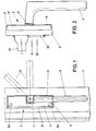
- the handle fitting 2 assigned to a window sash 1 has a rectangular, elongated screw-on plate 3.
- a handle-handling bearing point 4 At the level of the transverse center plane of the screw-on plate 3 there is a handle-handling bearing point 4.
- the latter is designed in the form of a bearing bush which merges into a collar 4 'of larger cross-section at the front.
- a cover plate 5 underpins this collar 4 'and is connected to it in a latching connection, not specified.
- An angled section 5 ′ extends from the cover plate 5, which widens in the direction of the stop surface of the screw-on plate and dips into a corresponding recess 6 of the screw-on plate in a form-fitting manner. In this way, the cover plate 5 is fixed and can only be removed with emphasis.
- the handle handle bearing point extends off-center of the screw-on plate. It supports the pin 7, which continues beyond the collar 4 'into a mandrel 8 with a square cross section. The latter engages positively in the handle 9. If the handle 9 takes the position shown in full lines in FIG. 1, this corresponds to the closed position of the handle fitting. If the handle handle 9 is turned 90 ° counterclockwise, this corresponds to the rotary handle position of the handle fitting. A further rotation of the handle handle counterclockwise leads to a night ventilation position.
- a slide 10 is shifted from position I to positions 11 and III.
- the screw-on plate 3 has a guideway 11 starting from the stop surface, which allows the slide 10 to be displaced in the longitudinal direction of the screw-on plate 3.
- a base 13 extends into the guideway 11 and laterally there are free spaces 14, 15 of different widths.
- Each base 13 contains a threaded bore 16 and a hole 17.
- a countersunk screws 18 which fix a bottom wall B, which bottom wall rests on the bases 13 and closes the guideway 11 except for a through slot 19 for a drive member 10 'which extends perpendicular to the wide surface of the slide 10.
- the through-slot 19 is flanked by a collar 20 which engages in a form-fitting recess in the window sash 1 during assembly and thus pre-centers the handle fitting and additionally stabilizes its position.
- the holes 17 are otherwise aligned with holes 21 in the bottom wall B. Through the holes 17 and holes 21, the screw-on plate fastening screws 50 pass through from the front surface of the screw-on plate 3 and engage in the window sash 1. Then the cover plate 5 is then placed.
- each locking member 23, 24 has a radially directed locking lug 25, for which a receiving opening 26 is provided in the screw-on plate.
- the latter connects the recess 22 to the guideway 11, cf. in particular FIG. 8.
- the locking lug 25 extends approximately in the middle of the locking member 23 or 24.
- An approximately U-shaped spring 27 is used to secure the inserted locking member pivot , whose spring legs 27 'come against flats 28 which are offset by 90 °. In this way, each locking pin pivot can be brought into two locking positions.
- the locking lug 25 In one latching position, the locking lug 25 is located within the receiving opening 26 of the screw-on plate 3. If the locking member pivot 23, 24 is rotated by 90 ° and brought into the other latching position, the lug 25 pivots into the region of the guideway 11.
- a polygonal opening is machined on the end A adjacent the transverse side surface 12, the engagement surfaces 30 trained for a cross-sectional adjustment tool 31.
- each transverse side surface 12 has an insertion opening 29 which is aligned with the engagement surfaces 30.
- the recesses 22 and receiving openings 26 are designed so that they only allow a rotary movement of the locking members 23, 24 by 90 ° with the formation of stop shoulders S 1, S 2 in cooperation with the locking lugs 25.
- the locking lugs 25 of the locking members 23, 24 can optionally form displacement limit stops for the end faces 32, 33 of the slide 10 or they can pivot into locking openings 34 and 35 on the broad side of the slide 10. The latter are designed on one side to bevel 36. Beyond the end faces 32, 33, the slide 10 continues in fork tines 37, 38 which have different cross sections in accordance with the clearances 14, 15. The correct mounting of the slide 10 is therefore always enforced.
- the slide 10 has on its broad side facing the mandrel 8 a groove 39 which extends at an acute angle to its direction of displacement for the entry of a pin 40 which is located on a crank arm 41 which is connected to the mandrel 8 in a rotationally fixed manner. This lies in a semicircular depression V of the screw-on plate 3 starting from the guideway 11.
- the wide surface of the crank arm 41 facing away from the slide engages in a counter detent 42 on the underside of a filler 43 accommodated in a recess 44 of the screw-on plate 3 and also accommodates the mandrel 7, 8 of the handle handle.
- An elastic cushion 45 which extends below the counter-latch 42, acts on the counter-latch 42 in the direction of the crank arm 41.
- a locking channel 46 also extends opposite the locking channel 46.
- the handle fitting can thus be adjusted from right to left or vice versa without changing its structure.
- the cushion 45 could also be omitted.
- the handle 10 can be used to move the slide 10 into the positions from I to the positions according to II and III and back again.
- the pin 40 of the crank arm 41 assumes such a position with respect to the handle-handling bearing position that the push-back forces acting on the slide 10 lead to self-locking.
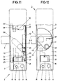
- the slider 10 should only be movable up to the position 11, then as shown in FIGS. 11 and 12, the locking member pivot 24 is to be rotated by 90 °, so that its locking lug 25 plunges into the displacement path of the slider.
- the locking lug thus forms a displacement limit stop for the slide 10.
- FIG. 4 illustrates, the locking lug 25 of the locking member 23 engages in the locking opening 34.
- FIG. 5 The different positions of the pin 40 of the crank arm 41 are illustrated in FIG. 5. There is an approximately sector-shaped one Crank arm 41 before. The pin 41 and the locking grooves 46, 46 'are located on the edge of the crank arm. Otherwise, the mandrel 8 is offset from the longitudinal center plane of the screw-on plate, and the drive member 10 'of the slide 10 is offset in the opposite direction from the longitudinal center of the slide 10.
- the slide 10 is locked in that the one blocking opening 34 'forms a recess 47 for storing a locking plate 48 made of flexible material, which interacts with counter-locking 49 of the bottom wall B.
- the individual switch positions of the handle handle are thus fixed tangibly. In such an embodiment, a detent between the crank arm and filler could then be dispensed with.
Landscapes
- Air-Flow Control Members (AREA)
- Lock And Its Accessories (AREA)
- Catching Or Destruction (AREA)
- Fencing (AREA)
Priority Applications (1)
| Application Number | Priority Date | Filing Date | Title |
|---|---|---|---|
| AT84111109T ATE29162T1 (de) | 1983-11-25 | 1984-09-18 | Griffbeschlag fuer treibstangenbeschlaege von fenstern, tueren oder dergleichen. |
Applications Claiming Priority (2)
| Application Number | Priority Date | Filing Date | Title |
|---|---|---|---|
| DE19838333886U DE8333886U1 (de) | 1983-11-25 | 1983-11-25 | Griffbeschlag fuer treibstangenbeschlaege von fenstern, tueren oder dergleichen |
| DE8333886U | 1983-11-25 |
Publications (3)
| Publication Number | Publication Date |
|---|---|
| EP0143237A1 true EP0143237A1 (fr) | 1985-06-05 |
| EP0143237B1 EP0143237B1 (fr) | 1987-08-26 |
| EP0143237B2 EP0143237B2 (fr) | 1990-02-07 |
Family
ID=6759251
Family Applications (1)
| Application Number | Title | Priority Date | Filing Date |
|---|---|---|---|
| EP84111109A Expired - Lifetime EP0143237B2 (fr) | 1983-11-25 | 1984-09-18 | Ferrure de poignée pour ferrures de tringles coulissantes de fenêtres, portes ou similaires |
Country Status (3)
| Country | Link |
|---|---|
| EP (1) | EP0143237B2 (fr) |
| AT (1) | ATE29162T1 (fr) |
| DE (2) | DE8333886U1 (fr) |
Cited By (1)
| Publication number | Priority date | Publication date | Assignee | Title |
|---|---|---|---|---|
| DE3545859A1 (de) * | 1985-12-23 | 1987-07-02 | Schuermann & Co Heinz | Getriebehandhebel zur betaetigung von fenster- oder tuerbeschlaegen fuer drehbare, kippbare und drehkippbare fluegel |
Citations (7)
| Publication number | Priority date | Publication date | Assignee | Title |
|---|---|---|---|---|
| CH154466A (de) * | 1930-12-11 | 1932-05-15 | Baumann Wilhelm | Verschluss für Tore, Türen, Fensterladen usw. |
| DE958273C (de) * | 1954-06-02 | 1957-02-14 | Richard Waentig | Verdeckt angebrachter Drehstangen-Verschluss fuer Fenster od. dgl. |
| CH382023A (de) | 1959-03-19 | 1964-09-15 | Otto Pelka & Co | Beschlag für Kipp-Schwenk-Flügel von Fenstern, Türen oder dergleichen |
| DE1268013B (de) * | 1964-02-01 | 1968-05-09 | Jaeger Frank K G | Sperreinrichtung in der Befestigungsrosette eines Drehgriffs fuer Betaetigungsgetriebe von in drei Stellungen bewegbaren Treibstangenbeschlaegen fuer Fenster, Tueren od. dgl. |
| AT276145B (de) * | 1966-07-08 | 1969-11-10 | Bilstein August Fa | Einhand-Drehkippbeschlag |
| DE1559967A1 (de) | 1966-12-21 | 1970-03-26 | Eugen Notter Ohg | Schaltgetriebe fuer Drehkippfenster |
| DE2625779A1 (de) * | 1976-06-09 | 1977-12-15 | Eigemeier Willi | Betaetigungsgriff fuer fenster und tueren mit positionssperre |
-
1983
- 1983-11-25 DE DE19838333886U patent/DE8333886U1/de not_active Expired
-
1984
- 1984-09-18 DE DE8484111109T patent/DE3465619D1/de not_active Expired
- 1984-09-18 EP EP84111109A patent/EP0143237B2/fr not_active Expired - Lifetime
- 1984-09-18 AT AT84111109T patent/ATE29162T1/de not_active IP Right Cessation
Patent Citations (7)
| Publication number | Priority date | Publication date | Assignee | Title |
|---|---|---|---|---|
| CH154466A (de) * | 1930-12-11 | 1932-05-15 | Baumann Wilhelm | Verschluss für Tore, Türen, Fensterladen usw. |
| DE958273C (de) * | 1954-06-02 | 1957-02-14 | Richard Waentig | Verdeckt angebrachter Drehstangen-Verschluss fuer Fenster od. dgl. |
| CH382023A (de) | 1959-03-19 | 1964-09-15 | Otto Pelka & Co | Beschlag für Kipp-Schwenk-Flügel von Fenstern, Türen oder dergleichen |
| DE1268013B (de) * | 1964-02-01 | 1968-05-09 | Jaeger Frank K G | Sperreinrichtung in der Befestigungsrosette eines Drehgriffs fuer Betaetigungsgetriebe von in drei Stellungen bewegbaren Treibstangenbeschlaegen fuer Fenster, Tueren od. dgl. |
| AT276145B (de) * | 1966-07-08 | 1969-11-10 | Bilstein August Fa | Einhand-Drehkippbeschlag |
| DE1559967A1 (de) | 1966-12-21 | 1970-03-26 | Eugen Notter Ohg | Schaltgetriebe fuer Drehkippfenster |
| DE2625779A1 (de) * | 1976-06-09 | 1977-12-15 | Eigemeier Willi | Betaetigungsgriff fuer fenster und tueren mit positionssperre |
Cited By (3)
| Publication number | Priority date | Publication date | Assignee | Title |
|---|---|---|---|---|
| DE3545859A1 (de) * | 1985-12-23 | 1987-07-02 | Schuermann & Co Heinz | Getriebehandhebel zur betaetigung von fenster- oder tuerbeschlaegen fuer drehbare, kippbare und drehkippbare fluegel |
| US4790583A (en) * | 1985-12-23 | 1988-12-13 | Schueco Heinz Schuermann Gmbh & Co. | Actuating arrangement for window casement or door leaf fittings |
| EP0226775B1 (fr) * | 1985-12-23 | 1989-07-19 | SCHÜCO International GmbH & Co. | Tige pour l'actionnement du mécanisme d'armatures de fenêtres ou de portes avec vantaux pivotant autour d'axes horizontaux et/ou verticaux |
Also Published As
| Publication number | Publication date |
|---|---|
| EP0143237B1 (fr) | 1987-08-26 |
| ATE29162T1 (de) | 1987-09-15 |
| EP0143237B2 (fr) | 1990-02-07 |
| DE8333886U1 (de) | 1985-04-11 |
| DE3465619D1 (en) | 1987-10-01 |
Similar Documents
| Publication | Publication Date | Title |
|---|---|---|
| EP0283659B2 (fr) | Porte, fenêtre ou similaire dont au moins le battant est construit de profilés en métal ou en matière plastique | |
| EP0226797B1 (fr) | Porte ou fenêtre à tiges de verrouillage commandées par une poignée | |
| EP0440986A2 (fr) | Crémone | |
| DE3645256C2 (de) | Fenster- und Türbeschlag | |
| EP0440987B2 (fr) | Crémone | |
| DE69001664T2 (de) | Profil fuer tuer, fenster oder paneele. | |
| DE3334298C3 (de) | Verschluß für Fenster, Türen oder dergleichen | |
| EP3730730A1 (fr) | Porte levante coulissante ou fenêtre levante coulissante | |
| EP0143237B2 (fr) | Ferrure de poignée pour ferrures de tringles coulissantes de fenêtres, portes ou similaires | |
| EP0128372B1 (fr) | Dispositif de fermeture d'un battant d'une porte, fenêtre ou similaire à deux battants | |
| DE2434120C2 (de) | Drehsicherungsvorrichtung an einem für Fenster, Türen od.dgl. mit wahlweise um zwei Achsen bewegbaren Flügeln, insbesondere Dreh-Kippfenstern, bestimmten Treibstangenbeschlag | |
| EP0672811B1 (fr) | Verrouillage de fausse manoeuvre pour une tringle de commande d'une fenêtre, d'une porte ou similaire | |
| DE69710027T2 (de) | Monodirektionaler Treibstangenverschluss | |
| EP0234213A2 (fr) | Tringle de commande | |
| DE10334933A1 (de) | Kippriegelverschluss für Fenster | |
| DE2524454B2 (de) | Scharnier, für rahmenlose Türen aus Glas | |
| DE2411114C3 (de) | Beschlag für einen aus profilierten Rahmenteilen bestehenden Flügel von Fenstern, Türen od. dgl. | |
| DE3008556C2 (de) | Kippriegel- und Verschlußvorrichtung für Drehkippflügel-Fenster und -Türen oder dgl. | |
| DE10142470C1 (de) | Fehlbedienungssicherung für Treibstangenbeschläge | |
| EP0222067A1 (fr) | Dispositif de verrou de la tringle de commande pour fenêtres, portes ou similaires | |
| DE3320999C1 (de) | Treibstangenbeschlag an einem Fluegelrahmen von Fenstern,Tueren oder dergleichen | |
| DE3240014A1 (de) | Griffanordnung fuer tueren oder dergleichen | |
| DE8609589U1 (de) | Fenster oder Tür mit einem Verriegelungsbeschlag | |
| DE9304389U1 (de) | Verstellbarer Beschlag für Fenster oder Türen | |
| DE29715560U1 (de) | Schwenkhebelverschlußvorrichtung |
Legal Events
| Date | Code | Title | Description |
|---|---|---|---|
| PUAI | Public reference made under article 153(3) epc to a published international application that has entered the european phase |
Free format text: ORIGINAL CODE: 0009012 |
|
| AK | Designated contracting states |
Designated state(s): AT BE CH DE FR GB IT LI LU NL SE |
|
| 17P | Request for examination filed |
Effective date: 19850411 |
|
| 17Q | First examination report despatched |
Effective date: 19860424 |
|
| GRAA | (expected) grant |
Free format text: ORIGINAL CODE: 0009210 |
|
| AK | Designated contracting states |
Kind code of ref document: B1 Designated state(s): AT BE CH DE FR GB IT LI LU NL SE |
|
| REF | Corresponds to: |
Ref document number: 29162 Country of ref document: AT Date of ref document: 19870915 Kind code of ref document: T |
|
| ET | Fr: translation filed | ||
| PG25 | Lapsed in a contracting state [announced via postgrant information from national office to epo] |
Ref country code: LU Free format text: LAPSE BECAUSE OF NON-PAYMENT OF DUE FEES Effective date: 19870930 |
|
| REF | Corresponds to: |
Ref document number: 3465619 Country of ref document: DE Date of ref document: 19871001 |
|
| ITF | It: translation for a ep patent filed | ||
| PLBI | Opposition filed |
Free format text: ORIGINAL CODE: 0009260 |
|
| 26 | Opposition filed |
Opponent name: SIEGENIA-FRANK KG Effective date: 19880502 |
|
| NLR1 | Nl: opposition has been filed with the epo |
Opponent name: SIEGENIA-FRANK KG |
|
| PGFP | Annual fee paid to national office [announced via postgrant information from national office to epo] |
Ref country code: SE Payment date: 19890626 Year of fee payment: 6 Ref country code: FR Payment date: 19890626 Year of fee payment: 6 |
|
| PGFP | Annual fee paid to national office [announced via postgrant information from national office to epo] |
Ref country code: LU Payment date: 19890628 Year of fee payment: 6 |
|
| PGFP | Annual fee paid to national office [announced via postgrant information from national office to epo] |
Ref country code: BE Payment date: 19890710 Year of fee payment: 6 |
|
| PGFP | Annual fee paid to national office [announced via postgrant information from national office to epo] |
Ref country code: AT Payment date: 19890904 Year of fee payment: 6 |
|
| ITTA | It: last paid annual fee | ||
| PGFP | Annual fee paid to national office [announced via postgrant information from national office to epo] |
Ref country code: NL Payment date: 19890930 Year of fee payment: 6 |
|
| PGFP | Annual fee paid to national office [announced via postgrant information from national office to epo] |
Ref country code: CH Payment date: 19891108 Year of fee payment: 6 |
|
| PUAH | Patent maintained in amended form |
Free format text: ORIGINAL CODE: 0009272 |
|
| STAA | Information on the status of an ep patent application or granted ep patent |
Free format text: STATUS: PATENT MAINTAINED AS AMENDED |
|
| 27A | Patent maintained in amended form |
Effective date: 19900207 |
|
| AK | Designated contracting states |
Kind code of ref document: B2 Designated state(s): AT BE CH DE FR GB IT LI LU NL SE |
|
| NLR2 | Nl: decision of opposition | ||
| ET3 | Fr: translation filed ** decision concerning opposition | ||
| NLR3 | Nl: receipt of modified translations in the netherlands language after an opposition procedure | ||
| ITF | It: translation for a ep patent filed | ||
| PG25 | Lapsed in a contracting state [announced via postgrant information from national office to epo] |
Ref country code: AT Effective date: 19900918 |
|
| PG25 | Lapsed in a contracting state [announced via postgrant information from national office to epo] |
Ref country code: SE Effective date: 19900919 |
|
| PG25 | Lapsed in a contracting state [announced via postgrant information from national office to epo] |
Ref country code: LI Effective date: 19900930 Ref country code: CH Effective date: 19900930 Ref country code: BE Effective date: 19900930 |
|
| BERE | Be: lapsed |
Owner name: CARL FUHR G.M.B.H. & CO. Effective date: 19900930 |
|
| PG25 | Lapsed in a contracting state [announced via postgrant information from national office to epo] |
Ref country code: NL Effective date: 19910401 |
|
| NLV4 | Nl: lapsed or anulled due to non-payment of the annual fee | ||
| PG25 | Lapsed in a contracting state [announced via postgrant information from national office to epo] |
Ref country code: FR Effective date: 19910530 |
|
| REG | Reference to a national code |
Ref country code: CH Ref legal event code: PL |
|
| REG | Reference to a national code |
Ref country code: FR Ref legal event code: ST |
|
| PGFP | Annual fee paid to national office [announced via postgrant information from national office to epo] |
Ref country code: GB Payment date: 19910806 Year of fee payment: 8 |
|
| PGFP | Annual fee paid to national office [announced via postgrant information from national office to epo] |
Ref country code: DE Payment date: 19910905 Year of fee payment: 8 |
|
| PG25 | Lapsed in a contracting state [announced via postgrant information from national office to epo] |
Ref country code: GB Effective date: 19920918 |
|
| GBPC | Gb: european patent ceased through non-payment of renewal fee |
Effective date: 19920918 |
|
| PG25 | Lapsed in a contracting state [announced via postgrant information from national office to epo] |
Ref country code: DE Effective date: 19930602 |
|
| EUG | Se: european patent has lapsed |
Ref document number: 84111109.9 Effective date: 19910527 |