EP0143331A1 - Circuit pour mesure de la vitesse de rotation de l'armature à encoches d'une machine à champ tournant - Google Patents
Circuit pour mesure de la vitesse de rotation de l'armature à encoches d'une machine à champ tournant Download PDFInfo
- Publication number
- EP0143331A1 EP0143331A1 EP84112838A EP84112838A EP0143331A1 EP 0143331 A1 EP0143331 A1 EP 0143331A1 EP 84112838 A EP84112838 A EP 84112838A EP 84112838 A EP84112838 A EP 84112838A EP 0143331 A1 EP0143331 A1 EP 0143331A1
- Authority
- EP
- European Patent Office
- Prior art keywords
- frequency
- circuit arrangement
- signal
- arrangement according
- armature
- Prior art date
- Legal status (The legal status is an assumption and is not a legal conclusion. Google has not performed a legal analysis and makes no representation as to the accuracy of the status listed.)
- Granted
Links
Images



Classifications
-
- G—PHYSICS
- G01—MEASURING; TESTING
- G01P—MEASURING LINEAR OR ANGULAR SPEED, ACCELERATION, DECELERATION, OR SHOCK; INDICATING PRESENCE, ABSENCE, OR DIRECTION, OF MOVEMENT
- G01P3/00—Measuring linear or angular speed; Measuring differences of linear or angular speeds
- G01P3/42—Devices characterised by the use of electric or magnetic means
- G01P3/44—Devices characterised by the use of electric or magnetic means for measuring angular speed
- G01P3/48—Devices characterised by the use of electric or magnetic means for measuring angular speed by measuring frequency of generated current or voltage
Definitions
- the invention is based on a method for measuring the speed of a grooved armature of a induction machine with at least two stator windings, at least one of which is traversed by a current, the number of armature slots not being an integral multiple of the number of poles of the stator, and the basic frequency of the excitation current for the stator windings is suppressed.
- the invention relates to a circuit arrangement for measuring the speed of a slotted armature of an induction machine, wherein at least g a stator winding of a Erre erstrom flows through and is supported by the rotating armature generated in the stator winding, a frequency signal, coupled with an electrically to at least one of the stator windings Device for suppressing the fundamental frequency of the current fed into the stator winding, the number of armature slots not being an integral multiple of the number of stator poles.
- a current transformer is connected in one of the three current leads for the three-phase asynchronous motor, the output of which is connected to the input of a bandpass.
- the cut-off frequencies of the bandpass coincide with an overtone of the fundamental frequency of the motor current, the order of the overt tones is ten or eleven, while the attenuation of the bandpass is outside the pass band at about 60 dB.
- the frequency mixture obtained at the output of the bandpass passes into an envelope detector, where it is correspondingly envelope-demodulated, taking advantage of the effect that the frequency of the envelope signal is related to the slip in a predeterminable manner.
- the amplitude of the slip frequency signal also depends strongly on the slip of the asynchronous motor and approaches zero when the slip disappears.
- the known method determines the speed of the asynchronous motor via the slip, it can only be used in load areas of the motor where there is considerable slip, because otherwise, as stated above, the amplitude of the frequency signal tends to zero very quickly, and on top of that the slip frequency goes to zero. With synchronism, the slip frequency is zero.
- the known method is also not suitable for speed measurement in braking operation, in which there are very complicated relationships between the armature speed and the slip frequency, which is why the output signal of the envelope detector can no longer be used for speed measurement.
- the object of the invention is, therefore, the initially mentioned method and the aforementioned formwork tungsanordnun so further develop g, that the rotational speed of the armature of a rotary electric machine without determination of slip substantially directly from the signal voltages and currents of the stator windings can be measured.
- the method according to the invention is characterized in that the fundamental frequency of the frequency signal caused by the anchor grooves is used as a parameter for the speed, while the circuit arrangement is characterized in that it processes the fundamental frequency of the frequency signal caused by the anchor grooves and on it Output emits a signal whose frequency is proportional to the armature speed.
- the main advantage here is that a frequency signal with a relatively large amplitude and a relatively high frequency is evaluated in the normal load case of the induction machine, which is therefore easy to use. Only at very low armature speeds does the frequency of the evaluated frequency signal reach the order of magnitude of the basic frequency of the excitation current for the induction machine, which results in an overall speed range that extends from the synchronous speed to almost standstill. In this way, the speed can also be easily monitored with three-phase machines braked with direct current.
- the frequency signal can be tapped from a winding as a voltage signal. If the induction machine is operated in braking mode, a winding free of the excitation current is expediently used for this purpose, because the interference signal as a result of the DC braking current is not superimposed on the useful signal.
- the frequency signal is tapped as a voltage signal on two windings connected at one end
- the alternating voltage components compensate each other in the event of braking, in which phase-cut half-wave rectified alternating current is generally used, so that the signal tapped at the two free ends of the winding practically only compensates for the Contains useful signal component and an additional filter circuit is unnecessary.
- the method for determining the rotational speed can be both used if the excitation current is used for braking the armature and having a Gleichkom p onen- te or when the rotary field machine in motor mode operates and the excitation current includes only AC component, which is readily he It is evident that a number of the above circuits are not limited to three-phase asynchronous machines, but can also be used, for example, in capacitor motors.
- An easy way to separate the frequency signal is to use a filter that is connected to the stator windings or the current transformer. It has turned out to be advantageous if the filter is selected with a slope of approximately 36 dB per octave, because this represents a favorable compromise between settling time and signal separation.
- the cut-off frequency of the filter designed as a high-pass filter is approximately three times the basic frequency of the excitation current because the useful signal is above the mains frequency within the speed range of interest.
- phase shifter network contains at least two inputs, which are either connected in parallel to corresponding stator windings or into which voltages tapped at current transformers are fed, wherein the current transformers are located in the power supply lines of two phase windings.
- the tapped voltages are superimposed on one another with a phase rotated by 180 °, so that only the frequency components of the excitation current or its harmonics are suppressed.
- the circuit arrangement for speed measurement is occidentalromes contains in one embodiment a high pass filter whose cutoff frequency g on the fundamental frequency of the AC component of the Erre.
- the cut-off frequency is advantageously about three times the basic frequency of the alternating component of the excitation current, because this also suppresses the first odd harmonic of the excitation current, which is caused by the non-linear magnetization curve of iron and, depending on the iron utilization, can have a relatively large amplitude, which may interfere with an evaluation circuit downstream of the circuit arrangement, for example a frequency counter, as a tachometer.
- the filter has a slope of 36 dB per octave at frequencies below the cut-off frequency.
- This high Pass filter can easily be made as an active filter with a Butterworth characteristic.
- the circuit arrangement with high-pass filter for separating the frequency signal at the input of the highpass filter is parallel to one of the stator windings or, if the stator winding to a V oltage source with a very low internal resistance, such as the normal mains supply is connected, it is advantageous if the circuit arrangement contains a current transformer, the output of which is at the input of the high-pass filter, while the current transformer itself is switched on in one of the power supply lines to one of the stator windings.
- the circuit arrangement contains a network with two parallel signal paths, each having an input, which are connected on the output side to a logic circuit with an output in the network.
- each of these two signal paths is either parallel to an associated stator winding or parallel to the output of an associated current transformer, which in another exemplary embodiment also belongs to the network.
- the current transformers of the network are connected in the power supply lines to the stator windings and generate a current-proportional signal at their output, which is fed into the signal paths.
- At least one of the signal paths contains a frequency-independent damping device which is dimensioned such that the outputs Voltage of the logic circuit is minimized when the two of the interference signal are rotated 180 0 in phase in the two inputs fed signal voltages with respect to what is met, for example during the braking operation of the motor without difficulty.
- one of the two signal paths of the network contains a phase shifter, which is in turn adjusted so that the output voltage of the logic circuit is minimal, ie is set to that the phases of the undesirable Kirkom p onents at the two inputs of the network are rotated 180 against each other, so that they cancel each other out at the logic circuit.
- phase shifter can be provided in each of the two signal paths, one of which rotates forwards and the other reverses, so that the desired 180 ° phase rotation is achieved overall.
- the phase shifter itself which in the simplest case consists of a capacitor and a resistor, can be designed as a voltage divider in order to save components.
- one signal path as a frequency-independent damping device contains an ohmic series resistor and the other signal path as a phase shifter contains a capacitive Länas resistor, while the linking circuit consists of an ohmic transverse resistor, because in this way the amplitudes and the Phase adjustment can be made. If no Phasenan p assung necessary, the series resistors can also be carried out in each case in the two signal paths as ohmic series resistors.
- the circuit arrangement can be further simplified in that a network connected on the input side to the three phases is used to generate an artificial star point, between the artificial star point, which can also be the center of the network, and the star point of the asynchronous motor, the speed-proportional output signal is tapped.
- the circuit arrangement has a switching stage for separating signal components caused by the excitation current, the amplitude of which is smaller than the amplitude of the fundamental frequency of the frequency signal caused by the armature grooves, the frequency of the output signal the switching stage of the armature speed is proportional.
- this switching stage consists of a flip-flop with a switching hysteresis, for example a Schmitt trigger or a single-stage counter, the two switching thresholds of which are at a corresponding distance from one another.
- This switching stage is connected on the input side to the output of the filter or the phase shifter network ".
- the switching stage can also be connected directly between the points mentioned on the input side.
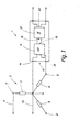
- the three-phase machine 2 shown is a 3-phase asynchronous motor with a grooved ferromagnetic armature and three strands 3, 4 and 5, which - as illustrated - are connected in a star, i.e. they are at one end at a star point 6, while their other connections 7, 8 and 9 are not connected to one another.
- a direct current is fed into line 3 via lines 11, 12, with which the armature of the induction machine 2 is to be braked.
- the direct current supplied via lines 11 and 12 comes from a DC voltage source which is not known per se and is generated, for example, by half-wave rectification from the mains voltage for operating the induction machine 2.
- the circuit arrangement 1 has two input terminals 14 and 15 forming its input 13, with which it is connected via corresponding connecting lines to the star point 6 and the strand end 9 of the strand 5, ie the input 13 of the circuit arrangement 1 is connected in parallel to the strand 5.
- the circuit arrangement 1 itself contains a high-pass filter 16, which is connected with its input 17 in parallel to the terminals 14 and 15.
- An output 18 of the high-pass filter 16 is connected to an input 19 of a switching stage 21, the output 22, at the same time forms the output of the circuit arrangement 1.
- the armature of the induction machine 1 which rotates at the rated speed at the beginning of the braking process, causes an additional modulation of the the strand 3 generated magnetic field, due to its groove, which causes a corresponding change in the magnetic resistance in the magnetic circuit of the induction machine 2 and thus also a periodic change in the magnetic flux in the strand 5.
- this speed-dependent frequency signal contains further harmonics which are in whole-number relation to the fundamental frequency caused by the armature grooves.
- the speed of the armature is obtained from that through the armature grooves caused frequency signal, wherein only the fundamental frequency is evaluated, since its amplitude is much larger than that of the associated harmonic.
- the speed therefore results in:
- the fundamental frequency of the frequency signal caused by the armature grooves is proportional to the speed of the armature via the proportionality factor 60 / Z, and it can easily be used as a parameter for the motor speed.
- This high-pass filter is a sixth-order Butterworth filter with a slope of 36 dB / linguistic linguistics, the limit frequency of the high-pass filter 16 depending on the expected amplitude ratio between the second or third harmonic due to the unsmoothed direct current in phase 3 and the amplitude of the fundamental frequency of the frequency signal, which is generated by the armature grooves, either slightly above twice or slightly over three times the value of the fundamental frequency of the current flowing through the strand 3.
- the cut-off frequency of the high-pass filter 16 is equal to or slightly greater than three times the value of the fundamental frequency of the current in phase 3, ie at one half-wave rectified alternating current of 50 Hz, the cut-off frequency of the high-pass filter 16 is 150 Hz.
- a frequency signal is thus obtained which is freed of low-frequency interference signals. Since the higher-frequency interference signals all have a smaller amplitude than the fundamental frequency of the frequency signal caused by the armature grooves, they are no longer disruptive and do not need to be further filtered out.
- the signal coming from the high-pass filter 16 reaches the input 19 of the switching stage-21, which has a switching characteristic like a Schmitt trigger, but has a low switching hysteresis.
- the switching stage 21 serves to convert the signal coming from the high-pass filter 16 into a square-wave signal of the same frequency but with a constant amplitude.
- the amplitude of the signal from the high-pass filter 16 initially changes at least with the speed of the armature of the induction machine 2, ie, as the speed decreases, the amplitude of the fundamental frequency of the frequency signal caused by the armature grooves also decreases.
- the amplitude of the frequency signal is also dependent on the size of the current through the strand 3 insofar as the amplitude of the desired frequency signal also decreases with decreasing excitation current in the strand 3.
- an additional amplitude modulation is superimposed on the frequency signal caused by the armature grooves, which accordingly also appears at the output 18 of the high-pass filter 16 and may be disruptive.
- the downstream switching stage 21 With the help of the downstream switching stage 21, the amplitude fluctuations occurring for the reasons mentioned above are eliminated, so that a square-wave signal can be tapped off at the output 22 of the switching stage 21, the frequency of which corresponds to the fundamental frequency of the frequency signal caused by the armature grooves.
- This signal obtained in this way in which the frequency of the armature speed of the induction machine 2 is directly proportional, can now be used in a known manner, for example for immediate speed display, in that the output 22 of the switching stage 21, i.e. a digital frequency counter is connected to the output of the circuit arrangement 1, which is tuned in such a way that it takes into account the proportionality factor and immediately indicates the speed of the armature of the induction machine 2.
- the output 22 of the switching stage 21, i.e. a digital frequency counter is connected to the output of the circuit arrangement 1, which is tuned in such a way that it takes into account the proportionality factor and immediately indicates the speed of the armature of the induction machine 2.
- the frequency signal used for the speed measurement which is caused by the armature grooves, as a voltage variable on a strand free of the braking current, namely, as shown, strand 5.
- a current transformer belonging to the circuit arrangement 1 in the current supply line to the line 3 the secondary side of which is located at the input 17 of the high-pass filter 16, since the frequency signal to be evaluated is also superimposed on the current flowing through the line 3.
- This frequency signal always occurs when the number of armature slots is not an integral multiple of the number of poles of the induction machine 2.
- FIG. 2 illustrates a further application example of the circuit arrangement 1 according to FIG. 1, which is now used to measure the speed of the armature of the induction machine 2, which, however, operates here in motor operation, which is why its strands 3, 4 and 3 are connected in a star 5 are connected with their free ends 7, 8 and 9 to the three phases R, S and T of a three-phase network.
- the circuit arrangement 1 is again constructed in exactly the same way as the circuit arrangement 1 according to FIG. 1 and therefore is no longer explained in detail.
- the circuit arrangement 1 is connected when the induction machine 2, which is connected to a star, is operating in motor mode, again in such a way that the input 13 of the circuit arrangement 1 is connected in parallel to one of the strands 3, 4 or 5.
- the mode of operation is as above described, ie at the output 22 is at a square wave signal whose frequency is equal to the fundamental frequency of the g of the armature slots out e-called frequency signal, and thus the speed of the armature of the induction machine 2, as described, is directly proportional.
- the star point 6 is otherwise not connected to the network but is connected in a triangle, or if the star point 6 is connected to the center of the network,
- the circuit arrangement 1 can be expanded by a current transformer, the secondary side of which is connected to the input 17 of the high-pass filter 16 and the primary side of which is in one of the current supply lines of the R, S or T phases.
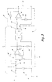
- circuit arrangement 1 which is illustrated as a block diagram in FIGS. 1 and 2, is now explained in detail with reference to FIG. 3.
- the filter stage 25 contains two capacitors 28 and 29 connected in series, which connect the common connection point from the two resistors 23 and 24 to the non-inverting input 31 of a differential amplifier 32.
- a resistor 33 leads from the non-inverting input 31 to the input terminal 15, which further represents the circuit ground in the circuit shown.
- the output 34 of the differential amplifier 32 is also connected to the circuit ground via the series circuit comprising two resistors 35 and 36, i.e. the input terminal 15, while the connection point between the two resistors 35 and 36 is connected to the inverting input 37 of the differential amplifier 32, whereby a predetermined negative feedback is achieved.
- a further resistor 38 leads from the output 34 of the differential amplifier 32 to the junction of the two capacitors 28 and 29 connected in series, which brings about a corresponding positive feedback in a predetermined frequency range.
- the output 34 of the differential amplifier 32 simultaneously forms the output of the filter stage 25 to which the filter stage 26 is connected, specifically with a capacitor corresponding to the capacitor 28, since the filter stage is constructed identically to the filter stage 25.
- a three-stage high-pass filter 16 is formed in this way, which contains at its input a voltage divider from the resistors 23 and 24, with which the voltage between the input terminals 14 and 15 to one processable value for the subsequent filter stages 24, 26 and 27 is divided down, which is necessary because the frequency signal caused by the armature grooves, as described above, is superimposed on further AC voltage signals with a substantially greater amplitude.
- the switching stage 21 To the output 18 of the high-pass filter 16, which is formed by the output of the filter stage 27, the switching stage 21 is connected, which contains as an active element a differential amplifier 39, the output 41 of which, together with the circuit ground, given by the input terminal 15, the output 22 the circuit arrangement 1 forms.
- a positive feedback resistor 42 leads from the output 41 of the differential amplifier 39 to the non-inverting input of the differential amplifier 39, which is connected to the output of the differential amplifier in the filter stage 27 via a further series resistor 43.
- a resistor 44 leads from the inverting input of the differential amplifier 39 to the circuit ground.
- the high-pass filter 16 is used in the exemplary embodiment of the circuit arrangement 1 according to FIGS. 1 to 3 for suppressing the undesired frequency signals due to the harmonics on the DC braking current or the motor current in the case of motor operation
- the circuit arrangement shown in FIGS the unwanted frequency signals and separating the frequency signal caused by the armature grooves with which the engine speed is to be measured, a compensation network 51.
- the induction machine 2 is constructed, as previously explained, which is why the same reference numerals are used here. The components of the induction machine 2 identified therewith are not described again.
- the Com p ensationsnetztechnik 51 includes two parallel signal paths 52 and 53 with two input terminals 54, 55 and 56, 57 and two output terminals 58, 59 and 61 and 62.
- the two input terminals 54, 55 and 56, and 57 of the two Si g nal p fade 52 and 53 form their input, which, as shown in Fig. 4, is connected in parallel to a respective associated string, ie the signal path 52 is with its input terminals 54 and 55 at the star point 6 and the string connection 7 of Line 3, whereas the signal path 53 is coupled with its input terminal 57 to the star point 6 and with its input terminal 56 to the line connection 8 of the line 4.
- the signals coming from the two signal paths 52 and 53 reach a logic circuit 63 with a total of three input connections 64, 65 and 66 and two output connections 67 and 68.
- the output terminal 58 of the signal path 52 is connected to the input terminal 64 and the output terminal 61 of the signal path 53 is connected to the input terminal 65, while the two output terminals 59 and 62 are connected together to the input terminal 66 .
- the two output terminals 67 and 68 of the logic circuit 63 which serves to superimpose the two signals from the signal paths 52 and 53, form the output of the network 51, which in this respect corresponds to the output 18 of the filter 16 and is therefore also designated 18 is.
- the output 18 of the network 51 is connected to the input 19 of the subsequent switching stage 21, which can be constructed as previously described.
- the two frequency signals come from the two signal paths 52 and 53 to the logic circuit 63, in which they are superimposed on one another, as a result of which all signal components which have the same amplitude and the same frequency but the opposite phase position are extinguished at this point.
- Signal components with different frequencies, different amplitudes or phase positions deviating from 180 ° pass through the logic circuit 63 more or less weakened.
- the frequency signals caused by the armature grooves in the two lines 3 and 4 have a phase position that is different from each other by 180 °, so that they do not cancel each other out in the logic circuit 63, but rather pass through the logic circuit 63 essentially without weakening.
- a frequency signal is thus available which essentially only contains the frequency signal caused by the anchor grooves, the fundamental frequency of which has the greatest amplitude and thus exclusively controls the subsequent switching stage 21 with Schmitt trigger characteristics.
- a square-wave signal is therefore available at the output 22 of the switching stage 21 and thus at the output of the circuit arrangement 50, the frequency of which is equal to the fundamental frequency of the frequency signal caused by the armature grooves and the amplitude of which is constant. It can be prevented by appropriate selection of the hysteresis of the switching stage 21 that any higher-frequency disturbances with a small amplitude disturb the output signal of the switching stage 21.
- the circuit arrangement 50 with the network 51 has particular advantages if the braking direct current for the induction machine 2 is set with the aid of a phase gating control, because at the same time it effectively eliminates amplitude modulations which occur in phases 3 and 4 due to the phase gating, which is otherwise because the possible shift of the DC voltage zero to a frequency modulation at the output of the circuit arrangement 50 could lead to the generation of a speed-proportional frequency signal.
- Fig. 4 also shows that the circuit arrangement 50 can also be used when the string 5 is not connected as shown, but is connected between the string connections 7 and 8, so that the induction machine 2 is connected in a triangle as a whole. Furthermore, from Fi g. 4 also show that the induction machine 2 need not be a three-phase asynchronous motor, but can also be a capacitor motor to which the circuit arrangement 50 is connected, as shown.
- the circuit configuration of the network 51 which is shown in Fig. 4 only as a block diagram, Fig. 5. Thereafter, contains the signal path 52 as a frequency-independent damping means between its two terminals 54 and 58 a County g swiderstand 71, while the two terminals 55 and 59 are directly wired through.
- the logic circuit 63 consists of only one shunt resistor 73, which is connected at one end to the input terminal 66 and at the other end to the two input terminals 64 and 65.
- the voltages induced by the DC braking current only differ in amplitude, this can be compensated for by appropriate selection of the series resistances 71 and 72 are so that the voltages tapped on the strands can be brought to the same amplitude with respect to the signal to be suppressed by the choice of the values of the series resistors 71 and 72.
- the two series resistors 71 and 72 only serve to decouple the inputs 54 and 56 of the two signal paths 52 and 53 from one another in such a way that no short circuit between the line connections 7 and 8 occurs through the logic circuit 63.
- the induction machine 2 does not operate in braking mode, but in motor operation, in which the voltages on the strands of a three-phase induction machine 2 connected in a star are phase-shifted from one another by 120 °, it is necessary to at least in one of the two signal paths 52 or 53 to provide a phase shifter, for example in signal paths 53, as shown in FIG. 6. If the phase shifter, in the case of the signal path 53, introduces additional attenuation, a corresponding attenuation in the other signal path, i.e. can be provided in the signal path 52.
- the frequency signal with the greatest amplitude is thus canceled out in the logic circuit 63, in which the output voltages of the two signal paths 52 and 53 are superimposed on one another, as described above. It is particularly advantageous if an all-pass is used in the signal path 53 as a phase shifter, which ensures that the third harmonic of the mains fundamental frequency, which is generated by the nonlinear magnetization curve of the induction machine 2, is rotated in such a way that it also rotates during the Overlaps with the signal from signal path 52. In the vast majority of cases, however, it is sufficient if the above-mentioned phase condition is established only for the fundamental frequency of the supplying AC mains voltage, because its amplitude is more than an order of magnitude above the amplitudes of the other frequency signals.
- FIG. 7 shows the circuit diagram for such an application, the signal path 52, as in FIG. 5, only containing the length resistor 71 as a damping device, which together with the input resistance of the logic circuit 63 forms a voltage divider, while the signal path 53 instead of the series resistor 72 contains a phase-shifting capacitor 74 which, together with the transverse resistor 73 of the logic circuit 63, forms a high-pass filter.
- the induction machine to be monitored has 2 symmetrical windings
- the following dimensioning rule applies to the passive components of the network 51: and where R L is the value of resistor 71, C is the capacitance of capacitor 74, R Q is the value of resistor 73 and w is the angular frequency of the AC supply voltage.
- the quotient of Q R and ⁇ C must be selected for a three-p hasiges three-phase system so as to give ⁇ at the mains frequency to 60 °.
- the frequency signals which are generated by the AC mains voltages on the two strands 3 and 5, are rotated by 180 ° with respect to one another and are canceled in the logic circuit 63, namely the transverse resistor 73, while all the others Signals pass the logic circuit 63 more or less weakened. Since the frequency signal, which is caused by the armature slots, has a greater amplitude than the third harmonic of the mains frequency, the subsequent switching stage 21 is followed by an appropriate choice of the switching points, that corresponds s p raking choice of switching hysteresis, only the frequency signal obtained by the Armature grooves is generated so that the output signal at switching stage 21 is in turn proportional to the speed of the armature.
- the frequency signal caused by the armature groove must be decoupled via current transformers, which are connected on the primary side in two power lines to the induction machine 2, as shown in FIG. 8.
- the circuit arrangement 50 for generating the speed-proportional signal therefore contains, in contrast to the exemplary embodiment according to FIGS. 6 and 7, two current transformers 77 and 78, each with galvanically separated primary and secondary sides 79, 81 or 82 and 83.
- the primary side 79 of the Current transformer 77 lies between phase R of the three-phase network and the associated connection 7 of induction machine 2, while primary side 82 of current transformer 78 is switched on between phase T and connection 9.
- the secondary side 81 of the current transformer 21 is connected to the input terminals 54 and 55 of the signal path 52, while the secondary side 83 of the current transformer 78 is connected to the input terminals 56 and 57 of the signal path 53.
- a voltage proportional to the phase currents is fed to the two signal paths 52 and 53, which are otherwise constructed as previously described, and in addition to the frequency signal resulting from the AC line voltage or its harmonic waves, the frequency signal contains, which is caused by the anchor grooves.
- the dimensioning of the network 51 suppresses the frequency signal with the frequency of the AC mains voltage, so that essentially only the frequency signal caused by the anchor grooves is present at the output 18 of the network 51, the immediate bar is proportional to the armature speed and controls the subsequent switching stage 21.
- the frequency signal proportional to the speed of a three-phase induction machine 2 connected in a star can also be generated in that the star point 6, which is not connected to the center of the network, is connected to one of the input terminals 19a of the switching stage 21 with Schmitt trigger characteristic, while the other Input 19b is located at the junction of three resistors 85, 86 and 87, each of the resistors 85 to 87 being connected to an associated phase R, S or T of the three-phase three-phase network.
- the input 19b of the switching stage 21 forms an artificial star point as a reference point compared to the frequency signal generated by the armature slots at the star point 6 of the induction machine 2 as an alternating voltage, which is fed to the switching stage 21 via the input 19a.
- the switching stage 21 converts the fed-in frequency signal into a square-wave signal of the same frequency and constant amplitude, so that the frequency signal proportional to the armature speed can in turn be tapped for further use at the output 22 of the switching stage 21.
- the resistors 85 to 87 can be omitted and instead the input inclusion 19b of the switching stage 21 can be connected directly to the center point M, as is the case with this is drawn in dashed lines in FIG. 9.
- Filters with a compensation circuit for at least the basic frequency of the excitation current which is shown in FIGS. 4 to 9, enable the generation of the frequency signal proportional to the number of waves from the basic frequency of the frequency signal caused by the armature grooves up to almost the standstill of the armature, i.e. in the range of the frequency of the Erreaer current.
- a high-pass filter can also be interposed between the output 18 of the network 51 and the input 19 of the switching stage 21, with which frequency signals which cannot be suppressed by the network 51 are filtered out in order to disrupt the To prevent operation of the subsequent switching stage 21.
- the cut-off frequency of such a high-pass filter is set to the lower frequency limit of the frequency range to be evaluated for the frequency signal caused by the armature grooves, or the cut-off frequency can also be set at the fundamental frequency of the excitation current or to the second or third harmonic of the fundamental frequency of the excitation current be.
- the high-pass filter 16 described with reference to FIG. 3 can be used as the high-pass filter. In the large number of cases, however, a very steep-sided high pass will not be necessary, but a simple RC high pass, the dimensions of which are known to the person skilled in the art, will suffice.
Landscapes
- Physics & Mathematics (AREA)
- General Physics & Mathematics (AREA)
- Control Of Ac Motors In General (AREA)
- Synchronous Machinery (AREA)
- Dc Machiner (AREA)
- Tests Of Circuit Breakers, Generators, And Electric Motors (AREA)
Priority Applications (1)
| Application Number | Priority Date | Filing Date | Title |
|---|---|---|---|
| AT84112838T ATE45631T1 (de) | 1983-10-29 | 1984-10-25 | Schaltungsanordnung zum messen der drehzahl eines genuteten ankers einer drehfeldmaschine. |
Applications Claiming Priority (2)
| Application Number | Priority Date | Filing Date | Title |
|---|---|---|---|
| DE3339299 | 1983-10-29 | ||
| DE3339299A DE3339299C2 (de) | 1983-10-29 | 1983-10-29 | Schaltungsanordnung zum Messen der Drehzahl eines genuteten Ankers einer Drehfeldmaschine |
Publications (2)
| Publication Number | Publication Date |
|---|---|
| EP0143331A1 true EP0143331A1 (fr) | 1985-06-05 |
| EP0143331B1 EP0143331B1 (fr) | 1989-08-16 |
Family
ID=6213040
Family Applications (1)
| Application Number | Title | Priority Date | Filing Date |
|---|---|---|---|
| EP84112838A Expired EP0143331B1 (fr) | 1983-10-29 | 1984-10-25 | Circuit pour mesure de la vitesse de rotation de l'armature à encoches d'une machine à champ tournant |
Country Status (3)
| Country | Link |
|---|---|
| EP (1) | EP0143331B1 (fr) |
| AT (1) | ATE45631T1 (fr) |
| DE (2) | DE3339299C2 (fr) |
Cited By (3)
| Publication number | Priority date | Publication date | Assignee | Title |
|---|---|---|---|---|
| EP0287852A3 (fr) * | 1987-04-09 | 1989-02-01 | Siemens Aktiengesellschaft | Procédé et appareil pour mesurer la vitesse de rotation d'une machine électrique |
| US4839589A (en) * | 1985-12-12 | 1989-06-13 | Siemens Aktiengesellschaft | Method and circuit for determining the speed of rotation of a rotating machine |
| CN114252766A (zh) * | 2020-09-22 | 2022-03-29 | 南京磁之汇电机有限公司 | 传感器及转角转速信号提取方法 |
Families Citing this family (6)
| Publication number | Priority date | Publication date | Assignee | Title |
|---|---|---|---|---|
| DE3536227A1 (de) * | 1985-08-19 | 1987-02-26 | Siemens Ag | Verfahren und vorrichtung zur drehzahlmessung an einer drehfeldmaschine |
| DE3606741A1 (de) * | 1986-03-01 | 1987-09-03 | Pilz Gmbh & Co | Selbsttaetig arbeitende stern-dreieck-umschalteinrichtung |
| DE3824811A1 (de) * | 1988-07-21 | 1990-01-25 | Teves Gmbh Co Ohg Alfred | Verfahren zur messung der anzahl von umdrehungen eines gleichstrommotors |
| DE4108522C2 (de) * | 1991-03-15 | 1994-03-17 | Grundfos International A S Bje | Vorrichtung zur Drehzahlmessung |
| DE4322146A1 (de) * | 1993-07-02 | 1995-01-19 | Hueller Hille Gmbh | Verwendung eines elektrischen Antriebes für Bearbeitungsspindeln und Vorschubachsen an Werkzeugmaschinen |
| DE102004042664A1 (de) | 2004-09-01 | 2006-03-02 | Wilo Ag | Verfahren zur berührungslosen Drehzahlmessung für Elektromotoren |
Citations (5)
| Publication number | Priority date | Publication date | Assignee | Title |
|---|---|---|---|---|
| US3439245A (en) * | 1967-02-28 | 1969-04-15 | Gen Electric | Rotor speed sensing circuit |
| FR2095378A1 (fr) * | 1970-06-20 | 1972-02-11 | Bodenseewerk Geraetetech | |
| DE2355787A1 (de) * | 1973-11-08 | 1975-06-12 | Licentia Gmbh | Verfahren zur erfassung der drehzahl eines elektromotors |
| FR2479474A1 (fr) * | 1980-03-26 | 1981-10-02 | Elfi Innovationer | Procede et appareillage pour detecter la vitesse d'un moteur asynchrone |
| FR2507782A1 (fr) * | 1981-06-16 | 1982-12-17 | Valeo | Tachymetre pour un dispositif electrique a commutation, en particulier pour un moteur electrique |
-
1983
- 1983-10-29 DE DE3339299A patent/DE3339299C2/de not_active Expired
-
1984
- 1984-10-25 AT AT84112838T patent/ATE45631T1/de not_active IP Right Cessation
- 1984-10-25 DE DE8484112838T patent/DE3479444D1/de not_active Expired
- 1984-10-25 EP EP84112838A patent/EP0143331B1/fr not_active Expired
Patent Citations (5)
| Publication number | Priority date | Publication date | Assignee | Title |
|---|---|---|---|---|
| US3439245A (en) * | 1967-02-28 | 1969-04-15 | Gen Electric | Rotor speed sensing circuit |
| FR2095378A1 (fr) * | 1970-06-20 | 1972-02-11 | Bodenseewerk Geraetetech | |
| DE2355787A1 (de) * | 1973-11-08 | 1975-06-12 | Licentia Gmbh | Verfahren zur erfassung der drehzahl eines elektromotors |
| FR2479474A1 (fr) * | 1980-03-26 | 1981-10-02 | Elfi Innovationer | Procede et appareillage pour detecter la vitesse d'un moteur asynchrone |
| FR2507782A1 (fr) * | 1981-06-16 | 1982-12-17 | Valeo | Tachymetre pour un dispositif electrique a commutation, en particulier pour un moteur electrique |
Cited By (3)
| Publication number | Priority date | Publication date | Assignee | Title |
|---|---|---|---|---|
| US4839589A (en) * | 1985-12-12 | 1989-06-13 | Siemens Aktiengesellschaft | Method and circuit for determining the speed of rotation of a rotating machine |
| EP0287852A3 (fr) * | 1987-04-09 | 1989-02-01 | Siemens Aktiengesellschaft | Procédé et appareil pour mesurer la vitesse de rotation d'une machine électrique |
| CN114252766A (zh) * | 2020-09-22 | 2022-03-29 | 南京磁之汇电机有限公司 | 传感器及转角转速信号提取方法 |
Also Published As
| Publication number | Publication date |
|---|---|
| DE3339299A1 (de) | 1985-05-09 |
| DE3339299C2 (de) | 1987-02-19 |
| EP0143331B1 (fr) | 1989-08-16 |
| ATE45631T1 (de) | 1989-09-15 |
| DE3479444D1 (en) | 1989-09-21 |
Similar Documents
| Publication | Publication Date | Title |
|---|---|---|
| DE2858066C2 (de) | Anordnung zur Regelung der Drehzahl eines Asynchronmotors | |
| EP0007550B1 (fr) | Circuit d'intégration d'une tension alternative pour produire un signal de tension proportionnel à une composante de flux dans une machine à champ tournant utilisation de deux tels circuits dans une machine motrice à champ tournant et procédé de mise en action d'une telle machine motrice | |
| DE3543941C2 (fr) | ||
| DE3324567A1 (de) | Automatische drehzahlsteuerung fuer einen reihenschluss-allstrom-motor | |
| DE2329583B2 (de) | Anordnung zur Drehzahlsteuerung eines Wechselstrommotors | |
| DE2833593C2 (de) | Schaltungsanordnung zur Bildung eines elektrischen Spannungssignals, das einer Flußkomponente in einer Drehfeldmaschine proportional ist | |
| EP0052256A1 (fr) | Dispositif électronique pour enregistrer une puissance réactive et utilisation de ce dispositif | |
| CH565374A5 (en) | Monitoring and measuring circuity with three input terminals - designed for operating variables of multi-phase supply network | |
| EP0143331B1 (fr) | Circuit pour mesure de la vitesse de rotation de l'armature à encoches d'une machine à champ tournant | |
| DE3111819C2 (fr) | ||
| DE3125675A1 (de) | Regelschaltung bei einem induktionsmotor | |
| EP0150814A2 (fr) | Relais à impédance digital | |
| DE2635965C3 (de) | Schaltungsanordnung und Verfahren zur Bildung einer elektrischen Größe, die einer Flußkomponente in einer Drehfeldmaschine proportional ist | |
| AT408591B (de) | Verfahren zur sensorlosen drehwinkelerfassung von dämpferlosen, vorzugsweise permanentmagneterregten, synchronmaschinen | |
| DE2541661C3 (de) | Vorrichtung zur Zündwinkelsteuerung eines Scchwingkreiswechselrichters | |
| DE2800067A1 (de) | Geraet zur ueberwachung von netz-unterfrequenz-stroemen | |
| DE3883676T2 (de) | Gerät und Verfahren zum Nachweis von magnetischen Gleichstromflussablenkungen eines elektrischen Wandlers. | |
| DE3410798A1 (de) | Elektromagnetischer stroemungsmesser | |
| DE2656469A1 (de) | Radiales aktives magnetisches lager | |
| EP0274716A1 (fr) | Méthode et appareil à déterminer le vecteur de flux d'une machine à induction | |
| DE10216635B4 (de) | Bewegungsdetektor nach dem Ferrarisprinzip | |
| DE2265223C2 (de) | Stromdrehfeldscheider | |
| DE1812926A1 (de) | Verfahren und Vorrichtung zur Messung des Schlupfes eines Asynchronmotors | |
| DE3112326A1 (de) | Verfahren und vorrichtung zum erfassen des winkels zwischen dem luftspaltflussvektor und dem staenderstromvektor einer von einem stromzwischenkreis-umrichter gespeisten asynchronmaschine | |
| DE3346207C2 (fr) |
Legal Events
| Date | Code | Title | Description |
|---|---|---|---|
| PUAI | Public reference made under article 153(3) epc to a published international application that has entered the european phase |
Free format text: ORIGINAL CODE: 0009012 |
|
| AK | Designated contracting states |
Designated state(s): AT BE CH DE FR GB IT LI LU NL SE |
|
| 17P | Request for examination filed |
Effective date: 19851116 |
|
| 17Q | First examination report despatched |
Effective date: 19870311 |
|
| GRAA | (expected) grant |
Free format text: ORIGINAL CODE: 0009210 |
|
| AK | Designated contracting states |
Kind code of ref document: B1 Designated state(s): AT BE CH DE FR GB IT LI LU NL SE |
|
| PG25 | Lapsed in a contracting state [announced via postgrant information from national office to epo] |
Ref country code: SE Effective date: 19890816 Ref country code: NL Effective date: 19890816 Ref country code: BE Effective date: 19890816 |
|
| REF | Corresponds to: |
Ref document number: 45631 Country of ref document: AT Date of ref document: 19890915 Kind code of ref document: T |
|
| GBT | Gb: translation of ep patent filed (gb section 77(6)(a)/1977) | ||
| REF | Corresponds to: |
Ref document number: 3479444 Country of ref document: DE Date of ref document: 19890921 |
|
| ITF | It: translation for a ep patent filed | ||
| PG25 | Lapsed in a contracting state [announced via postgrant information from national office to epo] |
Ref country code: LU Free format text: LAPSE BECAUSE OF NON-PAYMENT OF DUE FEES Effective date: 19891031 Ref country code: LI Effective date: 19891031 Ref country code: CH Effective date: 19891031 |
|
| ET | Fr: translation filed | ||
| NLV1 | Nl: lapsed or annulled due to failure to fulfill the requirements of art. 29p and 29m of the patents act | ||
| PLBE | No opposition filed within time limit |
Free format text: ORIGINAL CODE: 0009261 |
|
| STAA | Information on the status of an ep patent application or granted ep patent |
Free format text: STATUS: NO OPPOSITION FILED WITHIN TIME LIMIT |
|
| REG | Reference to a national code |
Ref country code: CH Ref legal event code: PL |
|
| 26N | No opposition filed | ||
| ITTA | It: last paid annual fee | ||
| PGFP | Annual fee paid to national office [announced via postgrant information from national office to epo] |
Ref country code: GB Payment date: 19931217 Year of fee payment: 10 |
|
| PGFP | Annual fee paid to national office [announced via postgrant information from national office to epo] |
Ref country code: AT Payment date: 19931228 Year of fee payment: 10 |
|
| PGFP | Annual fee paid to national office [announced via postgrant information from national office to epo] |
Ref country code: FR Payment date: 19940121 Year of fee payment: 10 |
|
| PG25 | Lapsed in a contracting state [announced via postgrant information from national office to epo] |
Ref country code: GB Effective date: 19941025 Ref country code: AT Effective date: 19941025 |
|
| GBPC | Gb: european patent ceased through non-payment of renewal fee |
Effective date: 19941025 |
|
| PG25 | Lapsed in a contracting state [announced via postgrant information from national office to epo] |
Ref country code: FR Effective date: 19950630 |
|
| REG | Reference to a national code |
Ref country code: FR Ref legal event code: ST |
|
| PGFP | Annual fee paid to national office [announced via postgrant information from national office to epo] |
Ref country code: DE Payment date: 19961217 Year of fee payment: 13 |
|
| PG25 | Lapsed in a contracting state [announced via postgrant information from national office to epo] |
Ref country code: DE Free format text: LAPSE BECAUSE OF NON-PAYMENT OF DUE FEES Effective date: 19980701 |