EP0143347B1 - Dispositif d'essai pour la détermination de défauts sur les bandes de coulée d'un moule de coulée continue - Google Patents
Dispositif d'essai pour la détermination de défauts sur les bandes de coulée d'un moule de coulée continue Download PDFInfo
- Publication number
- EP0143347B1 EP0143347B1 EP84112966A EP84112966A EP0143347B1 EP 0143347 B1 EP0143347 B1 EP 0143347B1 EP 84112966 A EP84112966 A EP 84112966A EP 84112966 A EP84112966 A EP 84112966A EP 0143347 B1 EP0143347 B1 EP 0143347B1
- Authority
- EP
- European Patent Office
- Prior art keywords
- casting
- units
- casting belt
- belt
- test installation
- Prior art date
- Legal status (The legal status is an assumption and is not a legal conclusion. Google has not performed a legal analysis and makes no representation as to the accuracy of the status listed.)
- Expired
Links
- 238000005266 casting Methods 0.000 title claims abstract description 87
- 238000012360 testing method Methods 0.000 title claims abstract description 53
- 238000009749 continuous casting Methods 0.000 title claims description 12
- 230000007547 defect Effects 0.000 title description 4
- XLYOFNOQVPJJNP-UHFFFAOYSA-N water Substances O XLYOFNOQVPJJNP-UHFFFAOYSA-N 0.000 claims description 9
- 230000005540 biological transmission Effects 0.000 claims description 3
- 238000009434 installation Methods 0.000 claims 7
- 230000000717 retained effect Effects 0.000 claims 2
- 238000005507 spraying Methods 0.000 claims 1
- 238000012544 monitoring process Methods 0.000 abstract description 4
- 230000008878 coupling Effects 0.000 description 4
- 238000010168 coupling process Methods 0.000 description 4
- 238000005859 coupling reaction Methods 0.000 description 4
- 238000002604 ultrasonography Methods 0.000 description 4
- 229910000831 Steel Inorganic materials 0.000 description 3
- 238000013016 damping Methods 0.000 description 3
- 238000001514 detection method Methods 0.000 description 3
- 230000000694 effects Effects 0.000 description 3
- 239000011133 lead Substances 0.000 description 3
- 238000005259 measurement Methods 0.000 description 3
- 239000002184 metal Substances 0.000 description 3
- 229910052751 metal Inorganic materials 0.000 description 3
- 238000000034 method Methods 0.000 description 3
- 239000010959 steel Substances 0.000 description 3
- 229910000975 Carbon steel Inorganic materials 0.000 description 2
- RYGMFSIKBFXOCR-UHFFFAOYSA-N Copper Chemical compound [Cu] RYGMFSIKBFXOCR-UHFFFAOYSA-N 0.000 description 2
- HCHKCACWOHOZIP-UHFFFAOYSA-N Zinc Chemical compound [Zn] HCHKCACWOHOZIP-UHFFFAOYSA-N 0.000 description 2
- 239000010962 carbon steel Substances 0.000 description 2
- 239000011248 coating agent Substances 0.000 description 2
- 239000000498 cooling water Substances 0.000 description 2
- 229910052802 copper Inorganic materials 0.000 description 2
- 239000010949 copper Substances 0.000 description 2
- 239000007921 spray Substances 0.000 description 2
- 239000011701 zinc Substances 0.000 description 2
- 229910052725 zinc Inorganic materials 0.000 description 2
- 229910000881 Cu alloy Inorganic materials 0.000 description 1
- 108010076504 Protein Sorting Signals Proteins 0.000 description 1
- 230000002411 adverse Effects 0.000 description 1
- 230000015572 biosynthetic process Effects 0.000 description 1
- 238000000576 coating method Methods 0.000 description 1
- 238000001816 cooling Methods 0.000 description 1
- 238000011161 development Methods 0.000 description 1
- 238000005516 engineering process Methods 0.000 description 1
- 238000004880 explosion Methods 0.000 description 1
- -1 ferrous metals Chemical class 0.000 description 1
- 238000009415 formwork Methods 0.000 description 1
- 238000007689 inspection Methods 0.000 description 1
- 239000007788 liquid Substances 0.000 description 1
- 150000002739 metals Chemical class 0.000 description 1
- 238000012545 processing Methods 0.000 description 1
- 239000000523 sample Substances 0.000 description 1
- 239000000161 steel melt Substances 0.000 description 1
- 230000000930 thermomechanical effect Effects 0.000 description 1
- 238000012549 training Methods 0.000 description 1
Images

Classifications
-
- B—PERFORMING OPERATIONS; TRANSPORTING
- B22—CASTING; POWDER METALLURGY
- B22D—CASTING OF METALS; CASTING OF OTHER SUBSTANCES BY THE SAME PROCESSES OR DEVICES
- B22D11/00—Continuous casting of metals, i.e. casting in indefinite lengths
- B22D11/06—Continuous casting of metals, i.e. casting in indefinite lengths into moulds with travelling walls, e.g. with rolls, plates, belts, caterpillars
- B22D11/0605—Continuous casting of metals, i.e. casting in indefinite lengths into moulds with travelling walls, e.g. with rolls, plates, belts, caterpillars formed by two belts, e.g. Hazelett-process
Definitions
- the invention relates to a test device for determining damage to the casting belts of a continuous casting mold that form the mold walls that move along.
- Continuous casting molds with moving mold walls which consist in particular of opposing continuous casting belts in pairs and subsequent continuous side dams (DE-C2-2 445 912), are used to achieve high casting speeds (of the order of 10 m / min.) When casting lead .
- Zinc, copper and steel are used.
- Such double belt continuous casting molds are equipped at the top and bottom with a casting belt, which consists of carbon steel and has a thickness of about 1 mm. Since the thin casting belts are subject to considerable thermomechanical stress, which can lead in particular to the formation of cracks, they are replaced after about 24 to 32 hours despite the relatively low operating temperatures prevailing when casting lead, zinc and copper; this is only done as a precaution, because the exact point in time that it becomes unusable has not yet been determined. When casting metals, the timely detection of damage to the casting belts is also particularly desirable because if the molten metal hits the cooling water in the area of the continuous casting mold, there is a risk of explosion with adverse consequences for the facilities in the area.
- the invention has for its object to develop a device for the early detection of damage to the particularly vulnerable casting tapes of continuous casting molds, which can be used in particular when casting steel, but also in the processing of non-ferrous metals.
- the test facility should be designed in such a way that the casting belts can be continuously monitored during the casting operation for the development of cracks and other defects without impairing their function.
- test device with the features of claim 1.
- the idea of the solution on which the invention is based then consists in assigning each casting belt to a plurality of fixed test units designed as transmitter-receiver units, which operate according to the ultrasound method and whose transmission signals continuously incident on the casting belt are received by the receiver in the form of damped return signals.
- the test units known per se are arranged and designed so that their test heads are opposite the associated casting belt at a short distance; this is bridged by a water film, which serves as a coupling medium between the casting belt and the ° probes.
- the distance, and thus the thickness of the water film is of the order of a few tenths of a millimeter during the casting operation.
- the already available cooling water which is provided for cooling the casting belts, is expediently used as the coupling medium.
- test units A constant position of the test heads with respect to the respectively associated casting belt can be ensured in that the test units are held pivotably about horizontal axes (claim 4), that is to say align themselves under the effect of their own weight.
- the test units can be equipped with spring elements effective in the direction of the casting belts (claim 5). This training is particularly considered when the test units face the downward-facing surface of a casting belt.
- Each casting belt is expediently equipped with at least two transverse sound units and an inclined sound unit, which - viewed in plan view - emit sound waves directed transversely or obliquely to its longitudinal extent (claim 6).
- each casting belt is assigned two transverse sound units and one oblique sound unit, which is approximately in a line transverse to the longitudinal extent of the casting belt with the first transverse sound unit in its direction of rotation.
- the angle at which the inclined sound units are oriented with respect to the longitudinal extent of the associated casting belt is in the order of 30 to 60 °, preferably in the order of 45 °.
- Each casting belt has four test units in the form of two transverse sound units and two inclined sound units, the transverse sound units - seen in the direction of rotation of the casting belt - lying behind the two inclined sound units. which are arranged approximately in a line transverse to the longitudinal extension of the casting belt (claim 7).
- the two transverse sound units emit opposite sound waves and are therefore arranged one behind the other - as seen in the direction of rotation of the casting belt.
- the test device can be completed by suitable additional devices, which may enable a fully automatic mode of operation.
- suitable additional devices which may enable a fully automatic mode of operation.
- these can be equipped with a measuring point switch known per se.
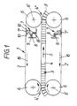
- the schematically illustrated double belt continuous casting mold 1 has, as the moving mold walls, an upper and lower endless casting belt 2 or 2 'and two laterally adjoining endless side dams 3, which are composed of individual elements 3' which are lined up in a mutually movable manner. While the approximately 1 mm thick casting belts 2, 2 'consist of carbon steel, the individual links 3' are made of a copper alloy.
- the mold walls 2, 2 'and 3 delimit a casting cavity 4 with a rectangular cross section, the inlet 4' and outlet 4 "of which are located on the left and right side of the continuous casting mold and through which the steel melt to be processed, which gradually solidifies, in the casting direction, ie in The direction of rotation of the mold walls - which in the area of the inlet 4 'and outlet 4 "each have deflection units in the form of deflection rollers 6 with fixed axes 6' or comparable deflection units (not shown) - is accordingly selected so that these move in the area of the casting cavity 4 in the same direction and at the same speed from left to right.
- test units 7 For continuous monitoring of the thermally and mechanically highly stressed casting belts 2 and 2 'for damage in the form of cracks, holes and the like, several ultrasound test units 7, each designed as a transmitter-receiver units, are arranged near the rear deflection rollers 6 in the circumferential direction Test heads 7 'lie in the casting belt area which executes the return movement opposite to the casting direction.
- the test units 7 are each assigned to the surface of the casting belt 2 or 2 ', which - in relation to the casting cavity 4 - forms the outer surface which does not come into contact with the molten steel: they are therefore within the endless path of the respective casting belt.
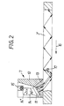
- Each test unit 7 is held on a stationary bracket 8 so as to be pivotable about a horizontal axis of rotation 9 and equipped with slide shoes 10 which, in the case of the upper casting belt 2, act under the action of a prestressed spring element 8 'or under the effect of their own weight (in the case of the lower one Support the casting belt 2 ') flexibly over a water film on the outer surface of the casting belt in question.
- the water film forms the coupling medium via which the test heads 7 'are connected to the associated casting belt in terms of sound technology; the associated water is supplied via spray openings (not shown) arranged in the sliding blocks 10 of the test units 7.
- the transmitters and receivers are arranged in the test heads 7 '; the receiver picks up the return signal damped by the casting belt 2 or 2 '; this differs markedly in the presence of damage which changes the damping effect from the return signal which arises when the transmission signal strikes the undamaged casting belt.
- the advantage associated with the use of test units operating according to the ultrasound method is, in particular, that the method of operation of the test device with regard to recording and evaluating measurement results can be automated, that the coating agent (coating) on the casting belts does not influence the fault detection, that the signal sequence of the test units casting speeds and consequently circulation speeds of the casting belts up to above 100 m / min. allows and that with appropriate alignment of the test heads, damage, in particular cracks, lying in different directions can also be determined.
- the known test units 7 basically consist of oscillating elements 11, which are supported on the side and enclosed by a damping housing 12 on a piezo element 13). At the same time, this forms the already mentioned slide shoe, under which a thin liquid cushion forms as a coupling medium during the casting operation.
- the return movement of the illustrated lower casting belt 2 ', which is opposite to the casting direction, is indicated by a dashed arrow 16.
- the defect which can be ascertained by means of the test unit 7 and which results in a different return signal is designated by 17.
- the lateral position of the test units 18 and 19 is expediently chosen so that the entire area of the casting belt which is particularly at risk — corresponding to the width of the casting cavity 4 (cf. FIG. 1) - is detected.
Landscapes
- Engineering & Computer Science (AREA)
- Mechanical Engineering (AREA)
- Continuous Casting (AREA)
- Investigating Or Analyzing Materials By The Use Of Ultrasonic Waves (AREA)
Claims (7)
Priority Applications (1)
| Application Number | Priority Date | Filing Date | Title |
|---|---|---|---|
| AT84112966T ATE31156T1 (de) | 1983-11-26 | 1984-10-27 | Pruefeinrichtung zur feststellung von beschaedigungen an den giessbaendern einer stranggiesskokille. |
Applications Claiming Priority (2)
| Application Number | Priority Date | Filing Date | Title |
|---|---|---|---|
| DE3342941A DE3342941C1 (de) | 1983-11-26 | 1983-11-26 | Pruefeinrichtung zur Feststellung von Beschaedigungen an den Giessbaendern einer Stranggiesskokille |
| DE3342941 | 1983-11-26 |
Publications (2)
| Publication Number | Publication Date |
|---|---|
| EP0143347A1 EP0143347A1 (fr) | 1985-06-05 |
| EP0143347B1 true EP0143347B1 (fr) | 1987-12-02 |
Family
ID=6215427
Family Applications (1)
| Application Number | Title | Priority Date | Filing Date |
|---|---|---|---|
| EP84112966A Expired EP0143347B1 (fr) | 1983-11-26 | 1984-10-27 | Dispositif d'essai pour la détermination de défauts sur les bandes de coulée d'un moule de coulée continue |
Country Status (5)
| Country | Link |
|---|---|
| US (1) | US4573521A (fr) |
| EP (1) | EP0143347B1 (fr) |
| JP (1) | JPS60133954A (fr) |
| AT (1) | ATE31156T1 (fr) |
| DE (1) | DE3342941C1 (fr) |
Families Citing this family (13)
| Publication number | Priority date | Publication date | Assignee | Title |
|---|---|---|---|---|
| DE3444689A1 (de) * | 1984-12-07 | 1986-01-16 | Fried. Krupp Gmbh, 4300 Essen | Fuehrungseinrichtung an den giessbaendern einer doppelbandstranggiesskokille |
| US5086827A (en) * | 1990-12-06 | 1992-02-11 | Hazelett Strip-Casting Corporation | Method and apparatus for sensing the condition of casting belt and belt coating in a continuous metal casting machine |
| DE102005001431B4 (de) * | 2005-01-12 | 2013-01-17 | Robert Bosch Gmbh | Zugmitteltrieb, Verfahren zur Erfassung des Verschleißes eines endlosen Zugmittels und endloses Zugmittel für einen solchen Zugmitteltrieb |
| US7298152B1 (en) | 2006-05-19 | 2007-11-20 | The Boeing Company | Damage detection system |
| DE102007057278A1 (de) * | 2007-08-04 | 2009-02-05 | Sms Demag Ag | Verfahren und Vorrichtung zur Vergleichmäßigung des Wärmeübergangs eines Gussprodukts während seiner Erstattung auf dem Metalltransportband einer horizontalen Bandgießanlage |
| US8594882B2 (en) * | 2008-01-16 | 2013-11-26 | The Boeing Company | Damage detection system |
| ATE539823T1 (de) | 2008-03-05 | 2012-01-15 | Southwire Co | Ultraschallsonde mit schutzschicht aus niobium |
| US8574336B2 (en) | 2010-04-09 | 2013-11-05 | Southwire Company | Ultrasonic degassing of molten metals |
| US8652397B2 (en) | 2010-04-09 | 2014-02-18 | Southwire Company | Ultrasonic device with integrated gas delivery system |
| JP6674376B2 (ja) | 2013-11-18 | 2020-04-01 | サウスワイヤー・カンパニー・リミテッド・ライアビリティ・カンパニーSouthwire Company,Llc | 溶融金属の脱ガス用排気口付き超音波プローブ |
| HUE048957T2 (hu) | 2015-02-09 | 2020-09-28 | Hans Tech Llc | Ultrahangos szemcsefinomítás |
| US10233515B1 (en) | 2015-08-14 | 2019-03-19 | Southwire Company, Llc | Metal treatment station for use with ultrasonic degassing system |
| EP3347150B1 (fr) | 2015-09-10 | 2020-08-19 | Southwire Company, LLC | Dispositif de raffinage de grains et de dégazage à ultrasons pour la coulée de métaux |
Family Cites Families (6)
| Publication number | Priority date | Publication date | Assignee | Title |
|---|---|---|---|---|
| BE576793A (fr) * | 1958-03-17 | |||
| CH443576A (de) * | 1966-07-14 | 1967-09-15 | Concast Ag | Verfahren und Vorrichtung zum Ankoppeln von Ultraschall an heisse Metalle, insbesondere beim Stranggiessen |
| CH479071A (de) * | 1966-12-13 | 1969-09-30 | Concast Ag | Vorrichtung zur Lokalisierung von Inhomogenitäten nach dem Ultraschall-Echo-Prinzip, insbesondere zur Bestimmung der Phasengrenze fest/flüssig beim Stranggiessen |
| DE2501868C3 (de) * | 1975-01-15 | 1978-08-03 | Mannesmann Ag, 4000 Duesseldorf | Verfahren zur Regelung und Überwachung des Stranggießens von Stahl |
| DE2923398C2 (de) * | 1979-06-06 | 1981-07-09 | Mannesmann AG, 4000 Düsseldorf | Vorrichtung zum Ausmessen einer gebogenen Stranggießkokille |
| JPS57171552A (en) * | 1981-04-14 | 1982-10-22 | Furukawa Electric Co Ltd:The | Continuous casting device |
-
1983
- 1983-11-26 DE DE3342941A patent/DE3342941C1/de not_active Expired
-
1984
- 1984-10-27 EP EP84112966A patent/EP0143347B1/fr not_active Expired
- 1984-10-27 AT AT84112966T patent/ATE31156T1/de not_active IP Right Cessation
- 1984-11-23 US US06/674,402 patent/US4573521A/en not_active Expired - Lifetime
- 1984-11-26 JP JP59248256A patent/JPS60133954A/ja active Pending
Also Published As
| Publication number | Publication date |
|---|---|
| EP0143347A1 (fr) | 1985-06-05 |
| DE3342941C1 (de) | 1984-12-06 |
| JPS60133954A (ja) | 1985-07-17 |
| US4573521A (en) | 1986-03-04 |
| ATE31156T1 (de) | 1987-12-15 |
Similar Documents
| Publication | Publication Date | Title |
|---|---|---|
| EP0143347B1 (fr) | Dispositif d'essai pour la détermination de défauts sur les bandes de coulée d'un moule de coulée continue | |
| DE69434208T2 (de) | Ultraschall Seitensichtvorrichtung für Schienenkopffehlerprüfung | |
| EP0685068B1 (fr) | Dispositif ultrasonore permettant de verifier des soudures effectuees sur des tuyaux, des toles et des contenants | |
| DE68916204T2 (de) | Verfahren und Vorrichtung zur genauen Einstellung eines Teiles, das quer entlang einer Schiene versetzt ist. | |
| DE69929664T2 (de) | Verfahren und Vorrichtung zum Erfassen von Fehlern in Bändern | |
| DE3223250C2 (de) | Verfahren und Einrichtung zum Identifizieren von Teilchen in einer Strömung | |
| DE2817474A1 (de) | Vorrichtung fuer die feststellung und ortung von fehlern in schweissnaehten vor ort | |
| DE1473722A1 (de) | Verfahren zur Materialpruefung laenglicher Prueflinge durch Ultraschall | |
| DE4027161C2 (fr) | ||
| DE69712741T2 (de) | Verfahren zum akustischen nachweis von fehlern einer laufenden materialbahn | |
| DE3627796C1 (en) | Device for monitoring the state and breakage of rotating tools by means of measurements of structure-borne sound | |
| DE3610484C2 (de) | Verfahren und Vorrichtung zum Bestimmen des Ortes von in Flachglas vorhandenen Fehlern | |
| DE2753635A1 (de) | Verfahren und vorrichtung zur automatischen ermittlung von rissen in schweisszonen, die in umfangsrichtung um ein rohr verlaufen | |
| DE3416709C2 (fr) | ||
| DE102013217101A1 (de) | Stranggießvorrichtung und Verfahren zur Produktion und/oder Inspektion von metallurgischen Gießprodukten | |
| DE4015847C2 (fr) | ||
| EP2052246A1 (fr) | Procede pour le controle de la structure d'un assemblage par soudure | |
| DE2238130C3 (de) | Verfahren zur Ermittlung und Kompensation von unterschiedlichen Schallschwächungseigenschaften bei der Ultraschall-Werkstoffprüfung | |
| EP2609421B1 (fr) | Réglage automatique de l'angle d'incidence d'une tête de contrôle à ultrasons, en fonction de sa position | |
| DE102016205548A1 (de) | Ultraschall-Prüfkopf und Ultraschall-Prüfanlage | |
| DE1773075A1 (de) | Ultraschallpruefverfahren fuer Ultraschallwinkelstrahl-Pruefgeraete mit Rueckstrahlblock | |
| WO2005073698A1 (fr) | Procede de determination de la profondeur d'un defaut dans une bande de verre | |
| DE2917510C2 (de) | Verfahren zur automatischen Erkennung der Breite, der Kopf- und der Seitenkonturen von blech- oder bandförmigen Prüfstücken bei der Werkstoffprüfung mit Ultraschall | |
| DE3444481C2 (fr) | ||
| DE60115677T2 (de) | Verfahren und Vorrichtung zur Fehlerprüfung bei der Herstellung von Plattenmaterialien |
Legal Events
| Date | Code | Title | Description |
|---|---|---|---|
| PUAI | Public reference made under article 153(3) epc to a published international application that has entered the european phase |
Free format text: ORIGINAL CODE: 0009012 |
|
| AK | Designated contracting states |
Designated state(s): AT BE CH FR GB IT LI LU NL SE |
|
| 17P | Request for examination filed |
Effective date: 19851107 |
|
| 17Q | First examination report despatched |
Effective date: 19860725 |
|
| GRAA | (expected) grant |
Free format text: ORIGINAL CODE: 0009210 |
|
| AK | Designated contracting states |
Kind code of ref document: B1 Designated state(s): AT BE CH FR GB IT LI LU NL SE |
|
| REF | Corresponds to: |
Ref document number: 31156 Country of ref document: AT Date of ref document: 19871215 Kind code of ref document: T |
|
| GBT | Gb: translation of ep patent filed (gb section 77(6)(a)/1977) | ||
| ET | Fr: translation filed | ||
| ITF | It: translation for a ep patent filed | ||
| PLBE | No opposition filed within time limit |
Free format text: ORIGINAL CODE: 0009261 |
|
| STAA | Information on the status of an ep patent application or granted ep patent |
Free format text: STATUS: NO OPPOSITION FILED WITHIN TIME LIMIT |
|
| PG25 | Lapsed in a contracting state [announced via postgrant information from national office to epo] |
Ref country code: LU Free format text: LAPSE BECAUSE OF NON-PAYMENT OF DUE FEES Effective date: 19881031 |
|
| 26N | No opposition filed | ||
| PGFP | Annual fee paid to national office [announced via postgrant information from national office to epo] |
Ref country code: FR Payment date: 19890915 Year of fee payment: 6 |
|
| PGFP | Annual fee paid to national office [announced via postgrant information from national office to epo] |
Ref country code: SE Payment date: 19890919 Year of fee payment: 6 |
|
| PGFP | Annual fee paid to national office [announced via postgrant information from national office to epo] |
Ref country code: LU Payment date: 19890920 Year of fee payment: 6 |
|
| PGFP | Annual fee paid to national office [announced via postgrant information from national office to epo] |
Ref country code: GB Payment date: 19890930 Year of fee payment: 6 |
|
| PGFP | Annual fee paid to national office [announced via postgrant information from national office to epo] |
Ref country code: CH Payment date: 19891011 Year of fee payment: 6 Ref country code: BE Payment date: 19891011 Year of fee payment: 6 |
|
| PGFP | Annual fee paid to national office [announced via postgrant information from national office to epo] |
Ref country code: AT Payment date: 19891030 Year of fee payment: 6 |
|
| ITTA | It: last paid annual fee | ||
| PGFP | Annual fee paid to national office [announced via postgrant information from national office to epo] |
Ref country code: NL Payment date: 19891031 Year of fee payment: 6 |
|
| REG | Reference to a national code |
Ref country code: GB Ref legal event code: 732 |
|
| ITPR | It: changes in ownership of a european patent |
Owner name: CESSIONE;MANNESMANN AG |
|
| REG | Reference to a national code |
Ref country code: CH Ref legal event code: PUE Owner name: MANNESMANN AKTIENGESELLSCHAFT |
|
| NLS | Nl: assignments of ep-patents |
Owner name: MANNESMANN AKTIENGESELLSCHAFT TE DUESSELDORF, BOND |
|
| REG | Reference to a national code |
Ref country code: FR Ref legal event code: TP |
|
| PG25 | Lapsed in a contracting state [announced via postgrant information from national office to epo] |
Ref country code: GB Effective date: 19901027 Ref country code: AT Effective date: 19901027 |
|
| PG25 | Lapsed in a contracting state [announced via postgrant information from national office to epo] |
Ref country code: SE Effective date: 19901028 |
|
| PG25 | Lapsed in a contracting state [announced via postgrant information from national office to epo] |
Ref country code: LI Effective date: 19901031 Ref country code: CH Effective date: 19901031 Ref country code: BE Effective date: 19901031 |
|
| BERE | Be: lapsed |
Owner name: FRIED. KRUPP G.M.B.H. Effective date: 19901031 |
|
| PG25 | Lapsed in a contracting state [announced via postgrant information from national office to epo] |
Ref country code: NL Effective date: 19910501 |
|
| NLV4 | Nl: lapsed or anulled due to non-payment of the annual fee | ||
| GBPC | Gb: european patent ceased through non-payment of renewal fee | ||
| PG25 | Lapsed in a contracting state [announced via postgrant information from national office to epo] |
Ref country code: FR Effective date: 19910628 |
|
| REG | Reference to a national code |
Ref country code: CH Ref legal event code: PL |
|
| REG | Reference to a national code |
Ref country code: FR Ref legal event code: ST |
|
| EUG | Se: european patent has lapsed |
Ref document number: 84112966.1 Effective date: 19910603 |