EP0143355A2 - Visionneuse portative - Google Patents
Visionneuse portative Download PDFInfo
- Publication number
- EP0143355A2 EP0143355A2 EP84113072A EP84113072A EP0143355A2 EP 0143355 A2 EP0143355 A2 EP 0143355A2 EP 84113072 A EP84113072 A EP 84113072A EP 84113072 A EP84113072 A EP 84113072A EP 0143355 A2 EP0143355 A2 EP 0143355A2
- Authority
- EP
- European Patent Office
- Prior art keywords
- window
- magnifying glass
- hand
- reader according
- film
- Prior art date
- Legal status (The legal status is an assumption and is not a legal conclusion. Google has not performed a legal analysis and makes no representation as to the accuracy of the status listed.)
- Withdrawn
Links
- 239000011521 glass Substances 0.000 claims abstract description 41
- 238000009499 grossing Methods 0.000 claims abstract description 8
- 238000004140 cleaning Methods 0.000 claims 1
- 239000011022 opal Substances 0.000 description 9
- 238000010276 construction Methods 0.000 description 4
- 239000000463 material Substances 0.000 description 2
- 230000003287 optical effect Effects 0.000 description 2
- 238000010073 coating (rubber) Methods 0.000 description 1
- 238000005286 illumination Methods 0.000 description 1
- 230000001795 light effect Effects 0.000 description 1
- 238000004519 manufacturing process Methods 0.000 description 1
- 238000000034 method Methods 0.000 description 1
- 230000004048 modification Effects 0.000 description 1
- 238000012986 modification Methods 0.000 description 1
- 239000005304 optical glass Substances 0.000 description 1
- 229920003229 poly(methyl methacrylate) Polymers 0.000 description 1
- 239000004926 polymethyl methacrylate Substances 0.000 description 1
- 230000004304 visual acuity Effects 0.000 description 1
Images
Classifications
-
- G—PHYSICS
- G02—OPTICS
- G02B—OPTICAL ELEMENTS, SYSTEMS OR APPARATUS
- G02B25/00—Eyepieces; Magnifying glasses
- G02B25/002—Magnifying glasses
- G02B25/005—Magnifying glasses with means for adjusting the magnifying glass or the object viewed
Definitions
- the invention relates to a handheld reader with magnifying glass for sheet films, e.g. Microfiche, consisting of a housing with a transport device engaging the sheet film for its linear movement relative to the magnifying glass.
- a handheld reader with magnifying glass for sheet films e.g. Microfiche
- Simple handheld readers have a fork-shaped housing with a joint in the apex, so that a flat film can be clamped between the two legs, one of which carries a magnifying glass near its free end, and held during reading.
- the main disadvantages of these simple devices are that the sheet film has no guidance when moving from one reading point to another, that when it is clamped to read an image near the bottom it is no longer held with its major part and therefore buckles, as above all that these devices with inserted sheet film cannot be temporarily put down and taken up again without the sheet film slipping relative to the magnifying glass.
- a relatively complicated hand-held reader in which the magnifying glass is fixedly mounted on the housing and the sheet film is inserted into a frame with an elongated window that can be inserted into the housing.
- the frame In order to bring various images on the sheet film into the beam path of the magnifying glass, on the one hand the frame can be gradually shifted in the longitudinal direction of its window, on the other hand the sheet film can be pulled or pushed in the transverse direction by hand through the guide slot in the frame.
- the invention is therefore based on the object to provide a hand-held reader of the type mentioned, which is of very simple construction and inexpensive to manufacture, but ensures a very sensitive adjustment of the image section to be viewed and its reliable holding under the lens when the device is temporarily removed.
- the housing forms an elongated window, along which the magnifying glass is displaceably guided and transversely to which the sheet film can be transported by conveyor elements arranged on both sides of the window.
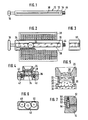
- the housing designated 1o consists of an upper part 12 and a lower part 14 shaped identically therewith.
- the two housing parts normally remain firmly connected to one another during use, e.g. by elastic snap engagement, but can be separated from one another for repair purposes.
- elastically locking connecting elements screws and other releasable fastening elements can of course also be used to connect the two housing parts 12 and 14.
- the housing 10 has the elongated flat shape shown in FIGS. 1 and 2, similar to a relatively thick ruler with a central opening extending almost over the entire length, which forms a window 16.
- a hammer-like handle 18 can be integrally formed on the housing 10 at at least one end.
- the longitudinal edges of the window 16 form longitudinal guides 20 for a small slide 22, which carries a magnifying glass designated overall by 24 and is displaceable along the window 16.
- the magnifying glass itself is preferably designed in two parts.
- the upper part designated 26 carries a plurality of lenses 28, preferably made of high-quality optical material, and can easily be unscrewed from the slide 22 in order to be easily exchangeable at a different magnification.
- the high-quality magnifying glass upper part 26 can also be used for purposes other than just the hand-held reader described.
- the normally multi-lens optical system of the magnifying glass also includes preferably from the upper part 26 separate magnifying glass base 0 0 , which can also consist, for example, of optical glass, but also of acrylic glass, for example, and forms the bottom lens of the lens system.
- the magnifying glass base 3o is smooth and even on the underside in the central region and is set back somewhat from the edge region which projects with 32 and projects downwards.
- an opal glass pane 34 is firmly connected to the lower housing part, e.g. glued.
- the opal glass provides a uniform illumination of the film material in the area under consideration in the manner customary for this application, without annoying light effects.
- the surface of the opal glass pane 34 is located approximately in the middle plane or parting line between the two housing halves 12 and 14, between which there is a transverse gap 36, which is approximately as long as the window 16 and leads across the housing, so that a in FIG 2 can be passed through 38 designated sheet film.
- the smoothing frame 32 of the base lens 3o can be guided parallel to the opal glass pane 34 with a very precisely set intermediate distance, so that a flat film just fits between these two parts 32 and 34.
- the flat films can have different strengths and, because of the desired constant visual acuity, the flat film should be guided and held as free of play as possible between the base lens 3o and the opal glass pane 34, it is preferable to press the base lens resiliently against the opal glass plate 34 by means of suitable spring members 36.
- the spring members 36 can Depending on the construction of the carriage 22, support it on this or on the upper housing part 12, as shown in FIG. 4. This also a desirable deceleration of the magnifying glass 24 results in the housing 1, 0, so that they do not unintentionally slip from a set position.
- the smoothing frame 32 is rounded or beveled in the manner shown, in order to avoid that when moving the magnifying glass along the window 16 or when passing the Flat film 38 through the slot 36 the film is scratched.
- a pair of transport rollers 40 , 42 is rotatably mounted in the housing.
- the two upper rollers 4o are driven synchronously and in the same direction by a handwheel 44 attached to the right end of the housing.
- the drive takes place via a gearwheel 46 connected to the handwheel 44 which, according to FIG. 6, engages with gearwheels 48 and 5o attached to the right ends of the transport rollers 4o in a rotationally fixed manner.
- the lower rollers 42 interacting with the upper transport rollers 4o only need to be freely rotatable pressure rollers, which can also be provided with a rubber coating or with a plurality of rubber rings to improve the friction.
- rollers 4 0, 42 of each roller pair are pressed against one another resiliently to the guided through between them sheet film to reliably detect and transport.
- a corresponding storage of the rollers is shown in Fig. 7.
- the journals 52, 54 sit at the ends of the rollers 4 0 , 42 in suitable grooves in the housing parts 12 and 14, respectively, such that the rollers are kept as free of play as possible except in the plane including their two central longitudinal axes.
- springs 56 and balls 58 are inserted into the grooves for the bearing journals 52 of the upper transport rollers 4o, which press against the axle journals 52 and thus the rollers 4o against the rollers 42.
- a handwheel 6o protruding from the housing at the top and / or bottom can also be provided according to FIG.
- the opal glass pane 34 does not extend over the entire length of the window 16, so that there is a free opening at the right and left end of the window.
- the length of these free openings is dimensioned such that whenever the magnifying glass 24 has been moved completely to the left or right end of the window 16, approximately one half of the base lens 3o protrudes laterally beyond the opal glass pane 34 and can be cleaned. However, the other half of the base lens 3o retains its resilient, elastic contact with the opal glass pane 34.
- identifiers for example letters, can be attached along the window 16 on the housing to designate the different columns of the images of the plan film.
- the various rows of images of the plan film can be identified on it itself with other identifiers, for example numbers.
- the arrangement of the transport rollers 4 0, 42 effected on both sides of the window 16 is a very linear guide of the sheet film while moving by means of the handwheel 44 or 6 0th This construction also has the advantage that the sheet film is held and guided securely even when the images on the edges of the sheet film are viewed with a magnifying glass.
Landscapes
- Physics & Mathematics (AREA)
- General Physics & Mathematics (AREA)
- Optics & Photonics (AREA)
- Lenses (AREA)
- Drawing Aids And Blackboards (AREA)
Applications Claiming Priority (2)
| Application Number | Priority Date | Filing Date | Title |
|---|---|---|---|
| DE8331483U | 1983-11-03 | ||
| DE8331483 | 1983-11-03 |
Publications (2)
| Publication Number | Publication Date |
|---|---|
| EP0143355A2 true EP0143355A2 (fr) | 1985-06-05 |
| EP0143355A3 EP0143355A3 (fr) | 1985-11-21 |
Family
ID=6758531
Family Applications (1)
| Application Number | Title | Priority Date | Filing Date |
|---|---|---|---|
| EP84113072A Withdrawn EP0143355A3 (fr) | 1983-11-03 | 1984-10-30 | Visionneuse portative |
Country Status (2)
| Country | Link |
|---|---|
| EP (1) | EP0143355A3 (fr) |
| DE (1) | DE8331483U1 (fr) |
Cited By (4)
| Publication number | Priority date | Publication date | Assignee | Title |
|---|---|---|---|---|
| EP0310337A1 (fr) * | 1987-09-29 | 1989-04-05 | The Quaker Oats Company | Visionneuse de région géographique sur un globe terrestre |
| FR2633403A1 (fr) * | 1988-06-22 | 1989-12-29 | Bayer Ag | Dispositif pour le diagnostic de maladies ou de parasites sur des parties de plantes |
| GB2285140A (en) * | 1993-12-24 | 1995-06-28 | Projectron Limited | Hand-held microfilm reader with microfilm clamp |
| DE19856182A1 (de) * | 1998-12-05 | 2000-06-08 | Michael Lange | Erkennungshilfe für Sehbehinderte |
Family Cites Families (5)
| Publication number | Priority date | Publication date | Assignee | Title |
|---|---|---|---|---|
| FR339231A (fr) * | 1903-12-23 | 1905-01-26 | Edmond Bloch | Procédé pour la préparation de plaques ou clichés positifs stéréoscopiques, et appareils pour la vision directe desdits clichés |
| US1411008A (en) * | 1920-11-20 | 1922-03-28 | Bradley A Fiske | Reading machine |
| US1457429A (en) * | 1922-01-30 | 1923-06-05 | Bradley A Fiske | Reading machine |
| FR2287709A2 (fr) * | 1974-10-11 | 1976-05-07 | Ciais Roger | Dispositif portatif de visualisation selective d'images microfilmees |
| US4257180A (en) * | 1979-10-22 | 1981-03-24 | Am International, Inc. | Microfiche viewer |
-
1983
- 1983-11-03 DE DE19838331483D patent/DE8331483U1/de not_active Expired
-
1984
- 1984-10-30 EP EP84113072A patent/EP0143355A3/fr not_active Withdrawn
Cited By (7)
| Publication number | Priority date | Publication date | Assignee | Title |
|---|---|---|---|---|
| EP0310337A1 (fr) * | 1987-09-29 | 1989-04-05 | The Quaker Oats Company | Visionneuse de région géographique sur un globe terrestre |
| FR2633403A1 (fr) * | 1988-06-22 | 1989-12-29 | Bayer Ag | Dispositif pour le diagnostic de maladies ou de parasites sur des parties de plantes |
| GB2285140A (en) * | 1993-12-24 | 1995-06-28 | Projectron Limited | Hand-held microfilm reader with microfilm clamp |
| US5572814A (en) * | 1993-12-24 | 1996-11-12 | Projectron Ltd. | Hand-held microfilm readers |
| GB2285140B (en) * | 1993-12-24 | 1997-02-26 | Projectron Limited | Hand-held microfilm readers |
| DE19856182A1 (de) * | 1998-12-05 | 2000-06-08 | Michael Lange | Erkennungshilfe für Sehbehinderte |
| DE19856182C2 (de) * | 1998-12-05 | 2002-11-07 | Michael Lange | Lesehilfsgerät für Sehbehinderte |
Also Published As
| Publication number | Publication date |
|---|---|
| DE8331483U1 (de) | 1984-02-02 |
| EP0143355A3 (fr) | 1985-11-21 |
Similar Documents
| Publication | Publication Date | Title |
|---|---|---|
| DE668315C (de) | Zeichenvorrichtung | |
| DE2053020B2 (de) | Praezisions-objektivisch fuer ein optisches mikroskop | |
| DE3410944C1 (de) | Gekapselte Meßeinrichtung | |
| EP0143355A2 (fr) | Visionneuse portative | |
| DE2652548B2 (de) | Photographisches Kopiergerät, insbesondere elektrophotographisches Kopiergerät mit hin- und hergehendem Vorlageträger | |
| DE2125105A1 (fr) | ||
| DE3421132C2 (de) | Übungs- und Untersuchungsgerät für die menschlichen Augen | |
| DE3119311A1 (de) | "vorrichtung zur drehbewegungsuebertragung" | |
| DE2736042C3 (de) | Lernhilfevorrichtung | |
| DE69103659T2 (de) | Tragbarer Drucker. | |
| DE2651822C2 (de) | Längenmeßgerät für bahnförmiges Meßgut | |
| DE3239515C2 (fr) | ||
| EP0066291B1 (fr) | Cadre pour diapositives | |
| DE720903C (de) | Projektionsvorrichtung, vorzugsweise fuer Karteikarten | |
| DE2610383A1 (de) | Lesegeraet zum lesbarmachen eines auf einem mikrofiche befindlichen mikrobildes | |
| DE1087367B (de) | Parallelogrammfuehrung fuer Objekttische | |
| DE2701097A1 (de) | Geraet zum abbilden eines gegenstandes in genauer zentralperspektive | |
| DE2951367C2 (de) | Halte- und Führungsvorrichtung für einen Mikrofiche an einem Mikrofilm-Lesegerät | |
| DE863550C (de) | Zeichnungsgeraet | |
| DE3046650A1 (de) | "diapositivprojektor" | |
| DE954569C (de) | Einrichtung zum Montieren von Stereo-Halbbildpaaren | |
| DE2914652A1 (de) | Verstellbares mikrofilmkartenlesegeraet | |
| DE819213C (de) | Reissbrett mit verstellbarer Zeichenflaeche | |
| DE1938771C3 (de) | Einrichtung zur Lageeinstellung von Geräten | |
| AT354898B (de) | Zeichenkopf fuer ein zeichengeraet |
Legal Events
| Date | Code | Title | Description |
|---|---|---|---|
| PUAI | Public reference made under article 153(3) epc to a published international application that has entered the european phase |
Free format text: ORIGINAL CODE: 0009012 |
|
| AK | Designated contracting states |
Designated state(s): DE FR GB IT SE |
|
| PUAL | Search report despatched |
Free format text: ORIGINAL CODE: 0009013 |
|
| AK | Designated contracting states |
Designated state(s): DE FR GB IT SE |
|
| 17P | Request for examination filed |
Effective date: 19851111 |
|
| 17Q | First examination report despatched |
Effective date: 19861223 |
|
| STAA | Information on the status of an ep patent application or granted ep patent |
Free format text: STATUS: THE APPLICATION HAS BEEN WITHDRAWN |
|
| 18W | Application withdrawn |
Withdrawal date: 19870627 |