EP0143376B1 - Dispositif d'extraction du contenu de récipients tels que sacs - Google Patents
Dispositif d'extraction du contenu de récipients tels que sacs Download PDFInfo
- Publication number
- EP0143376B1 EP0143376B1 EP84113492A EP84113492A EP0143376B1 EP 0143376 B1 EP0143376 B1 EP 0143376B1 EP 84113492 A EP84113492 A EP 84113492A EP 84113492 A EP84113492 A EP 84113492A EP 0143376 B1 EP0143376 B1 EP 0143376B1
- Authority
- EP
- European Patent Office
- Prior art keywords
- bag
- extracting
- container
- setting table
- film
- Prior art date
- Legal status (The legal status is an assumption and is not a legal conclusion. Google has not performed a legal analysis and makes no representation as to the accuracy of the status listed.)
- Expired
Links
- XAGFODPZIPBFFR-UHFFFAOYSA-N aluminium Chemical compound [Al] XAGFODPZIPBFFR-UHFFFAOYSA-N 0.000 description 3
- 229910052782 aluminium Inorganic materials 0.000 description 3
- 239000011888 foil Substances 0.000 description 3
- 239000000463 material Substances 0.000 description 3
- 239000008267 milk Substances 0.000 description 2
- 210000004080 milk Anatomy 0.000 description 2
- 235000013336 milk Nutrition 0.000 description 2
- 239000004698 Polyethylene Substances 0.000 description 1
- 230000002411 adverse Effects 0.000 description 1
- 239000002131 composite material Substances 0.000 description 1
- 238000010276 construction Methods 0.000 description 1
- 238000000605 extraction Methods 0.000 description 1
- 238000010030 laminating Methods 0.000 description 1
- 239000007788 liquid Substances 0.000 description 1
- 239000011087 paperboard Substances 0.000 description 1
- -1 polyethylene Polymers 0.000 description 1
- 229920000573 polyethylene Polymers 0.000 description 1
- 238000005096 rolling process Methods 0.000 description 1
- 238000000926 separation method Methods 0.000 description 1
Images
Classifications
-
- B—PERFORMING OPERATIONS; TRANSPORTING
- B65—CONVEYING; PACKING; STORING; HANDLING THIN OR FILAMENTARY MATERIAL
- B65B—MACHINES, APPARATUS OR DEVICES FOR, OR METHODS OF, PACKAGING ARTICLES OR MATERIALS; UNPACKING
- B65B69/00—Unpacking of articles or materials, not otherwise provided for
- B65B69/005—Unpacking of articles or materials, not otherwise provided for by expelling contents, e.g. by squeezing the container
-
- G—PHYSICS
- G03—PHOTOGRAPHY; CINEMATOGRAPHY; ANALOGOUS TECHNIQUES USING WAVES OTHER THAN OPTICAL WAVES; ELECTROGRAPHY; HOLOGRAPHY
- G03B—APPARATUS OR ARRANGEMENTS FOR TAKING PHOTOGRAPHS OR FOR PROJECTING OR VIEWING THEM; APPARATUS OR ARRANGEMENTS EMPLOYING ANALOGOUS TECHNIQUES USING WAVES OTHER THAN OPTICAL WAVES; ACCESSORIES THEREFOR
- G03B42/00—Obtaining records using waves other than optical waves; Visualisation of such records by using optical means
- G03B42/02—Obtaining records using waves other than optical waves; Visualisation of such records by using optical means using X-rays
- G03B42/04—Holders for X-ray films
- G03B42/045—Holders for X-ray films apparatus for loading or unloading the holders
Definitions
- This invention relates to an extracting device for extracting contents from a bag-like container, and more particularly to such an extracting device for extracting contents from a flexible bag-like container.
- An extracting device for extracting contents from a bag-like container is used in, for instance, an automatic loading system for automatically loading film such as X-ray film into a film magazine or a film cassette in a light room.
- a typical extracting device for an automatic film loading system is disclosed in Japanese Unexamined Patent Publication No. 54(1979)-143227.
- a light shielding bag accommodating therein X-ray film is supported in a predetermined position in a light-shielded chamber and the bag is severed between an end of the bag and the end of the film adjacent to the end of the bag.
- a pair of nip rollers sandwiching therebetween the other end of the bag are rotated, with the contents of the bag, i.e. the film, being held, to move the bag so that the film is extracted therefrom through the opening formed by severing said end.
- the extracted film is then supplied to a film magazine or a film cassette.
- This known extracting device is disadvantageous in that the structure is complicated since there are required a mechanism for pressing the nip rollers against each other so that a nipping pressure sufficient to move the bag away from the contents thereof is generated between the nip rollers, and a roller moving mechanism for moving the nip rollers away from each other in order to prepare for the next loading.
- JP-U-56 51 40 discloses an extracting device for a loading system for loading light sensitive films in a light room.
- That device is provided with a setting table, which is movable between a bag-placing position in which the flexible bag-like container can be placed on the setting table and an extracting position in which the bag-like container is to be removed from the content therein. Furthermore, the device is provided with a housing with respect to which the setting table is moved between the bag-placing position and the extracting position, wherein the setting table and the housing are forming a light shielding housing when the setting table is in the extracting position.
- the device also comprises drawing means carried by the setting table and the housing and consisting of first and second members which are opposed to each other with a portion of the bag-like container near one end thereof intervening therebetween when the setting table is in the extracting position.
- one end portion of the bag containing the film is sandwiched between the first and second members of the so- called drawing means in order to allow to draw backthe bag.
- the drawing step itself is carried out manually in that the end portion of the bag can be caught by the operator so that the bag can be pulled out manually of the extracting device.
- the first and second members are in the form of rollers, between which the bag is intervened. Therefore the rollers are merely used for stroking the bag so as to facilitate the separation of the film therefrom. They are not used for automatically extracting the bag or for transferring any extracting forces to the bag.
- first and second members in the form of the above-mentioned rollers are not driven by any driving means, but have been provided in order to reduce the resistance of the bag during the extraction process and to secure light shielding in order to prevent the light sensitive films within the housing from being exposed. Furthermore, the rollers are serving to prevent the contents of the bag from being removed from the housing.
- this extracting device is disadvantageous in that the setting table and the housing must be pressed against each other with a large force thereby adversely affecting the operation efficiency, since the film bag is formed by laminating aluminum foil and other materials for the purpose of providing light-shielding properties and humidity resistance to the film bag and therefore has rigidity to such an extent that the nip rollers must exert large nipping pressure to remove the bag from the contents thereof.
- US-PS 28 03 361 discloses an apparatus for emptying containers of liquid which is provided with a pair of gear-like members which are mounted on spaced, horizontal shafts and which are counter-rotated. Said two gear-like members are driven by driving gears which are fixed to the respective axis of said gear-like members.
- containers which are, for example, paper board milk containers, are fed to the roll gap which is formed by said two gear-like members.
- the toothed peripheries of said members grab the containers, pull them inwardly and, at the same time, crush them. This causes the containers to burst and the contents, for example milk, to be extruded.
- Said apparatus works like a mill which is performing a rolling process in which the containers, which are fed to the roll gap, are flattened.
- the toothed peripheries of said gear-like members being formed by gripping edges, are not meshing and only provided to grab the containers when entering the orbits of said gear-like members.
- the object underlying the invention is to provide an extracting device for extracting the contents of a bag-like container which is simple in construction and fail-safe in operation, and which has a high operation efficiency and is free from the drawbacks inherent to the known extracting devices.
- this object is solved in that the first and second members comprise one or more pairs of drivable gears which are meshed with each other with the said portion of the bag-like container intervening therebetween and that stopper means are provided for retaining the contents while drawing the container from the contents.
- a first extracting gear is mounted on a setting table for placing thereon a bag-like container.
- the setting table is movable with respect to a housing between a bag placing position in which the bag-like container is placed thereon, and an extracting position in which the contents of the container are extracted.
- the setting table and the housing form a light-shielded chamber.
- a second extracting gear which is adapted to be engaged with the first extracting gear with a portion of the bag-like container near one end thereof intervening therebetween when the setting table is moved to the extracting position.
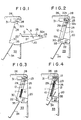
- FIGs 1 to 7 are schematic views illustrating the operation of a film loading system employing an extracting device in accordance with an embodiment of the present invention.
- a plurality of unexposed film (e.g. X-ray film) sheets 10 to be loaded by the film loading system shown in Figures 1 to 7 are stacked between the upper leaf and the lower leaf of a backboard member 11 formed by folding board material.
- the unexposed film sheets 10 together with the backboard member 11 are accommodated in a light-shielding flexible bag 12 formed of a laminated sheet material consisting of aluminum foil and polyethylene sheet.
- a pair of elongated notches 11 a are formed on respective side edges of the backboard member 11, and a pair of small notches 10a are formed on respective side edges of each film sheet 10 so that the small notches 10a of the film sheets 10 are positioned in the elongated notches 11 a of the backboard member 11 when the stack of the film sheets 10 are accommodated between the upper leaf and the lower leaf of the backboard member 11.
- a light shielding lid 20 of the system When film is loaded, a light shielding lid 20 of the system is first opened as shown in Figure 1, and the bag 12 with the film sheets 10 therein is placed on a flat setting table 21 fixed to the inner face of the light shielding lid 20.
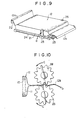
- the setting table 21 is provided with a cutter receiving groove 22 formed along one end thereof and a first extracting gear 23 extending along the other end thereof ( Figure 9).
- the bag 12 is placed on the setting table 21 so that a portion 12a near one end (referred to hereinbelow as the first end) of the bag 12 lies above the cutter receiving groove 22 over the entire width thereof and a portion near the other end (referred to hereinbelow as the second end) of the bag 12 lies on the first extracting gear 23.
- a pair of rods 24 extend along respective side edges, and a pair of holders 25 are supported on the respective rods 24 for rotation in the direction of the arrow B in Figure 9 and for sliding movement along the rods 24.
- the holders 25 are brought into the upright position shown in Figure 9 by a driving device to be engaged with the notches 10a and 11 respectively formed in the film sheets 10 and the backboard member 11 over the bag 12, thereby positioning the bag 12, the film sheets 10 and the backboard member 11 on the setting table 21.
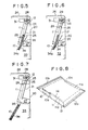
- a film loading chamber 27 shielded from ambient light is formed by the setting table 21 and a housing 26 of the system as shown in Figure 2.
- the housing 26 is provided with a second extracting gear 28 extending in parallel to the first extracting gear 23 on the setting table.
- the housing 26 is provided with a pressure roll 29 for flattening the film sheets 10 against the setting table 21 so that the film sheets 10 can be supported and fixed by the holders 25 even if the film sheets 10 curl.
- a cutter 20 is moved along the cutter receiving groove 22 in the housing 26 to sever the bag 12 along the portion 12a near the first end thereof.
- a gear driving device 31 is actuated to rotate the first and second extracting gears 23 and 28 in the direction of the arrows C in Figure 10, and the bag 12 is moved rightward as seen in Figure 10 away from the film sneets 10.
- the film sheets 10 in the bag 12 are fixedly supported on the setting table 21 by virtue of the holders 25 and the pressure roll 29, and are held by stoppers 32a and 32b which are adapted to pinch, when the light shielding lid 20 is closed, the bag 12 at a portion between the portion 12b sandwiched by the extracting gears 23 and 28 and the end of the film sheets 10 adjacent to the portion 12b. Therefore, the film sheets 10 cannot be moved together with the bag 12, thereby permitting the bag 12 to be moved away from the film sheets 10 by rotating the extracting gears 23 and 28.
- the bag 12 is formed of a composite material comprising aluminum foil and the like and therefore has rigidity to some extent, a large drawing force must be applied to the bag 12 in order to remove it from the film sheets 10.
- the drawing force for removing the bag from the film sheets is exerted by a pair of nip rollers respectively carried by the light shielding lid and the housing, the light shielding lid must be pressed against the housing at a high pressure in order to obtain sufficient drawing force by the nip rollers.
- a tray 34 movably disposed in a film chamber 33 in which the film sheets 10 are to be loaded is moved upwardly into the film loading chamber 27 raising a shutter 35 between the film chamber 33 and the film loading chamber 27 as shown in Figure 4.
- the holders 25 engaged with the small notches 10a of the film sheets 10 are slid downwardly along the rods 24 together with the pressure roll 29 driven by the driving device (not shown) to push the film sheets 10 until the lower ends of the film sheets 10 abut against a bottom flange 34a of the tray 34. Since the holders 25 move in the elongated notches 11 a of the backboard member 11 at this time, the backboard member 11 cannot be pushed together with the film sheets 10 and only the film sheets 10 are pushed into the tray 34.
- the holders 25 are swung outwardly to the horizontal position as seen in Figure 9, and the holders 25 and the pressure roll 29 are moved upwardly to the original position as shown in Figure 6. Then the tray 34 is returned to the original position in the film chamber 33 to permit the shutter 35 to be closed again as shown in Figure 7, thereby completing the loading operation.
- the loaded film sheets 10 may be fed to the next step by known means such as a vacuum sheeting device.
- the cut-off portion of the bag 12 and the bag 12 removed from the film sheets 10 are removed from the film loading chamber 27 after the film loading is completed and before the next film loading operation, with the backboard member 11 being removed simultaneously.
- the bag 12 is initially sealed at both ends thereof and is cut along the first end 12a prior to removal from the film sheets 10, the bag may be of a type which is not sealed at one end in advance and is folded at the end to make the end light-shielded.
- the extracting gears 23 and 28 are driven by the gear driving device 31 in the above embodiment, the extracting gears 23 and 28 may be manually driven.
- the lengths of the extracting gears 23 and 28 are substantially equal to the width of the bag 12 in the above embodiment, the extracting gears 23 and 28 may be shorter than the width of the bag 12 so that they nip only a part of the bag 12, or a plurality of pairs of extracting gears may be provided to nip the bag 12 at a plurality of positions arranged in a row in the direction of the width of the bag 12. Furthermore, a plurality of pairs of extracting gears, each having a length substantially equal to the width of the bag may be provided, if desired. Further, the present invention can be applied to any extracting device for extracting contents from a flexible bag-like container and is not limited to those for use in a film loading system or to those for extracting film sheets accommodated together with a backboard member in a flexible bag.
Landscapes
- Physics & Mathematics (AREA)
- General Physics & Mathematics (AREA)
- Engineering & Computer Science (AREA)
- Mechanical Engineering (AREA)
- Radiography Using Non-Light Waves (AREA)
- Discharge By Other Means (AREA)
- Sheets, Magazines, And Separation Thereof (AREA)
Claims (4)
Applications Claiming Priority (2)
| Application Number | Priority Date | Filing Date | Title |
|---|---|---|---|
| JP58210531A JPS60102338A (ja) | 1983-11-09 | 1983-11-09 | 包袋抜取装置 |
| JP210531/83 | 1983-11-09 |
Publications (2)
| Publication Number | Publication Date |
|---|---|
| EP0143376A1 EP0143376A1 (fr) | 1985-06-05 |
| EP0143376B1 true EP0143376B1 (fr) | 1988-02-03 |
Family
ID=16590898
Family Applications (1)
| Application Number | Title | Priority Date | Filing Date |
|---|---|---|---|
| EP84113492A Expired EP0143376B1 (fr) | 1983-11-09 | 1984-11-08 | Dispositif d'extraction du contenu de récipients tels que sacs |
Country Status (4)
| Country | Link |
|---|---|
| US (1) | US4571140A (fr) |
| EP (1) | EP0143376B1 (fr) |
| JP (1) | JPS60102338A (fr) |
| DE (1) | DE3469156D1 (fr) |
Families Citing this family (19)
| Publication number | Priority date | Publication date | Assignee | Title |
|---|---|---|---|---|
| US4625497A (en) * | 1985-09-17 | 1986-12-02 | Owen Tri-Cut Limited | Method and apparatus for extracting the contents of envelopes |
| JP2983992B2 (ja) * | 1988-09-01 | 1999-11-29 | 日本テトラパック株式会社 | 包装容器用ブランクの移送装置 |
| JPH047222A (ja) * | 1990-04-25 | 1992-01-10 | Fuji Photo Film Co Ltd | フイルム用マガジン |
| US5019848A (en) * | 1990-07-25 | 1991-05-28 | Eastman Kodak Company | Magazine for a stack of film sheets |
| US5055869A (en) * | 1990-07-25 | 1991-10-08 | Eastman Kodak Company | Film supply magazine |
| US5199569A (en) * | 1991-12-06 | 1993-04-06 | Eastman Kodak Company | Package for sheets of X-ray film |
| JP3096786B2 (ja) * | 1992-01-16 | 2000-10-10 | 株式会社リコー | 挿入された用紙パツクの包装シートを除去可能な画像形成装置の給紙装置 |
| US5257057A (en) * | 1992-06-22 | 1993-10-26 | Eastman Kodak Company | Magazine for a stack of film sheets |
| JP2742511B2 (ja) * | 1994-10-17 | 1998-04-22 | 富士写真フイルム株式会社 | 感光材料装填用マガジン |
| US5660384A (en) * | 1994-11-23 | 1997-08-26 | Minnesota Mining And Manufacturing Company | Imaging unit container having shiftable walls |
| US5560597A (en) * | 1994-11-23 | 1996-10-01 | Harris Corporation | Imaging unit container including bag clamping member |
| WO1998002787A1 (fr) | 1996-07-11 | 1998-01-22 | Cycolor, Inc. | Procede d'impression d'images a l'aide d'un film pack comprenant un rabat predecoupe |
| JP4323054B2 (ja) * | 2000-03-17 | 2009-09-02 | 富士フイルム株式会社 | 開封装置 |
| US6705818B2 (en) * | 2000-03-17 | 2004-03-16 | Fuji Photo Film Co., Ltd. | Package take-out apparatus, package container thereof and unwrapping apparatus |
| FR2866016B1 (fr) * | 2004-02-06 | 2007-03-30 | Erea Sa | Procede et dispositif de manutention, permettant de vider des conteneurs |
| JP2006053362A (ja) * | 2004-08-12 | 2006-02-23 | Konica Minolta Medical & Graphic Inc | 感光材料包装体の製造方法及び感光材料包装体 |
| FI124079B (fi) | 2011-09-02 | 2014-03-14 | Pro Hydro Ab Oy | Elastisen pakkaussäiliön purkauslaite ja menetelmä elastisen säiliön purkamiseksi |
| JP6610294B2 (ja) * | 2016-01-28 | 2019-11-27 | コニカミノルタ株式会社 | 収容装置および画像形成装置 |
| CN116767694B (zh) * | 2022-10-19 | 2025-11-11 | 北京海明威博技术开发有限公司 | 一种自动输出连续式棉签包装袋内的棉签的装置 |
Family Cites Families (7)
| Publication number | Priority date | Publication date | Assignee | Title |
|---|---|---|---|---|
| US2803361A (en) * | 1954-06-28 | 1957-08-20 | Nat Dairy Prod Corp | Apparatus for emptying containers of liquid |
| JPS5043740U (fr) * | 1973-08-17 | 1975-05-02 | ||
| JPS54143227A (en) * | 1978-04-28 | 1979-11-08 | Konishiroku Photo Ind Co Ltd | Film opener |
| JPS5552049A (en) * | 1978-10-13 | 1980-04-16 | Koichi Nishimura | Automatic feeding and receiving of x-ray film |
| JPS5647631Y2 (fr) * | 1979-06-22 | 1981-11-07 | ||
| JPS5642673U (fr) * | 1979-09-10 | 1981-04-18 | ||
| JPS5643796U (fr) * | 1979-09-11 | 1981-04-21 |
-
1983
- 1983-11-09 JP JP58210531A patent/JPS60102338A/ja active Pending
-
1984
- 1984-11-06 US US06/668,883 patent/US4571140A/en not_active Expired - Lifetime
- 1984-11-08 DE DE8484113492T patent/DE3469156D1/de not_active Expired
- 1984-11-08 EP EP84113492A patent/EP0143376B1/fr not_active Expired
Also Published As
| Publication number | Publication date |
|---|---|
| DE3469156D1 (en) | 1988-03-10 |
| EP0143376A1 (fr) | 1985-06-05 |
| JPS60102338A (ja) | 1985-06-06 |
| US4571140A (en) | 1986-02-18 |
Similar Documents
| Publication | Publication Date | Title |
|---|---|---|
| EP0143376B1 (fr) | Dispositif d'extraction du contenu de récipients tels que sacs | |
| CN1021646C (zh) | 装有受压柔性物品的易开式软包及其制造方法和设备 | |
| BE1005517A5 (fr) | Appareil de fabrication de sacs avec separateur-plieur. | |
| EP0006780B1 (fr) | Changeur de feuilles de film nu précoupé et appareil de radiodiagnostic comportant un tel changeur | |
| US3780608A (en) | Strip cutting and mounting apparatus | |
| CA2045897A1 (fr) | Methode et appareil de conditionnement d'articles souples deformables | |
| EP1279603A1 (fr) | Distributeur pour des filtres emballés | |
| EP0376007A1 (fr) | Machine de fabrication de sacs à porter à poignées incorporées et pièces de renforcements en matière thermoplastique soudés autour de celles-ci | |
| US3968926A (en) | Tearstrip package | |
| JP2837977B2 (ja) | マガジン | |
| CN116461774B (zh) | 用于在转换机中存储片材堆的设备 | |
| JP3929526B2 (ja) | ラベル処理方法 | |
| JP2760557B2 (ja) | 紙葉類の束処理装置 | |
| JP3148299B2 (ja) | X線長尺フィルムの自動開封装置 | |
| JPH08184907A (ja) | フィルム・ユニットを輸送、現像し、その廃棄物を再循環すべく処理するシステム | |
| EP0718683B1 (fr) | Procédé pour emballer, de façon opaque, une pile de feuilles photosensibles, rectangulaires, et pour les charger en plein jour dans une armoire étanche à la lumière | |
| EP0524383A2 (fr) | Magasin d'alimentation de film | |
| JPH05213525A (ja) | 開封方法およびその開封装置 | |
| JPS6045106A (ja) | 包装装置 | |
| JPH0543103A (ja) | 自動原稿送り装置 | |
| DE1919948U (de) | Vorrichtung zur verpackung eines stapels von blaettern. | |
| JPH0451036A (ja) | X線長尺フィルムの自動開封装置 | |
| JP2001075248A (ja) | インスタント写真フイルムユニットの製造方法および装置 | |
| JPS63295246A (ja) | 包装袋製造方法およびその装置 | |
| JPH06321412A (ja) | 自動封緘機におけるフィルム送給制御方法 |
Legal Events
| Date | Code | Title | Description |
|---|---|---|---|
| PUAI | Public reference made under article 153(3) epc to a published international application that has entered the european phase |
Free format text: ORIGINAL CODE: 0009012 |
|
| AK | Designated contracting states |
Designated state(s): DE FR NL |
|
| 17P | Request for examination filed |
Effective date: 19851204 |
|
| 17Q | First examination report despatched |
Effective date: 19860707 |
|
| GRAA | (expected) grant |
Free format text: ORIGINAL CODE: 0009210 |
|
| AK | Designated contracting states |
Kind code of ref document: B1 Designated state(s): DE FR NL |
|
| REF | Corresponds to: |
Ref document number: 3469156 Country of ref document: DE Date of ref document: 19880310 |
|
| ET | Fr: translation filed | ||
| RIN2 | Information on inventor provided after grant (corrected) |
Free format text: YAMADA,SADAMI C/O FUJI PHOTO FILM CO., LTD. * TAMURA, KAORU C/O FUJI PHOTO FILM CO., LTD. |
|
| PLBE | No opposition filed within time limit |
Free format text: ORIGINAL CODE: 0009261 |
|
| STAA | Information on the status of an ep patent application or granted ep patent |
Free format text: STATUS: NO OPPOSITION FILED WITHIN TIME LIMIT |
|
| 26N | No opposition filed | ||
| PGFP | Annual fee paid to national office [announced via postgrant information from national office to epo] |
Ref country code: FR Payment date: 20021119 Year of fee payment: 19 |
|
| PGFP | Annual fee paid to national office [announced via postgrant information from national office to epo] |
Ref country code: NL Payment date: 20021125 Year of fee payment: 19 |
|
| PGFP | Annual fee paid to national office [announced via postgrant information from national office to epo] |
Ref country code: DE Payment date: 20021227 Year of fee payment: 19 |
|
| PG25 | Lapsed in a contracting state [announced via postgrant information from national office to epo] |
Ref country code: NL Free format text: LAPSE BECAUSE OF NON-PAYMENT OF DUE FEES Effective date: 20040601 |
|
| PG25 | Lapsed in a contracting state [announced via postgrant information from national office to epo] |
Ref country code: DE Free format text: LAPSE BECAUSE OF NON-PAYMENT OF DUE FEES Effective date: 20040602 |
|
| PG25 | Lapsed in a contracting state [announced via postgrant information from national office to epo] |
Ref country code: FR Free format text: LAPSE BECAUSE OF NON-PAYMENT OF DUE FEES Effective date: 20040730 |
|
| NLV4 | Nl: lapsed or anulled due to non-payment of the annual fee |
Effective date: 20040601 |
|
| REG | Reference to a national code |
Ref country code: FR Ref legal event code: ST |