EP0143427A2 - Procédé et appareil pour le contrôle d'un système de liquéfaction par ablation - Google Patents
Procédé et appareil pour le contrôle d'un système de liquéfaction par ablation Download PDFInfo
- Publication number
- EP0143427A2 EP0143427A2 EP84114057A EP84114057A EP0143427A2 EP 0143427 A2 EP0143427 A2 EP 0143427A2 EP 84114057 A EP84114057 A EP 84114057A EP 84114057 A EP84114057 A EP 84114057A EP 0143427 A2 EP0143427 A2 EP 0143427A2
- Authority
- EP
- European Patent Office
- Prior art keywords
- vessel
- combustion
- melting surface
- pulverulent material
- primary
- Prior art date
- Legal status (The legal status is an assumption and is not a legal conclusion. Google has not performed a legal analysis and makes no representation as to the accuracy of the status listed.)
- Granted
Links
- 238000000034 method Methods 0.000 title claims abstract description 40
- 238000002679 ablation Methods 0.000 title abstract description 4
- 230000008569 process Effects 0.000 title description 11
- 238000002485 combustion reaction Methods 0.000 claims abstract description 31
- 238000010438 heat treatment Methods 0.000 claims abstract description 9
- 239000000463 material Substances 0.000 claims description 53
- 238000002844 melting Methods 0.000 claims description 37
- 230000008018 melting Effects 0.000 claims description 37
- 239000006066 glass batch Substances 0.000 claims description 14
- 239000000567 combustion gas Substances 0.000 claims description 5
- 238000004886 process control Methods 0.000 abstract description 3
- 230000001052 transient effect Effects 0.000 description 16
- 239000007789 gas Substances 0.000 description 7
- 238000010309 melting process Methods 0.000 description 6
- XLYOFNOQVPJJNP-UHFFFAOYSA-N water Substances O XLYOFNOQVPJJNP-UHFFFAOYSA-N 0.000 description 4
- 239000011521 glass Substances 0.000 description 3
- 238000009413 insulation Methods 0.000 description 3
- 239000007788 liquid Substances 0.000 description 3
- 239000002994 raw material Substances 0.000 description 3
- 239000011819 refractory material Substances 0.000 description 3
- IJGRMHOSHXDMSA-UHFFFAOYSA-N Atomic nitrogen Chemical compound N#N IJGRMHOSHXDMSA-UHFFFAOYSA-N 0.000 description 2
- QVGXLLKOCUKJST-UHFFFAOYSA-N atomic oxygen Chemical compound [O] QVGXLLKOCUKJST-UHFFFAOYSA-N 0.000 description 2
- 239000000919 ceramic Substances 0.000 description 2
- 239000000470 constituent Substances 0.000 description 2
- 230000003247 decreasing effect Effects 0.000 description 2
- 239000000428 dust Substances 0.000 description 2
- -1 e.g. Substances 0.000 description 2
- 230000003628 erosive effect Effects 0.000 description 2
- 230000001788 irregular Effects 0.000 description 2
- 238000013021 overheating Methods 0.000 description 2
- 239000001301 oxygen Substances 0.000 description 2
- 229910052760 oxygen Inorganic materials 0.000 description 2
- 239000007787 solid Substances 0.000 description 2
- 238000011144 upstream manufacturing Methods 0.000 description 2
- 229910000831 Steel Inorganic materials 0.000 description 1
- 230000009471 action Effects 0.000 description 1
- 239000003570 air Substances 0.000 description 1
- 239000012080 ambient air Substances 0.000 description 1
- 230000015572 biosynthetic process Effects 0.000 description 1
- 239000004568 cement Substances 0.000 description 1
- 229910010293 ceramic material Inorganic materials 0.000 description 1
- 239000005356 container glass Substances 0.000 description 1
- 238000011109 contamination Methods 0.000 description 1
- 238000001816 cooling Methods 0.000 description 1
- 239000006063 cullet Substances 0.000 description 1
- 230000006866 deterioration Effects 0.000 description 1
- 238000005265 energy consumption Methods 0.000 description 1
- 239000011152 fibreglass Substances 0.000 description 1
- 238000010304 firing Methods 0.000 description 1
- 239000005357 flat glass Substances 0.000 description 1
- 230000009969 flowable effect Effects 0.000 description 1
- 239000012530 fluid Substances 0.000 description 1
- 230000004907 flux Effects 0.000 description 1
- 239000000446 fuel Substances 0.000 description 1
- 238000005816 glass manufacturing process Methods 0.000 description 1
- 239000008187 granular material Substances 0.000 description 1
- 229910052500 inorganic mineral Inorganic materials 0.000 description 1
- 239000011810 insulating material Substances 0.000 description 1
- 239000012212 insulator Substances 0.000 description 1
- 239000002184 metal Substances 0.000 description 1
- 229910052751 metal Inorganic materials 0.000 description 1
- 238000010310 metallurgical process Methods 0.000 description 1
- 150000002739 metals Chemical class 0.000 description 1
- 239000011707 mineral Substances 0.000 description 1
- 229910052757 nitrogen Inorganic materials 0.000 description 1
- 238000010298 pulverizing process Methods 0.000 description 1
- 238000009877 rendering Methods 0.000 description 1
- 230000004044 response Effects 0.000 description 1
- NTHWMYGWWRZVTN-UHFFFAOYSA-N sodium silicate Chemical compound [Na+].[Na+].[O-][Si]([O-])=O NTHWMYGWWRZVTN-UHFFFAOYSA-N 0.000 description 1
- 230000003068 static effect Effects 0.000 description 1
- 239000010959 steel Substances 0.000 description 1
Images
Classifications
-
- C—CHEMISTRY; METALLURGY
- C03—GLASS; MINERAL OR SLAG WOOL
- C03B—MANUFACTURE, SHAPING, OR SUPPLEMENTARY PROCESSES
- C03B5/00—Melting in furnaces; Furnaces so far as specially adapted for glass manufacture
- C03B5/16—Special features of the melting process; Auxiliary means specially adapted for glass-melting furnaces
- C03B5/235—Heating the glass
-
- C—CHEMISTRY; METALLURGY
- C03—GLASS; MINERAL OR SLAG WOOL
- C03B—MANUFACTURE, SHAPING, OR SUPPLEMENTARY PROCESSES
- C03B5/00—Melting in furnaces; Furnaces so far as specially adapted for glass manufacture
- C03B5/14—Melting in furnaces; Furnaces so far as specially adapted for glass manufacture in revolving cylindrical furnaces
-
- C—CHEMISTRY; METALLURGY
- C03—GLASS; MINERAL OR SLAG WOOL
- C03B—MANUFACTURE, SHAPING, OR SUPPLEMENTARY PROCESSES
- C03B5/00—Melting in furnaces; Furnaces so far as specially adapted for glass manufacture
- C03B5/16—Special features of the melting process; Auxiliary means specially adapted for glass-melting furnaces
- C03B5/235—Heating the glass
- C03B5/2353—Heating the glass by combustion with pure oxygen or oxygen-enriched air, e.g. using oxy-fuel burners or oxygen lances
-
- Y—GENERAL TAGGING OF NEW TECHNOLOGICAL DEVELOPMENTS; GENERAL TAGGING OF CROSS-SECTIONAL TECHNOLOGIES SPANNING OVER SEVERAL SECTIONS OF THE IPC; TECHNICAL SUBJECTS COVERED BY FORMER USPC CROSS-REFERENCE ART COLLECTIONS [XRACs] AND DIGESTS
- Y02—TECHNOLOGIES OR APPLICATIONS FOR MITIGATION OR ADAPTATION AGAINST CLIMATE CHANGE
- Y02P—CLIMATE CHANGE MITIGATION TECHNOLOGIES IN THE PRODUCTION OR PROCESSING OF GOODS
- Y02P40/00—Technologies relating to the processing of minerals
- Y02P40/50—Glass production, e.g. reusing waste heat during processing or shaping
-
- Y—GENERAL TAGGING OF NEW TECHNOLOGICAL DEVELOPMENTS; GENERAL TAGGING OF CROSS-SECTIONAL TECHNOLOGIES SPANNING OVER SEVERAL SECTIONS OF THE IPC; TECHNICAL SUBJECTS COVERED BY FORMER USPC CROSS-REFERENCE ART COLLECTIONS [XRACs] AND DIGESTS
- Y02—TECHNOLOGIES OR APPLICATIONS FOR MITIGATION OR ADAPTATION AGAINST CLIMATE CHANGE
- Y02P—CLIMATE CHANGE MITIGATION TECHNOLOGIES IN THE PRODUCTION OR PROCESSING OF GOODS
- Y02P40/00—Technologies relating to the processing of minerals
- Y02P40/50—Glass production, e.g. reusing waste heat during processing or shaping
- Y02P40/57—Improving the yield, e-g- reduction of reject rates
Definitions
- the present invention relates to controlling conditions within a chamber for converting pulverulent raw materials to a liquefied state as a first step in a melting process.
- the invention is generally applicable to processes that involve thermally converting a generally flowable, essentially solid state feed material to a molten fluid.
- the invention is particularly applicable to melting a transient layer of the material supported by a stable layer of granular, thermally insulating, non-contaminating material, e.g., liquefying a layer of glass batch supported by a layer of material such as a granular batch constituent or glass batch.
- U.S. Patent No. 4,381,934 to Kunkle et al. teaches a method of converting particulate batch materials to a partially melted, liquefied state on a support surface of batch material within a melting chamber.
- the initial process of liquefying'batch material is isolated from the remainder of the melting process and is carried out in a manner uniquely suited to the needs of the particular step, thereby permitting the liquefaction step to be carried out with considerable economies in energy consumption and equipment size and cost.
- thermal energy input is used to perform only the particular liquefaction step, the relationship between this input and other operating parameters is more direct and generally less complex than in a conventional tank-type melting furnace.
- a drum portion of the melting chamber is mounted for rotation so that batch fed into the chamber is held against chamber side walls by rotation of the drum to maintain a stable layer along the interior of the drum.
- Thermal energy is supplied to the drum interior so that the batch layer encircles the heat source.
- the liquefaction process is carried out by feeding batch into the drum through a stationary lid while rotating the drum and supplying heat to the drum interior to melt incoming batch material in a transient layer while an underlying layer of batch remains substantially stable and unmelted. As the material is liquefied, it flows downward toward an exit end of the rotating drum.
- a non- contaminating, thermally insulating layer of granular material e.g., glass batch itself
- a steady state condition may be maintained in the liquefaction chamber by distributing fresh batch onto a previously deposited batch surface at essentially the same rate at which the batch is melting, whereby a substantially stable batch layer will be maintained beneath a transient batch layer, and liquefaction is essentially confined to the transient layer.
- the partially melted batch of the transient layer runs off the surface while contacting substantially only a batch surface, thus avoiding contaminating contact with refractories. Because glass batch is a good heat insulator, providing the stable batch layer with sufficient thickness protects any underlying support structure from thermal deterioration.
- the present invention relates to a method of and apparatus for controlling conditions within a melting chamber of the type which utilizes a stable layer of granular, thermally insulating material, e.g., glass batch material, for supporting a transient layer of melting batch material during liquefaction of the material.
- a stable layer of granular, thermally insulating material e.g., glass batch material
- the invention is advantageously practiced for controlling an ablation liquefaction process in which the stable batch layer encircles a radiant heat source.
- the invention relates to a method of and apparatus for providing radiant energy to the chamber interior such that the radiant energy impinges upon the transient batch layer in a substantially uniform manner to substantially confine the melting process to melting the transient layer to maintain the stable batch layer within the desired thickness range throughout the melter interior.
- the invention includes facilities for selectively heating portions of the chamber interior for process control of product temperature and/or localized pressure gradients within the chamber.
- the preferred embodiment of the present invention relates to an ablation liquefaction process such as that taught in U.S. Patent No. 4,381,934 to Kunkle et al., the teachings of which are hereby incorporated by reference.
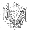
- the melter 10 may include a steel drum 12 having stepped sidewalls so as to decrease the amount of mass being rotated.
- the drum 12 is supported on a circular frame 14 which is, in turn, mounted for rotation about a generally vertical axis, corresponding to the centerline or axis of symmetry of the drum, on a plurality of support rollers 16 and aligning rollers 18.
- a bottom section 20 may be detachably secured to the drum 12.
- the bottom section 20 may be lined with an annulus of refractory material 22 such as castable refractory cement in which is seated a ring-like bushing 24 of an erosion resistant refractory material.
- the bushing 24 may be comprised of a plurality of cut pieces of ceramic.
- An open center 26 in the bushing 24 comprises the outlet opening from the liquefaction chamber.
- An upwardly domed refractory lid 28 is provided with stationary support by way of a surrounding frame member 30.
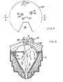
- the lid includes openings 32 and 33 for inserting primary burner 34 and auxiliary burner 35 (FIGS. 2 and 3).
- the exhaust gases escape upwardly through an opening 36 through the lid 28 and into an exhaust duct 38.
- the opening 36 may also be utilized for feeding the raw materials to the liquefaction chamber, and, as shown in FIG. 1, a feed chute 40 is provided for this purpose.
- a pivotable batch deflector 44 may be provided at the end of chute 40.
- upper and lower water seals 41 and 42 respectively are provided.
- the upper seal comprises a trough 43 affixed to the frame 30 and a flange 45 attached to the drum 12 and having a downwardly extending portion immersed in a liquid (e.g., water) contained in the trough 43.
- the lower seal similarly includes a trough 75 and flange 76 immersed in liquid 77.
- continuous feeding of batch to the melter 10 results in a falling stream of batch that becomes distributed over the surface of the stable batch layer 50, and by the action of the heat, e.g., from the primary burner 34 and the auxiliary burner 35, becomes liquefied in a transient layer 54 that runs to the bottom of the vessel and passes through the open center 26.
- the liquefied batch 56 falls from the exit opening and may be collected in a collection vessel 57 for further processing.
- the invention is not limited to the melting of glass batch materials.
- the invention may be advantageously practiced for control of a liquefaction process carried out with a transient layer of batch material supported by a stable layer of granular, preferably non-contaminating material.
- the preferred stable granular layer provides thermal insulation as well as a non-contaminating contact surface for the transient batch layer, and most preferably the stable layer includes one or more constituents of the batch material.
- Process parameters should be controlled to maintain desired steady state conditions within the melter, e.g., desired batch wall thickness. For this reason, the thickness of the batch wall is monitored during the melting process. It has been found that temperatures along the top of the batch wall provide a good indication of the location of the batch wall boundary within the drum 12, and further, that the boundary of the batch wall at the top of the drum is a good indication of batch wall thickness throughout the drum.
- a plurality of thermocouples may be inserted through holes 60 in the lid 28 as shown in FIG. 2.
- a centrally located thermocouple 72 is mounted in opening 73 for measuring melter temperature adjacent to the interior face 74 of the lid 28 primarily for detecting overheating of the lid and to provide a reference temperature.
- Another factor in controlling batch wall thickness is distribution of the radiant energy within the melter. More particularly, impingement of the flame issuing from burners, e.g., the burners 34 and 35, should be controlled in a manner that assures substantially uniform liquifaction of the transient layer. Localized concentration of energy could result in a zone of relatively thin batch wall, leading to localized hot spots along the drum 12 and risking overheating a portion of the drum.
- the primary burner 34 depicted in the drawings is a six port, water cooled burner for directing a flame from each port at about a 30° angle to the burner axis to produce a generally conical flame profile for providing flame impingement over a wide area of the melting surface.
- the burner is mounted slightly off center relative to the axis of symmetry of the drum 12.
- the assymmetric mounting causes the flame from each port of the primary burner to impinge upon the melting surface at varying elevations, thereby distributing the most intense zones of heating over a relatively wide area of the melting surface as the drum rotates.
- a symmetric placement of such a burner would detrimentally produce a circle of concentrated heating at a fixed elevation of the rotating batch wall.
- this type of melter it is advantageous to use a burner adapted to produce an oxygen enriched flame, and thereby utilizing intensified heat flux and relatively small exhaust gas volumes.
- the burner 35 is oriented so that the flames issuing therefrom impinge upon the transient layer adjacent to the bushing 24 primarily for controlled increase of product temperature and, as will be appreciated, for selectively increasing pressure within the melter at the outlet opening 26. If pressure control is desired primarily, the burner 35 may be directed toward the center of the opening.
- pressure close to the inner face of the lid 28, e.g., as measured through a tap 80 (shown in Figure 3), can be controlled to be, for example, slightly above ambient pressure by adjusting the exhaust draft, e.g., by means of a fan or damper within the exhaust duct 38, there can still be either positive or negative pressures at the outlet opening 26.
- Negative pressure is undesirable because it creates a tendency for ambient air to enter the melter, thereby decreasing thermal efficiency.
- ingress of ambient atmosphere dilutes the exhaust gas stream and could lead to increased formation of undesirable exhaust gas products such as oxides of nitrogen, or NO x .
- Positive pressure is also undesirable because thermal energy, exhaust gases, and loose batch dust may escape through unsealed or partially sealed openings in the melter 10, causing undesirable contamination of either the ambient atmosphere outside the melter or within a subsequent processing chamber, or erosion of refractory joints or seals in and about the melter 10. It is therefore desirable to control the pressure within the melter.
- the auxiliary burner 35 can be adjusted so that the velocity pressure of the flame issuing therefrom is sufficient to overcome a negative outlet pressure while orienting the burner to direct flames to the vicinity of the opening 26.
- "Velocity pressure" is defined as the difference between the total pressure and the static pressure on an obstacle in a flow stream.
- the burner 35 may be adjusted to keep its velocity pressure low and directed so that flames impinge upon the transient layer close to the opening 26 for the sake of temperature control of the molten product.
- a significant operating parameter affecting the existence of either positive or negative pressure at the outlet 26 is the firing rate (and thus the melter throughput). It has been found that, as throughput is increased, the outlet pressure tends to become more positive, and as throughput is decreased, it tends toward negative pressure. Therefore, overall process control involves adjustments to the burners 34 and 35 when throughput changes are made.
- melter pressures including pressure upstream of the melter (e.g., within the exhaust ducts 38 and the feed chute 40) and downstream of the melter (beyond the bushing 24).
- the velocity pressure of the combustible material from the burners 34 and 35 influences the pressure within the melter.
- solid and liquid batch materials lining the melter sidewalls form an irregular, constantly changing surface on which flames issuing from the burners 34 and 35 impinge. The varying distances between burner nozzles and the irregular melting surface create localized pressure gradients.
- the type, number, and location of the burners can vary from the examples specifically described. In particular, there may be more than two burners.
- the primary combustion means could comprise a plurality of burners directed onto different portions of the melting surface.
- pressure control at the outlet opening can advantageously be transmitted to a downstream vessel, such as collection vessel 57.
- a downstream vessel such as collection vessel 57.
Landscapes
- Chemical & Material Sciences (AREA)
- Engineering & Computer Science (AREA)
- Materials Engineering (AREA)
- Organic Chemistry (AREA)
- Combustion & Propulsion (AREA)
- Vertical, Hearth, Or Arc Furnaces (AREA)
- Glass Melting And Manufacturing (AREA)
- Feeding, Discharge, Calcimining, Fusing, And Gas-Generation Devices (AREA)
- Production Of Liquid Hydrocarbon Mixture For Refining Petroleum (AREA)
- Gasification And Melting Of Waste (AREA)
- Furnace Details (AREA)
- Application Of Or Painting With Fluid Materials (AREA)
Priority Applications (1)
| Application Number | Priority Date | Filing Date | Title |
|---|---|---|---|
| AT84114057T ATE38024T1 (de) | 1983-11-25 | 1984-11-21 | Verfahren und vorrichtung zum regeln eines schmelzvorganges durch oberflaechliches abschmelzen. |
Applications Claiming Priority (2)
| Application Number | Priority Date | Filing Date | Title |
|---|---|---|---|
| US06/555,256 US4521238A (en) | 1983-11-25 | 1983-11-25 | Method and apparatus for controlling an ablation liquefaction process |
| US555256 | 2006-10-31 |
Publications (3)
| Publication Number | Publication Date |
|---|---|
| EP0143427A2 true EP0143427A2 (fr) | 1985-06-05 |
| EP0143427A3 EP0143427A3 (en) | 1985-07-03 |
| EP0143427B1 EP0143427B1 (fr) | 1988-10-19 |
Family
ID=24216587
Family Applications (1)
| Application Number | Title | Priority Date | Filing Date |
|---|---|---|---|
| EP84114057A Expired EP0143427B1 (fr) | 1983-11-25 | 1984-11-21 | Procédé et appareil pour le contrôle d'un système de liquéfaction par ablation |
Country Status (7)
| Country | Link |
|---|---|
| US (1) | US4521238A (fr) |
| EP (1) | EP0143427B1 (fr) |
| JP (1) | JPS60186421A (fr) |
| AT (1) | ATE38024T1 (fr) |
| CA (1) | CA1234492A (fr) |
| DE (1) | DE3474655D1 (fr) |
| ES (1) | ES8603361A1 (fr) |
Cited By (2)
| Publication number | Priority date | Publication date | Assignee | Title |
|---|---|---|---|---|
| EP0312044A1 (fr) * | 1987-10-15 | 1989-04-19 | Rockwool International A/S | Procédé et four de préparation d'une masse en fusion pour la production de laine minérale |
| EP0426082A1 (fr) * | 1989-10-30 | 1991-05-08 | Praxair Technology, Inc. | Procédé de fusion de verre à production de NOX réduite |
Families Citing this family (6)
| Publication number | Priority date | Publication date | Assignee | Title |
|---|---|---|---|---|
| US4654068A (en) * | 1981-07-30 | 1987-03-31 | Ppg Industries, Inc. | Apparatus and method for ablating liquefaction of materials |
| US4610711A (en) * | 1984-10-01 | 1986-09-09 | Ppg Industries, Inc. | Method and apparatus for inductively heating molten glass or the like |
| US4678491A (en) * | 1985-11-18 | 1987-07-07 | Ppg Industries, Inc. | Reduction of material buildup by means of gas jet |
| US4738702A (en) * | 1986-10-06 | 1988-04-19 | Ppg Industries, Inc. | Glass melting in a rotary melter |
| US4780121A (en) * | 1987-04-03 | 1988-10-25 | Ppg Industries, Inc. | Method for rapid induction heating of molten glass or the like |
| US6237369B1 (en) | 1997-12-17 | 2001-05-29 | Owens Corning Fiberglas Technology, Inc. | Roof-mounted oxygen-fuel burner for a glass melting furnace and process of using the oxygen-fuel burner |
Family Cites Families (5)
| Publication number | Priority date | Publication date | Assignee | Title |
|---|---|---|---|---|
| US2006947A (en) * | 1930-06-14 | 1935-07-02 | Ferguson John | Centrifugal glass-melting furnace |
| US2834157A (en) * | 1954-11-03 | 1958-05-13 | Owens Illinois Glass Co | Glass melting furnace |
| US3917479A (en) * | 1971-12-03 | 1975-11-04 | Nat Res Dev | Furnaces |
| JPS5142434A (fr) * | 1974-10-08 | 1976-04-10 | Omron Tateisi Electronics Co | |
| US4381934A (en) * | 1981-07-30 | 1983-05-03 | Ppg Industries, Inc. | Glass batch liquefaction |
-
1983
- 1983-11-25 US US06/555,256 patent/US4521238A/en not_active Expired - Lifetime
-
1984
- 1984-11-21 EP EP84114057A patent/EP0143427B1/fr not_active Expired
- 1984-11-21 AT AT84114057T patent/ATE38024T1/de not_active IP Right Cessation
- 1984-11-21 DE DE8484114057T patent/DE3474655D1/de not_active Expired
- 1984-11-23 ES ES537896A patent/ES8603361A1/es not_active Expired
- 1984-11-23 CA CA000468550A patent/CA1234492A/fr not_active Expired
- 1984-11-24 JP JP59248573A patent/JPS60186421A/ja active Granted
Cited By (2)
| Publication number | Priority date | Publication date | Assignee | Title |
|---|---|---|---|---|
| EP0312044A1 (fr) * | 1987-10-15 | 1989-04-19 | Rockwool International A/S | Procédé et four de préparation d'une masse en fusion pour la production de laine minérale |
| EP0426082A1 (fr) * | 1989-10-30 | 1991-05-08 | Praxair Technology, Inc. | Procédé de fusion de verre à production de NOX réduite |
Also Published As
| Publication number | Publication date |
|---|---|
| ES537896A0 (es) | 1985-12-16 |
| EP0143427A3 (en) | 1985-07-03 |
| CA1234492A (fr) | 1988-03-29 |
| DE3474655D1 (en) | 1988-11-24 |
| ES8603361A1 (es) | 1985-12-16 |
| ATE38024T1 (de) | 1988-11-15 |
| JPH0427173B2 (fr) | 1992-05-11 |
| JPS60186421A (ja) | 1985-09-21 |
| EP0143427B1 (fr) | 1988-10-19 |
| US4521238A (en) | 1985-06-04 |
Similar Documents
| Publication | Publication Date | Title |
|---|---|---|
| US4473388A (en) | Process for melting glass | |
| EP0508139B1 (fr) | Four de fusion de verre avec un brûleur auxiliaire à combustion d'oxygène et à puissance élevée monté dans la paroi avale | |
| US2593197A (en) | Inclined melter furnace and method of melting glass | |
| US2834157A (en) | Glass melting furnace | |
| US4529428A (en) | Method and apparatus for feeding an ablation liquefaction process | |
| US4545798A (en) | Ablating liquefaction employing plasma | |
| NZ200542A (en) | Liquefying glass batch on sloping surface | |
| US4911637A (en) | Flame treatment method and apparatus | |
| JPH02199028A (ja) | 材料の溶融方法および装置 | |
| US4521238A (en) | Method and apparatus for controlling an ablation liquefaction process | |
| US4294603A (en) | Glass forehearth construction | |
| US4654068A (en) | Apparatus and method for ablating liquefaction of materials | |
| CA1224923A (fr) | Calcination et liquefaction d'une charge de fabrication du verre | |
| EP0132654B1 (fr) | Procédé et appareil pour la fusion d'une composition en deux étapes | |
| US4496387A (en) | Transition between batch preheating and liquefying stages apparatus | |
| US4492594A (en) | Method and apparatus for liquefying material with retainer means | |
| US4678491A (en) | Reduction of material buildup by means of gas jet | |
| USRE32317E (en) | Glass batch liquefaction | |
| US4675041A (en) | Method and apparatus for furnace lid purging | |
| US4604121A (en) | Method of pretreating glass batch | |
| CA1276789C (fr) | Appareil de chauffage | |
| US4789390A (en) | Batch melting vessel lid cooling construction | |
| US4559071A (en) | Ablating liquefaction method | |
| US4521235A (en) | Method and apparatus for controlling wall layer thickness in a liquefaction process | |
| JPH02297B2 (fr) |
Legal Events
| Date | Code | Title | Description |
|---|---|---|---|
| PUAI | Public reference made under article 153(3) epc to a published international application that has entered the european phase |
Free format text: ORIGINAL CODE: 0009012 |
|
| PUAL | Search report despatched |
Free format text: ORIGINAL CODE: 0009013 |
|
| AK | Designated contracting states |
Designated state(s): AT BE CH DE FR GB IT LI LU NL SE |
|
| AK | Designated contracting states |
Designated state(s): AT BE CH DE FR GB IT LI LU NL SE |
|
| 17P | Request for examination filed |
Effective date: 19851017 |
|
| 17Q | First examination report despatched |
Effective date: 19860930 |
|
| D17Q | First examination report despatched (deleted) | ||
| GRAA | (expected) grant |
Free format text: ORIGINAL CODE: 0009210 |
|
| AK | Designated contracting states |
Kind code of ref document: B1 Designated state(s): AT BE CH DE FR GB IT LI LU NL SE |
|
| REF | Corresponds to: |
Ref document number: 38024 Country of ref document: AT Date of ref document: 19881115 Kind code of ref document: T |
|
| REF | Corresponds to: |
Ref document number: 3474655 Country of ref document: DE Date of ref document: 19881124 |
|
| ET | Fr: translation filed | ||
| ITF | It: translation for a ep patent filed | ||
| PLBE | No opposition filed within time limit |
Free format text: ORIGINAL CODE: 0009261 |
|
| STAA | Information on the status of an ep patent application or granted ep patent |
Free format text: STATUS: NO OPPOSITION FILED WITHIN TIME LIMIT |
|
| 26N | No opposition filed | ||
| PG25 | Lapsed in a contracting state [announced via postgrant information from national office to epo] |
Ref country code: LI Effective date: 19891130 Ref country code: CH Effective date: 19891130 |
|
| REG | Reference to a national code |
Ref country code: CH Ref legal event code: PL |
|
| ITTA | It: last paid annual fee | ||
| EPTA | Lu: last paid annual fee | ||
| EAL | Se: european patent in force in sweden |
Ref document number: 84114057.7 |
|
| PGFP | Annual fee paid to national office [announced via postgrant information from national office to epo] |
Ref country code: LU Payment date: 19961001 Year of fee payment: 13 |
|
| PGFP | Annual fee paid to national office [announced via postgrant information from national office to epo] |
Ref country code: FR Payment date: 19961021 Year of fee payment: 13 |
|
| PGFP | Annual fee paid to national office [announced via postgrant information from national office to epo] |
Ref country code: SE Payment date: 19961022 Year of fee payment: 13 |
|
| PGFP | Annual fee paid to national office [announced via postgrant information from national office to epo] |
Ref country code: NL Payment date: 19961024 Year of fee payment: 13 Ref country code: AT Payment date: 19961024 Year of fee payment: 13 |
|
| PGFP | Annual fee paid to national office [announced via postgrant information from national office to epo] |
Ref country code: GB Payment date: 19961025 Year of fee payment: 13 |
|
| PGFP | Annual fee paid to national office [announced via postgrant information from national office to epo] |
Ref country code: DE Payment date: 19961028 Year of fee payment: 13 |
|
| PGFP | Annual fee paid to national office [announced via postgrant information from national office to epo] |
Ref country code: BE Payment date: 19961029 Year of fee payment: 13 |
|
| PG25 | Lapsed in a contracting state [announced via postgrant information from national office to epo] |
Ref country code: LU Free format text: LAPSE BECAUSE OF NON-PAYMENT OF DUE FEES Effective date: 19971121 Ref country code: GB Free format text: LAPSE BECAUSE OF NON-PAYMENT OF DUE FEES Effective date: 19971121 Ref country code: AT Free format text: LAPSE BECAUSE OF NON-PAYMENT OF DUE FEES Effective date: 19971121 |
|
| PG25 | Lapsed in a contracting state [announced via postgrant information from national office to epo] |
Ref country code: SE Free format text: LAPSE BECAUSE OF NON-PAYMENT OF DUE FEES Effective date: 19971122 |
|
| PG25 | Lapsed in a contracting state [announced via postgrant information from national office to epo] |
Ref country code: FR Free format text: THE PATENT HAS BEEN ANNULLED BY A DECISION OF A NATIONAL AUTHORITY Effective date: 19971130 Ref country code: BE Free format text: LAPSE BECAUSE OF NON-PAYMENT OF DUE FEES Effective date: 19971130 |
|
| BERE | Be: lapsed |
Owner name: PPG INDUSTRIES INC. Effective date: 19971130 |
|
| PG25 | Lapsed in a contracting state [announced via postgrant information from national office to epo] |
Ref country code: NL Free format text: LAPSE BECAUSE OF NON-PAYMENT OF DUE FEES Effective date: 19980601 |
|
| GBPC | Gb: european patent ceased through non-payment of renewal fee |
Effective date: 19971121 |
|
| PG25 | Lapsed in a contracting state [announced via postgrant information from national office to epo] |
Ref country code: DE Free format text: LAPSE BECAUSE OF NON-PAYMENT OF DUE FEES Effective date: 19980801 |
|
| EUG | Se: european patent has lapsed |
Ref document number: 84114057.7 |
|
| NLV4 | Nl: lapsed or anulled due to non-payment of the annual fee |
Effective date: 19980601 |
|
| REG | Reference to a national code |
Ref country code: FR Ref legal event code: ST |