EP0143443A2 - Appareil à tête pour disque magnétique - Google Patents
Appareil à tête pour disque magnétique Download PDFInfo
- Publication number
- EP0143443A2 EP0143443A2 EP84114152A EP84114152A EP0143443A2 EP 0143443 A2 EP0143443 A2 EP 0143443A2 EP 84114152 A EP84114152 A EP 84114152A EP 84114152 A EP84114152 A EP 84114152A EP 0143443 A2 EP0143443 A2 EP 0143443A2
- Authority
- EP
- European Patent Office
- Prior art keywords
- arm
- carriage
- pin
- supporting member
- magnetic
- Prior art date
- Legal status (The legal status is an assumption and is not a legal conclusion. Google has not performed a legal analysis and makes no representation as to the accuracy of the status listed.)
- Withdrawn
Links
Images

Classifications
-
- G—PHYSICS
- G11—INFORMATION STORAGE
- G11B—INFORMATION STORAGE BASED ON RELATIVE MOVEMENT BETWEEN RECORD CARRIER AND TRANSDUCER
- G11B17/00—Guiding record carriers not specifically of filamentary or web form, or of supports therefor
- G11B17/02—Details
- G11B17/04—Feeding or guiding single record carrier to or from transducer unit
- G11B17/041—Feeding or guiding single record carrier to or from transducer unit specially adapted for discs contained within cartridges
-
- G—PHYSICS
- G11—INFORMATION STORAGE
- G11B—INFORMATION STORAGE BASED ON RELATIVE MOVEMENT BETWEEN RECORD CARRIER AND TRANSDUCER
- G11B5/00—Recording by magnetisation or demagnetisation of a record carrier; Reproducing by magnetic means; Record carriers therefor
- G11B5/48—Disposition or mounting of heads or head supports relative to record carriers ; arrangements of heads, e.g. for scanning the record carrier to increase the relative speed
- G11B5/54—Disposition or mounting of heads or head supports relative to record carriers ; arrangements of heads, e.g. for scanning the record carrier to increase the relative speed with provision for moving the head into or out of its operative position or across tracks
Definitions
- the present invention relates to magnetic disk head apparatus, and is applicable to a head arm supporting and opening mechanism in a double-side type magnetic disk device which magnetically records signals on both sides of a flexible magnetic disk.
- the invention is applicable, inter alia, to an opening mechanism which will accommodate a hard case disk.
- a conventional head arm supporting mechanism in a double- sided type magnetic disk device is shown in Fig. 1.
- a flexible disk 1 spins between a first magnetic head 2 and a second magnetic head 3.
- a carriage 4 holds the second magnetic head 3 while an arm 5 holds the first magnetic head 2.
- the arm 5 is held by a leaf spring 6 secured to the carriage 4 , the leaf spring 6 providing a fulcrum point for swinging the arm 5.
- a bracket 7 and screw 9 secure the leaf spring 6 to the carriage 4 and determines the fulcrum and bending force for the arm 5.
- An arm pressurizing spring 8 exerts a closing force on the arm 5.
- a lift member 5a is provided on the arm 5 and is connected to an arm operating plate 10 held on a bridge integral with a door handle (not shown) which is moved when the flexible disk is inserted.
- the first magnetic head 2 When the flexible disk 1, in a flexible, thin, protective jacket 11, is inserted into the device to a position where it can be subjected to writing or reading, the first magnetic head 2 is lifted as shown in Fig. 2 to prevent interference with the disk 11 as it is being inserted.
- the arm operating plate 10 raises the lift member 5a provided on the arm 5 so that the arm 5 is swung about the fulcrum provided by the secured end of the leaf spring 6.
- the head arm supporting mechanism of Fig. 1 is sufficient.
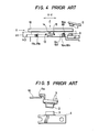
- the magnetic disk device is structured as illustrated by Fig. 4.
- Positioning pins 14 and 15 on spindle 13 are used to position the flexible disk 1 and to transmit rotation to the disk 1.
- Protrusions 16c and 16d on hard case positioning pins 16a and 16b are used to position the hard case in the X and Y directions. Steps 17a and 17b and steps 16e and 16f position the hard case in the Z direction.
- the hard case 12 has positioning pin holes 18, 19, 20 and 21, respectively, for the above-described positioning pins, as illustrated in Fig. 3.
- the hard case 12 When the hard case 12 is inserted into the device, it is necessary to move the hard case 12 vertically to position it at the reading and writing position. During insertion, the hard case 12 is held at an insertion level HI (Fig. 4) by a guide (not shown), and is then moved in the direction of the arrow Y to a predetermined position. The hard case 12, together with the guide, is then moved in the direction of the arrow Z and positioned at an operating level H 2 resting against steps 17a, 17b, 16e and 16f:
- the first magnetic head 2 When the hard case is moved as described above, the first magnetic head 2 should have an opening stroke or distance of t + (H i - H 2 ), where t is the thickness of the hard case 12. To . prevent interference between the first magnetic head 2 and the hard case 12, the opening stroke of the first magnetic head 2 is necessarily larger than the stroke necessary for a flexible case disk 1.
- the conventional arm supporting system when applied to the hard case 12 suffers from several problems.
- the leaf spring 6 provides the fulcrum for arm swing and if the opening distance of the arm 5 is increased, it is difficult to keep the mechanical strength of the leaf spring from. changing due to the stress applied to the fulcrum when the arm 5 is repeatedly opened and closed. This fulcrum limitation thereby limits the opening stroke of the arm.
- the leaf spring 6 can be designed by utilizing the general formula for a cantilever in accordance with the equation (1): where D is the leaf spring's defection, L is the length of the leaf spring 6, H is the thickness of the leaf spring 6, A is the stress on the leaf spring 6, and E is the elastic modulus.
- equation 1 indicates that either the length L of the leaf spring 6 should be increased or the thickness H should be decreased.
- the thickness of the spring in the conventional device is generally as small as O.lt and if the thickness is further decreased, the reliability of the device is reduced and it becomes difficult to operate.
- the leaf spring 6 can be twisted which results in the first magnetic head being permanently angled as indicated by the solid lines in Fig. 5.
- the first magnetic head 2 cannot be satisfactorily opened and interference between the hard case 12 and the first magnetic head 2 can occur.
- the angling of the head 2 due to a twisting moment occurs because of the difference in position between the lift member 5a of the arm 5 and the arm pressurizing spring 8. This problem may be eliminated by changing the position of the arm pressurizing spring 8 to the position of the lift member 5a.
- a head arm supporting mechanism in a magnetic disk device in which the arm has a pin as its fulcrum.
- the pin is supported by supporting members each having a V-shaped groove, so that the supporting members are increased in rigidity and, as a result, the operating efficiency is also increased.
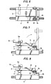
- the pin 21 provides the fulcrum.
- the pin 21 is also supported by the V-shaped grooved members 23 and urged in one direction by the spring 24.
- the opening stroke of the arm 5 is determined from the limit on stress that can be placed on the leaf spring 6.
- the fulcrum of swing for the arm 5 is provided by the pin supporting structure 23 and, therefore, the arm can have a sufficient opening stroke to prevent interference of the first magnetic head 2 with the hard case 12.
- the opening stroke of the arm 5 is not substantialy limited; that is, the arm can be swung at least 90° as indicated in the one-dot chain lines in Fig. 7.
- the disk device according to the present invention is designed to eliminate the drawbacks accompanying the conventional device that result in difficulty in maintenance due to difficulty in observing the contact surface of the first magnetic head 2.
- the leaf spring 6 of the arm 5 is twisted by the moment produced by the difference between the position of the lift member 5a and the arm pressurizing position.
- the stroke of the lift member is shorter than that of the first magnetic head 2.
- the rotation fulcrum pin 21 is integral with the arm 5 and is sufficiently rigid with respect to the twisting force at the fulcrum to avoid twisting.
- the stroke of the lift member 5a and the first magnetic head 2 can be substantially equal to each other and the reduction in the available stroke of the first magnetic head 2 in the conventional device can be eliminated.
- the rotation fulcrum pin 21 is supported by the V-shaped groove members 23 and the relative position of the carriage 4 and the arm 5 can be determined merely by placing the rotation fulcrum pin 21 of the arm 5 on the sloped sidewalls of the V-shaped groove members 23, which contributes to
- the leaf springs 24 are used to indirectly support the rotation fulcrum pin 21; that is, the leaf springs 24 depress the pin 21 against the sloped sidewalls of the V-shaped groove members 23. Displacement of the head 2 radially with respect to the flexible disk 1 (in the Y-Y direction of Fig. 4) (that is, a head alignment error factor which must be taken seriously in designing the magnetic disk device and which causes a displacement of the first and second magnetic heads relative to each other)will not occur in the device according to the present invention.
- the displacment error will not occur to a significant extent even if the sloped sidewalls of the V-shaped grooves are worn out over time by rotation of the rotation fulcrum pin 21 because the latter is stably positioned due to leaf springs 24 pushing the pin 21 against the sloped sidewalls.
- the V-shaped groove members 23 are integral with the carriage 4.
- the embodiment may be modified so that supporting members 26 including V-shaped groove members 23 are provided separately from the carriage 4, as illustrated in Fig. 8, ' and the groove members can be secured to the carriage 4 with screws 25.
- the first magnetic head 2 can then be adjusted independently of the second magnetic head 3 by loosening the screws 25.
- the alignment accuracy of the components can be increased because mechanical errors can be removed by adjusting the position of the supporting member 26.
- a head arm supporting mechanism in which the relative position of the magnetic heads can be maintained with high accuracy can be provided at a lower manufacturing cost.
- the present invention can also be effectively applied to magnetic disk device using a flexible jacket.
Landscapes
- Supporting Of Heads In Record-Carrier Devices (AREA)
- Moving Of Heads (AREA)
Applications Claiming Priority (2)
| Application Number | Priority Date | Filing Date | Title |
|---|---|---|---|
| JP58221141A JPS60113360A (ja) | 1983-11-24 | 1983-11-24 | 磁気デイスク装置 |
| JP221141/83 | 1983-11-24 |
Publications (2)
| Publication Number | Publication Date |
|---|---|
| EP0143443A2 true EP0143443A2 (fr) | 1985-06-05 |
| EP0143443A3 EP0143443A3 (fr) | 1986-09-17 |
Family
ID=16762103
Family Applications (1)
| Application Number | Title | Priority Date | Filing Date |
|---|---|---|---|
| EP84114152A Withdrawn EP0143443A3 (fr) | 1983-11-24 | 1984-11-23 | Appareil à tête pour disque magnétique |
Country Status (4)
| Country | Link |
|---|---|
| US (1) | US4716479A (fr) |
| EP (1) | EP0143443A3 (fr) |
| JP (1) | JPS60113360A (fr) |
| AU (1) | AU574406B2 (fr) |
Cited By (3)
| Publication number | Priority date | Publication date | Assignee | Title |
|---|---|---|---|---|
| DE3605132A1 (de) * | 1985-06-11 | 1986-12-11 | Mitsubishi Denki K.K., Tokio/Tokyo | Stuetzvorrichtung zum unterstuetzen eines tastkopfes einer diskettenvorrichtung |
| DE8814519U1 (de) * | 1988-11-22 | 1989-04-13 | Marek, Alois, Dipl.-Ing., 5400 Koblenz | Oberer Schreiblesekopf des 5 1/4" Floppy Diskettenlaufwerkes |
| US8567953B2 (en) | 2005-04-26 | 2013-10-29 | Imax Corporation | Systems and methods for projecting composite images |
Families Citing this family (2)
| Publication number | Priority date | Publication date | Assignee | Title |
|---|---|---|---|---|
| TW209901B (fr) * | 1992-01-27 | 1993-07-21 | Sony Co Ltd | |
| US7933191B2 (en) * | 2006-10-27 | 2011-04-26 | Van Brocklin Andrew L | Optical disc drive having two optomechanical mechanisms |
Family Cites Families (8)
| Publication number | Priority date | Publication date | Assignee | Title |
|---|---|---|---|---|
| US3219988A (en) * | 1961-02-01 | 1965-11-23 | Bunker Ramo | Magnetic recording device |
| US4133015A (en) * | 1977-03-16 | 1979-01-02 | Sycor, Inc. | Head positioner for disc recorders |
| US4250530A (en) * | 1979-10-05 | 1981-02-10 | Yang Electromagnetic Systems Inc. | Fixed and movable supporting of dual magnetic heads |
| IT1128485B (it) * | 1980-07-14 | 1986-05-28 | Olivetti & Co Spa | Dispositivo per registrare e o leggere informazioni binarie su entrambe le facce di un disco magnetico flessibile |
| JPS5766572A (en) * | 1980-10-09 | 1982-04-22 | Mitsubishi Electric Corp | Magnetic head moving device of both-sided flexible disk storage device |
| US4376294A (en) * | 1981-11-16 | 1983-03-08 | Dma Systems Corporation | Head loading and retraction apparatus for magnetic disc storage systems |
| US4470088A (en) * | 1982-01-08 | 1984-09-04 | Xerox Corporation | Pivot suspension for head arm on disk drive |
| CA1210500A (fr) * | 1982-02-19 | 1986-08-26 | Udo Boehm | Support de bras d'enregistrement-lecture a une ou plusieurs tetes pour enregistreut-lecteur de disque |
-
1983
- 1983-11-24 JP JP58221141A patent/JPS60113360A/ja active Pending
-
1984
- 1984-11-23 AU AU35835/84A patent/AU574406B2/en not_active Ceased
- 1984-11-23 EP EP84114152A patent/EP0143443A3/fr not_active Withdrawn
-
1987
- 1987-03-19 US US07/028,059 patent/US4716479A/en not_active Expired - Fee Related
Cited By (3)
| Publication number | Priority date | Publication date | Assignee | Title |
|---|---|---|---|---|
| DE3605132A1 (de) * | 1985-06-11 | 1986-12-11 | Mitsubishi Denki K.K., Tokio/Tokyo | Stuetzvorrichtung zum unterstuetzen eines tastkopfes einer diskettenvorrichtung |
| DE8814519U1 (de) * | 1988-11-22 | 1989-04-13 | Marek, Alois, Dipl.-Ing., 5400 Koblenz | Oberer Schreiblesekopf des 5 1/4" Floppy Diskettenlaufwerkes |
| US8567953B2 (en) | 2005-04-26 | 2013-10-29 | Imax Corporation | Systems and methods for projecting composite images |
Also Published As
| Publication number | Publication date |
|---|---|
| AU3583584A (en) | 1985-05-30 |
| US4716479A (en) | 1987-12-29 |
| EP0143443A3 (fr) | 1986-09-17 |
| JPS60113360A (ja) | 1985-06-19 |
| AU574406B2 (en) | 1988-07-07 |
Similar Documents
| Publication | Publication Date | Title |
|---|---|---|
| US6550328B1 (en) | Dynamic balance correction for a disc drive | |
| USRE37426E1 (en) | Floppy disk dive device | |
| EP0049943B1 (fr) | Assemblage de têtes magnétiques mobiles pour un dispositif de mémoire à disque flexible à double face | |
| US8336179B2 (en) | Fixture assembly | |
| GB2189927A (en) | Disk drive with spicule member | |
| EP0259952A1 (fr) | Système de support de tête magnétique pour unité de disque à deux têtes | |
| EP0381368B1 (fr) | Entrainement de disque rigide avec un axe en sécurité | |
| US4876623A (en) | Magnetic disc device with gimbal spring having variable elastic characteristics | |
| US4716479A (en) | Magnetic disk head opening mechanism with an expanded opening range | |
| US5786677A (en) | Stops and a clutch for a loader that test the flying height of a disk drive head gimbal assembly | |
| US5540542A (en) | HDA headload carriage tooling | |
| US4628385A (en) | Two stage colleting in a flexible disk drive | |
| EP0044151B1 (fr) | Appareil pour l'enregistrement et/ou la lecture d'informations binaires des deux côtés d'un disque magnétique flexible | |
| KR100195380B1 (ko) | 디스크 파지 장치 | |
| US7616408B2 (en) | Hard disk drive connecting a flexible printed circuit and actuator having vertical mating | |
| EP0084123B1 (fr) | Chariot à suspension en porte à faux pour transducteur | |
| US6057988A (en) | Adjustable head suspension load/unload lift cam assembly | |
| JPS58122674A (ja) | デイスク駆動装置におけるヘツドア−ムのためのピボツト支持構造 | |
| US20030039077A1 (en) | Tape head module assembly system and method | |
| JPH0917142A (ja) | データカートリッジ | |
| KR100263293B1 (ko) | 부품장착장치 | |
| EP0062454B1 (fr) | Assemblage de têtes magnétiques pour disques magnétiques | |
| US5023735A (en) | Magnetic head support device with double gimbal structure | |
| US4719692A (en) | Method of manufacturing a magnetic head assembly | |
| US4809427A (en) | Method for assembling a magnetic head supporting mechanism of a flexible disk drive apparatus |
Legal Events
| Date | Code | Title | Description |
|---|---|---|---|
| PUAI | Public reference made under article 153(3) epc to a published international application that has entered the european phase |
Free format text: ORIGINAL CODE: 0009012 |
|
| AK | Designated contracting states |
Designated state(s): DE FR GB |
|
| PUAL | Search report despatched |
Free format text: ORIGINAL CODE: 0009013 |
|
| AK | Designated contracting states |
Kind code of ref document: A3 Designated state(s): DE FR GB |
|
| STAA | Information on the status of an ep patent application or granted ep patent |
Free format text: STATUS: THE APPLICATION IS DEEMED TO BE WITHDRAWN |
|
| 18D | Application deemed to be withdrawn |
Effective date: 19870318 |
|
| RIN1 | Information on inventor provided before grant (corrected) |
Inventor name: KOIKE, KAZUOC/O MITSUBISHI DENKI K.K. Inventor name: SAKAMOTO, YUZOC/O MITSUBISHI DENKI K.K. |