EP0143546A1 - Appareil pour le déchargement de convoyeurs - Google Patents
Appareil pour le déchargement de convoyeurs Download PDFInfo
- Publication number
- EP0143546A1 EP0143546A1 EP84307317A EP84307317A EP0143546A1 EP 0143546 A1 EP0143546 A1 EP 0143546A1 EP 84307317 A EP84307317 A EP 84307317A EP 84307317 A EP84307317 A EP 84307317A EP 0143546 A1 EP0143546 A1 EP 0143546A1
- Authority
- EP
- European Patent Office
- Prior art keywords
- conveyor
- feed conveyor
- article
- escapement mechanism
- articles
- Prior art date
- Legal status (The legal status is an assumption and is not a legal conclusion. Google has not performed a legal analysis and makes no representation as to the accuracy of the status listed.)
- Withdrawn
Links
- 239000000872 buffer Substances 0.000 claims abstract description 8
- 230000003139 buffering effect Effects 0.000 claims description 2
- 230000001360 synchronised effect Effects 0.000 abstract 1
- 235000013305 food Nutrition 0.000 description 5
- 235000019219 chocolate Nutrition 0.000 description 4
- 238000000034 method Methods 0.000 description 3
- 230000005484 gravity Effects 0.000 description 1
- 239000000463 material Substances 0.000 description 1
- 238000012986 modification Methods 0.000 description 1
- 230000004048 modification Effects 0.000 description 1
Images


Classifications
-
- B—PERFORMING OPERATIONS; TRANSPORTING
- B65—CONVEYING; PACKING; STORING; HANDLING THIN OR FILAMENTARY MATERIAL
- B65G—TRANSPORT OR STORAGE DEVICES, e.g. CONVEYORS FOR LOADING OR TIPPING, SHOP CONVEYOR SYSTEMS OR PNEUMATIC TUBE CONVEYORS
- B65G47/00—Article or material-handling devices associated with conveyors; Methods employing such devices
- B65G47/74—Feeding, transfer, or discharging devices of particular kinds or types
- B65G47/84—Star-shaped wheels or devices having endless travelling belts or chains, the wheels or devices being equipped with article-engaging elements
- B65G47/846—Star-shaped wheels or wheels equipped with article-engaging elements
Definitions
- This invention relates generally to apparatus for unloading conveyors and finds particular but not exclusive application to the lateral offloading of similar articles moving on a conveyor on to second, eg transverse, conveyor or into receptacles moving on said second conveyor.
- the known proposals for offloading apparatus include suction devices and mechanised grippers. Suction cups are generally applicable onto smooth surfaced, non-porous items, whilst grippers are applicable only to items firm enough to withstand the grippers. In addition, this type of offloading apparatus is usually relatively slow.
- Other proposals include trap door devices, wherein the items are successively conveyed over a trap door which is then either slid back or tilted to drop the item into a tray. Apparatus of this type is also relatively slow. Furthermore, as the items often fall freely under gravity they may drop into a tilted or canted position in the tray. The use of multiple trap doors can speed up the process, but only at the cost of increased material handling and machine complexity.
- apparatus for use with a feed conveyor on which a succession of similar articles are conveyed in line with freedom for slippage in the feed direction to form a transfer station at which articles can be unloaded, comprises a rotary escapement mechanism having a plurality of abutment members which rotate in a common closed path whilst maintaining a constant orientation relative to the direction of the feed conveyor, the rotary escapement mechanism being positioned relative to the feed conveyor so that a trailing face of each abutment member buffers the foremost of the in-line articles on the feed conveyor whilst a lateral face of the following abutment member operates so as to push the buffered article laterally relative to the feed conveyor, movement of the buffering Imember in the direction of the feed conveyor permitting the buffered article to advance on the feed conveyor to the transfer station whilst being laterally displaced, the arrangement being such that, when a buffered article reaches the transfer station, it has been pushed laterally sufficiently far to leave the lateral edge of the feed conveyor so as to pass
- the invention is especially applicable, in the food industry, to the loading of articles such a cholocolate bars or other food items into receptacles such as preformed trays.
- apparatus for loading similar articles into receptacles comprising:-
- the so-called feed conveyor may be a main in-feed conveyor or a transfer conveyor for transferring articles from an in-feed conveyor to the transfer station.
- the articles are preferably delivered in line to the transfer station, guide means being provided to maintain such article alignment.
- the guide means ends at a point relative to the locus of the abutment members of the rotary escapement mechanism such that the trailing end of each abutment member co-operates with the guide means and moves in a manner relative thereto so as to laterally separate each foremost buffered article from the next following article in the line.
- the feed conveyor is preferably driven by one motor, whilst the rotary escapement mechanism and take-up conveyor are driven by another motor, the rotary escapement mechanism and take-up conveyor being geared together such that the latter moves forward one article-receiving place for that angle of rotation of the escapement mechanism necessary to buffer and offload one article.
- the feed conveyor is preferably a closed loop belt conveyor with an upper run traversing over the top of the take-up conveyor and a lower run traversing beneath the take-up conveyor.
- the latter conveyor is preferably a non-stretch timing belt with teeth interlocking with a driving pulley and projections to hold the receptacles in predetermined registration both with one another and with the off-load point at the transfer station along the feed conveyor.
- the rotary escapement mechanism is, of course, positioned at the junction of the two conveyors.
- a preferred rotary escapement mechanism comprises upper and lower discs separated in eccentric relationship by a crank at the centre and a number of corresponding outer cranks towards the periphery, the abutment members being in the form of blocks secured as by being pinned to the crankshafts of the outer cranks below the lower disc.
- This arrangement is preferably driven by holding the shaft of the centre crank rigid, above the upper disc, and driving said upper disc, for example, by a timing belt pulley.
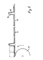
- the reference 10 denotes a feed delivery conveyor
- the reference 12 denotes a take-up conveyor operative at right angles to the feed conveyor.
- the intersection of the two conveyors defines a transfer station.
- the feed conveyor 10 feeds articles 18, such as chocolate bars or like food items, toward on offloading point in the transfer station (generally indicated 14), whereat the articles are delivered into receptacles 16 borne by the take-up conveyor 12.
- the articles 18 are similar in shape and form, and in particular being of similar length, at least approximately similar width, and of thickness sufficient to prevent them riding up on one another, as they are fed in aligned nose to tail relationship by the feed conveyor 10.
- the latter is a simple belt conveyor which, as indicated in Figure 4, has an upper run 20 passing on a dead plate above the take-up conveyor 12 and a lower run 21 passing beneath it.
- the feed conveyor is powered by an independant motor.
- the take-up conveyor 12 (see Figure 5) is a non-stretch timing belt having a lower driven side 22 with teeth which interlock with a driving pulley 24, and with projections 26 on the upper side for holding the receptacles 16, which as illustrated in Figure 1 are preformed trays each having depressions for receiving a plurality of chocolate bars or like food items.
- the invention is applicable to other situations, such as one receptacle per article on the one hand , and delivery of articles on to the take-up conveyor, without use of receptacles, on the other.
- Figure 5 shows a plain tray without depressions for receiving a plurality of articles.
- the means of offloading the articles from the feed conveyor 10 into the receptacles on the take-up conveyor is a rotary escapement mechanism, generally referenced 28, driven by the same motor as the take-up conveyor 12 through a timing belt 29 and timing pulley 30 (see Figure 2).
- the rotary escapement mechanism comprises upper and lower discs, respectively 32, 34, as shown in Figures 1 to 3, separated in eccentric relationship by a central crank 36 and six corresponding outer cranks 38. Abutment blocks 40 are pinned to the lower crankshafts of the outer cranks 38, below the lower disc.
- the upper crankshaft of the central pulley is fixed at 42, and it is the upper disc 32 which is driven by the timing belt 29 through the timing pulley 30.
- the abutment blocks 40 process in a closed generally circular path, whilst maintaining a fixed orientation relative to the line of the feed conveyor.
- abutment block 40 which acts as a buffer slowing down movement of said foremost article 18, and thus of the whole following line of articles, as permitted by slippage of the articles on the conveyor belt 10.
- Abutment block 40 forms part of the rotary escapement mechanism 28, and buffered advance of the foremost article 18 is permitted as this escapement mechanism rotates.
- the next abutment block 40 will be brought to bear laterally against the side of the buffered artical 18, so that during its buffered advance, the article is also pushed laterally towards the edge of the feed conveyor 10.
- reference 18' denotes an article which is being pushed laterally by abutment block 40. The article 18 will be correspondingly pushed by the abutment block 40'.
- Reference 42 denotes a stop, adjustable in position across the width of the take-up conveyor 12. Buffered article 18' continues its advance, as well as being laterally pushed to overlie the edge of the feed conveyor, until it comes up against the stop 42. At this point of movement of the rotary escapement mechanism or very shortly thereafter, abutment block 40', laterally pushes article 18 into a position in which it so overhangs the edge of the feed conveyor as to drop off over such edge into the receptacle 16 on the take-up conveyor. The latter conveyor subsequently advances one article-receivng place, ready to receive the article 18 laterally pushed by abutment block 40' in due course.
- Guides 44 for maintaining the in-line relationship of the articles on the feed conveyor are of considerable importance.
- such guide means ends at 46 only just short of the rotary escapement mechanism 28 and co-operates therewith to maintain the in-line orientation of the foremost article buffered by block 40 whilst the preceding article 18 is being laterally separated therefrom by the pushing action of this block 40.
Landscapes
- Engineering & Computer Science (AREA)
- Mechanical Engineering (AREA)
- Branching, Merging, And Special Transfer Between Conveyors (AREA)
- Attitude Control For Articles On Conveyors (AREA)
- Specific Conveyance Elements (AREA)
- Intermediate Stations On Conveyors (AREA)
Applications Claiming Priority (2)
| Application Number | Priority Date | Filing Date | Title |
|---|---|---|---|
| GB838329272A GB8329272D0 (en) | 1983-11-02 | 1983-11-02 | Unloading conveyors |
| GB8329272 | 1983-11-02 |
Publications (1)
| Publication Number | Publication Date |
|---|---|
| EP0143546A1 true EP0143546A1 (fr) | 1985-06-05 |
Family
ID=10551117
Family Applications (1)
| Application Number | Title | Priority Date | Filing Date |
|---|---|---|---|
| EP84307317A Withdrawn EP0143546A1 (fr) | 1983-11-02 | 1984-10-24 | Appareil pour le déchargement de convoyeurs |
Country Status (6)
| Country | Link |
|---|---|
| EP (1) | EP0143546A1 (fr) |
| DK (1) | DK520984A (fr) |
| ES (1) | ES537297A0 (fr) |
| GB (2) | GB8329272D0 (fr) |
| GR (1) | GR80813B (fr) |
| IE (1) | IE55786B1 (fr) |
Cited By (3)
| Publication number | Priority date | Publication date | Assignee | Title |
|---|---|---|---|---|
| DE3830401A1 (de) * | 1988-09-07 | 1990-03-15 | Ernst Dipl Ing Kiefer | Auswerfer von fehlobjekten |
| DE3844795C2 (en) * | 1988-09-07 | 1991-10-17 | Ernst Dipl.-Ing. 6943 Birkenau De Kiefer | Ejector for faulty articles on conveyor belt |
| WO1997020722A1 (fr) * | 1995-12-05 | 1997-06-12 | Rsl Logistik Gmbh & Co. | Dispositif convoyeur |
Families Citing this family (1)
| Publication number | Priority date | Publication date | Assignee | Title |
|---|---|---|---|---|
| IT1201607B (it) * | 1986-12-17 | 1989-02-02 | Gd Spa | Metodo per il trasferimento e l'ordinamento secondo un passo determinato di prodotti alimentati con ordine casuale |
Citations (1)
| Publication number | Priority date | Publication date | Assignee | Title |
|---|---|---|---|---|
| DE2735364B2 (de) * | 1977-08-05 | 1979-06-13 | Tevopharm-Schiedam B.V, Schiedam (Niederlande) | Vorrichtung zum vereinzelten Herabschieben von Gegenstanden von einem endlosen Förderer |
Family Cites Families (2)
| Publication number | Priority date | Publication date | Assignee | Title |
|---|---|---|---|---|
| CH568906A5 (fr) * | 1973-07-18 | 1975-11-14 | Sig Schweiz Industrieges | |
| DE2932431A1 (de) * | 1979-08-10 | 1981-02-26 | Rose Verpackungsmasch | Vorrichtung zum vereinzeln und zufuehren von gegenstaenden, insbesondere von bonbons, zu einer verpackungsmaschine |
-
1983
- 1983-11-02 GB GB838329272A patent/GB8329272D0/en active Pending
-
1984
- 1984-10-24 GB GB08426900A patent/GB2148830B/en not_active Expired
- 1984-10-24 EP EP84307317A patent/EP0143546A1/fr not_active Withdrawn
- 1984-10-31 ES ES537297A patent/ES537297A0/es active Granted
- 1984-10-31 GR GR80813A patent/GR80813B/el unknown
- 1984-11-01 IE IE281184A patent/IE55786B1/en unknown
- 1984-11-01 DK DK520984A patent/DK520984A/da not_active Application Discontinuation
Patent Citations (1)
| Publication number | Priority date | Publication date | Assignee | Title |
|---|---|---|---|---|
| DE2735364B2 (de) * | 1977-08-05 | 1979-06-13 | Tevopharm-Schiedam B.V, Schiedam (Niederlande) | Vorrichtung zum vereinzelten Herabschieben von Gegenstanden von einem endlosen Förderer |
Cited By (4)
| Publication number | Priority date | Publication date | Assignee | Title |
|---|---|---|---|---|
| DE3830401A1 (de) * | 1988-09-07 | 1990-03-15 | Ernst Dipl Ing Kiefer | Auswerfer von fehlobjekten |
| DE3844795C2 (en) * | 1988-09-07 | 1991-10-17 | Ernst Dipl.-Ing. 6943 Birkenau De Kiefer | Ejector for faulty articles on conveyor belt |
| WO1997020722A1 (fr) * | 1995-12-05 | 1997-06-12 | Rsl Logistik Gmbh & Co. | Dispositif convoyeur |
| US6152285A (en) * | 1995-12-05 | 2000-11-28 | Wf Logistik Gmbh | Conveyor arrangement |
Also Published As
| Publication number | Publication date |
|---|---|
| GB2148830B (en) | 1986-11-26 |
| ES8601787A1 (es) | 1985-11-16 |
| GB2148830A (en) | 1985-06-05 |
| DK520984D0 (da) | 1984-11-01 |
| IE842811L (en) | 1985-05-02 |
| GR80813B (en) | 1985-03-01 |
| GB8329272D0 (en) | 1983-12-07 |
| IE55786B1 (en) | 1991-01-16 |
| ES537297A0 (es) | 1985-11-16 |
| GB8426900D0 (en) | 1984-11-28 |
| DK520984A (da) | 1985-05-03 |
Similar Documents
| Publication | Publication Date | Title |
|---|---|---|
| EP2969865B1 (fr) | Machine de transport de paquets et procédé correspondant | |
| US6543989B1 (en) | Lowering arms stacking apparatus | |
| US5310043A (en) | Feed apparatus with two feedscrews | |
| US6726001B2 (en) | Transfer apparatus and method for film bags | |
| US6217274B1 (en) | Continuous flow transfer system | |
| US4569620A (en) | Book turn-around and stack accumulator apparatus | |
| KR100254009B1 (ko) | 플립-슬라이드 장치 | |
| US5363950A (en) | Lumber organizer | |
| JPH11503096A (ja) | 多数個パックの包装装置 | |
| EP0734950A1 (fr) | Procédé et dispositif pour transporter du pain | |
| EP0711719A1 (fr) | Méthode pour transférer à distances égales des produits et liquide de transport à cet effet | |
| NL8900584A (nl) | Werkwijze en inrichting voor het tijdelijk stilzetten van een over omkeerwielen geleide, aangedreven transporteur met houders. | |
| DK163045B (da) | Maskine og fremgangsmaade til pakning af foedevarer | |
| NL1006715C2 (nl) | Productoverdraaginrichting alsmede een samenstel omvattende een dergelijke productoverdraaginrichting. | |
| EP0143546A1 (fr) | Appareil pour le déchargement de convoyeurs | |
| US6409007B1 (en) | Mechanism for automatically directing and dispensing parts | |
| EP0413997B1 (fr) | Dispositif pour l'alimentation de produits d'une unité d'approvisionnement vers une unité de réception | |
| JPH04500494A (ja) | 平らな対象物、更に詳しくは平袋を搬送し積荷する方法、並びにこの方法を実施する装置 | |
| US3427779A (en) | Apparatus for packaging articles | |
| NL2022601B1 (nl) | Toevoerinrichting voor het vormen van productgroepen welke gevormd zijn uit een veelheid vlakke baksels, en naar een verpakkingsmachine toevoeren de productgroepen. | |
| GB2193073A (en) | Coating apparatus | |
| US4925006A (en) | Conveyor apparatus having means for a shock-free article acceleration | |
| JP3901730B2 (ja) | 物品選択・送り出し方法及び装置 | |
| US5810150A (en) | Collator for a food product packaging machine, and method of use thereof | |
| US3631652A (en) | Counter loader packaging machine |
Legal Events
| Date | Code | Title | Description |
|---|---|---|---|
| PUAI | Public reference made under article 153(3) epc to a published international application that has entered the european phase |
Free format text: ORIGINAL CODE: 0009012 |
|
| AK | Designated contracting states |
Designated state(s): AT BE CH DE FR GB IT LI LU NL SE |
|
| 17P | Request for examination filed |
Effective date: 19851030 |
|
| 17Q | First examination report despatched |
Effective date: 19860411 |
|
| STAA | Information on the status of an ep patent application or granted ep patent |
Free format text: STATUS: THE APPLICATION IS DEEMED TO BE WITHDRAWN |
|
| 18D | Application deemed to be withdrawn |
Effective date: 19860821 |
|
| RIN1 | Information on inventor provided before grant (corrected) |
Inventor name: TULLOCH, THOMSON ROBERT |