EP0143594B1 - Ensemble miroir - Google Patents
Ensemble miroir Download PDFInfo
- Publication number
- EP0143594B1 EP0143594B1 EP84308032A EP84308032A EP0143594B1 EP 0143594 B1 EP0143594 B1 EP 0143594B1 EP 84308032 A EP84308032 A EP 84308032A EP 84308032 A EP84308032 A EP 84308032A EP 0143594 B1 EP0143594 B1 EP 0143594B1
- Authority
- EP
- European Patent Office
- Prior art keywords
- mirror
- cover
- visor
- frame
- housing
- Prior art date
- Legal status (The legal status is an assumption and is not a legal conclusion. Google has not performed a legal analysis and makes no representation as to the accuracy of the status listed.)
- Expired
Links
- 230000008878 coupling Effects 0.000 claims description 4
- 238000010168 coupling process Methods 0.000 claims description 4
- 238000005859 coupling reaction Methods 0.000 claims description 4
- 239000000463 material Substances 0.000 description 14
- 239000004744 fabric Substances 0.000 description 12
- 241001417494 Sciaenidae Species 0.000 description 8
- 238000010276 construction Methods 0.000 description 6
- 230000000712 assembly Effects 0.000 description 4
- 238000000429 assembly Methods 0.000 description 4
- 230000001681 protective effect Effects 0.000 description 4
- 239000000853 adhesive Substances 0.000 description 3
- 230000001070 adhesive effect Effects 0.000 description 3
- 238000005286 illumination Methods 0.000 description 3
- 239000004033 plastic Substances 0.000 description 2
- 229920003023 plastic Polymers 0.000 description 2
- 239000004743 Polypropylene Substances 0.000 description 1
- 230000003213 activating effect Effects 0.000 description 1
- 230000000903 blocking effect Effects 0.000 description 1
- 230000003292 diminished effect Effects 0.000 description 1
- 230000001815 facial effect Effects 0.000 description 1
- 239000004417 polycarbonate Substances 0.000 description 1
- 229920000515 polycarbonate Polymers 0.000 description 1
- -1 polypropylene Polymers 0.000 description 1
- 229920001155 polypropylene Polymers 0.000 description 1
- 239000004800 polyvinyl chloride Substances 0.000 description 1
- 229920000915 polyvinyl chloride Polymers 0.000 description 1
- 238000003466 welding Methods 0.000 description 1
- 238000004804 winding Methods 0.000 description 1
- 239000002023 wood Substances 0.000 description 1
Images

Classifications
-
- B—PERFORMING OPERATIONS; TRANSPORTING
- B60—VEHICLES IN GENERAL
- B60J—WINDOWS, WINDSCREENS, NON-FIXED ROOFS, DOORS, OR SIMILAR DEVICES FOR VEHICLES; REMOVABLE EXTERNAL PROTECTIVE COVERINGS SPECIALLY ADAPTED FOR VEHICLES
- B60J3/00—Antiglare equipment associated with windows or windscreens; Sun visors for vehicles
- B60J3/02—Antiglare equipment associated with windows or windscreens; Sun visors for vehicles adjustable in position
- B60J3/0204—Sun visors
- B60J3/0278—Sun visors structure of the body
- B60J3/0282—Sun visors structure of the body specially adapted for a courtesy mirror
Definitions
- the present invention relates to a mirror assembly particularly to a mirror assembly covered by a flexible cover and to such an assembly mounted in an automotive visor.
- Vanity mirrors for use in vehicles and particularly mounted in the visors of vehicles have become standard equipment on many cars and popular options on others.
- the mirror is covered when not in use to provide a protective cover for safety as well as covering the reflective surface which can be distracting to the driver of the vehicle.
- U.S.-A-4,227,242 describes an illuminated vanity mirror with a cover which pivots from the plane of the visor to selectively expose the mirror for use and provide a protective cover for the mirror when not in use.
- FR-A-2,429,685 described a visor having a mirror mounted therein which includes one or more sliding doors for providing a protective covering for the mirror. With such a sliding cover, the size of the mirror is greatly diminished since the rigid door must be stored in the same plane as the mirror and occupies a significant area of the visor.
- US-A-3542455 discloses a device according to the pre-characterising features of claim 1.
- a visor with a mirror assembly is characterised in that the elongate guide members comprise spaced rod means mounted to the frame, the assembly including edge members extending along opposite edges of the cover and stringing means extending over the rod means and coupling the rigid edge members to transfer tension forces from one edge member to the other for moving the flexible cover to selectively expose the mirror.
- the present invention includes stringing means extending over the rod means and coupling the rigid edge members to transfer tension forces from one edge member to the other for moving the flexible cover to selectively expose the mirror. This has the advantage that it ensures positive travel of the cover between open and closed postions.
- the combination of rigid edge members extending along opposite edges of the cover and stringing means enables the cover to be smaller than that of the prior art. It also allows easier removal of the cover.
- the frame defines a housing extending adjacent the mirror, the cover being movable between a position extended from the housing and covering the mirror to a position within the housing to expose the mirror for use.
- the guide means may comprise rod means positioned within the housing for supporting the cover which wraps around the rod means when within the housing.
- the term rod means includes rollers.
- the rod means comprises a pair of spaced rods extending between sides of the frame and at the top and bottom edges of the frame and at the stringing means extending over the spaced rods.
- the rod means comprises a fixed rod and a concentric roller sleeve.
- the cover may be a fabric material or a tambour door construction.
- a mirror assembly according to the present invention may be incorporated into a visor for a vehicle.
- a preferred embodiment provides such a mirror assembly in conjunction with a visor for a vehicle, the mirror assembly conveniently in the form of a panel, being secured to the visor.
- a visor having a covered mirror comprising a visor body defining a housing, a mirror mounted to the visor body adjacent the housing, the housing comprises an aperture extending adjacent and along the mirror, a flexible cover, roller means mounted within the housing for supporting the flexible cover, and means for moving the flexible cover between a position covering the mirror and a position extending into the housing through the aperture to expose the mirror.
- the housing is enlarged and extends along a top edge of the visor body and the roller means is positioned in the enlarged portion of the housing and comprises a biased roller to which one edge of the flexible cover is attached for winding the cover onto the roller for storage within the housing.
- the flexible cover preferably comprises a handle to enable the cover to be more easily moved.
- the handle is preferably covered to an edge of the flexible cover remote from the storing position and the roller means or rod means.
- the present invention provides, at least in the preferred embodiments, a flexible cover for use in covering a mirror which occupies significantly less space than prior structures and provides an attractive and protective mirror cover particularly adapted for use with a vanity mirror mounted in a visor.
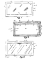
- a covered mirror panel 10 which includes a generally rectangular frame 11 having a face portion 12 through which there is formed a large rectangular opening 14 for a mirror 16.
- the frame further includes left and right sidewalls 13 and 15 extending rearwardly from the face 12 and integrally joined upper and lower rearwardly extending walls 17 and 19 to define a housing for holding the mirror 16 therein behind the opening 14.
- the mirror 16 includes a reflective surface 18 ( Figure 3) and a rear surface 20 ( Figure 2).
- the mirror 16 is secured to the frame 11 behind the opening 14 by a pair of generally vertically extending guide channels 22 and 24 secured to the inside of the face 12 of the frame.
- Each of the guide channels 22, 24 is configurated to provide a plurality of guiding and supporting functions.
- the guide channel 24 includes a vertically and rearwardly extending wall portion 25 which extends from the rear surface of the face 12 of the frame 11 spaced slightly outwardly of the aperture 14.
- the portion or segment 25 extends rearwardly a sufficient distance to provide clearance for a cover 30 and the mirror 16.
- the channel 24 then extends inwardly toward the opening 14 to define a ledge 26 against which the rear surface 20 of the mirror 16 is seated and secured by, for example, a suitable bonding material such as an adhesive.
- Each of the guide channels 22 and 24 also includes a stub section 27 extending rearwardly for the ledge 26.
- the guide channels 22 and 24 extend vertically in parallel spaced relationship to each other substantially the same distance as the height of the mirror 16 which naturally is slightly larger than the opening 14 to fill the opening when exposed.
- the mirror is selectively covered and uncovered by a flexible cover 30 which can be made of fabric such as a woven or knitted fabric typically used as the interior trim material of an automobile to thus match the cover appearance with that of the interior of the vehicle.
- the flexible cover 30 can likewise be made of flexible sheets of thin polymeric materials such as polyvinylchloride or the like or be of tambour construction with rigid wooden or plastic horizontal slats secured to a flexible fabric base.
- the lower edge of the fabric 30 is secured to a lower cover support 32 which comprises a flat, generally rectangular bar of rigid material such as polycarbonate to which the lower edge of the fabric cover 30 is secured by bonding adhesive or other conventional fastening means.
- the front centre area of the cover support 32 includes an outwardly extending handle 34 to facilitate movement of the cover between a closed position, as shown in Figure 1, to an open position, as shown in Figure 3.
- the support 32 extends, as best seen in Figure 6, adjacent the walls 25 of each of the guide channels 22 and 24 and is captively held in lateral alignment between the mirror 16 and th face 12 of the frame 11 by the guide channels which provide sufficient clearance for relatively easy motion of the support in a vertical direction between the channels 22 and 24.
- the flexible cover 30 is generally rectangular and has a length (i.e., dimension in the generally vertical direction as seen in the Figures) slightly greater than the height of the mirror so as to cover the entire height of the mirror with sufficient material to extend over an upper roller assembly 40 and downwardly behind the mirror 16 terminating in a second cover support 36, as seen in Figures 2, 4, 5 and 7.
- the support 36 extends between the stubs 27 of each of the guide channels 22 and 24, as seen in Figures 2 and 4, to be guidably supported thereby.
- the support 36 like the support 32, is a generally flat, rigid, rectangular member made of a suitable polymeric material and to which the upper edge of the flexible cover 30 is secured by suitable fastening means such as by bonding adhesives, by ultrasonic welding or the like.
- roller assemblies 40 and 50 Extending between the sidewalls 13 and 15 of the frame 11 are a pair of upper and lower roller assemblies 40 and 50, respectively.
- Each of the roller assemblies comprise a rod 45 extending into mounting bosses 46 positioned in the inside corners of the sidewalls of the frame, as best seen in Figures 2 and 4. Apertures are formed through the mounting bosses and sidewalls 13 and 15 to receive the rods which are secured in position with respect to the frame.
- Coaxially surrounding the rods 45 are an upper sleeve 42 and a lower sleeve 52 made of a suitable material such as a polymeric material and which loosely fits over each of the rods 45 so as to rotate therearound.
- the opposite corners of the cover support 32 include apertures 31 formed therein for receiving the ends of the line segments 35 and 37 which, as best seen in Figures 5 and 7, extend downwardly from the support 32, around the sleeve 52 then upwardly and through apertures 39 in opposite ends of the support 36 and are joined to one another by tensioning means such as a tension spring 41.
- the covered mirror panel 10 is fitted within the body of a visor 60 having a moulded polymeric core including a recess for receiving the frame 11 of the assembly in a recessed fashion such that the face 12 of the frame 11 is substantially flush with the surface of the body of the visor 60.
- the visor body can be manufactured of a moulded polymeric material such as polypropylene, for example as described in US-A-4,227,241 with provision made for securing the frame 11 in place within the visor body by conventional attaching means.
- the flexible cover 30 can be a fabric which conforms to a fabric covering 61 associated with the visor body.
- the upholstery of the visor in turn is coordinated to the material of the interior of the vehicle 65 to which the visor is attached by means of a pivot arm assembly 66 which can be of a construction described (EP-A-98698 CUS Serial No. 392,534).
- a pivot arm assembly 66 which can be of a construction described (EP-A-98698 CUS Serial No. 392,534).
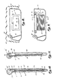
- FIG. 9 Another embodiment of the invention is illustrated in Figures 9 and 10, and in which a visor 70 includes a covered mirror panel 10 according to the present invention.
- the flexible cover 30 is of tambour door construction including a handle 34 at its lower edge for raising and lowering the door between a mirror covering position, as illustrated in Figure 9, to an open position, as illustrated in Figure 3.
- the tambour door 30 comprises a plurality of horizontally extending rigid slats 33, as seen in Figures 9 and 10, which are secured to a flexible backing material 43.
- the slats can be wood, plastics or other suitable material.
- the visor 70 includes a moulded polymeric body including a generally semi-cylindrical housing 72 at its upper end, as seen in Figure 10, for receiving, as seen in Figure 9, a pair of spaced lamp assemblies 74 and 76 each including lamp means positioned behind lenses mounted to a visor and activated by a switch 75 coupling the lamps to the vehicle's electrical supply system for projecting illumination outwardly from the assembly 74 and 76 to illuminate the area in front of the mirror 16 positioned behind the cover 30.
- the upper and lower roller assemblies 40 and 50 comprise rods 44 rotatably mounted to a pair of semi-cylindrical resilient polymeric sockets 43 integrally moulded in horizontally spaced relationship at the upper portion of the visor body and a pair of horizontally spaced lower semi-cylindrical resilient polymeric sockets 53 at the lower edge for rotatably receiving rod 51.
- the covered mirror panel 10 mounted within the visor 70 includes tension strings 35 and 37 coupled to opposite edges of the tambour door 30 to assist in the opening and closing of the door by wrapping around the upper pivot rod 44.
- the mirror 16 is mounted on a plurality of mounting pads 73 which space the mirror from the back surface 74 of the visor sufficiently to allow the tambour door to fit behind the mirror and within the relatively thin visor body.
- the visor 70 is covered by a suitable upholstery fabric 77 to conform to the upholstery fabric of the vehicle interior in which the visor is mounted.
- the visor 70 also includes a pivot mounting bracket 66 for securing the visor to a vehicle and when in the lowered use position, illustrated in Figure 9, the lights 74 and 76 can be illuminated by activating the switch 75 to provide interior illumination of the vehicle as well as for providing facial illumination for use of the vanity mirror when the cover 30 is raised using the handle 34. Since the slats 33 forming the tambour construction have some rigidity, stringing 34 and 37 can be attached directly to the tambour door without cover supports.
- a visor 80 is provided, as illustrated in Figure 1, in which the visor body includes a generally cylindrical housing 82 extending along a top edge of the body of the visor which also supports a mirror 84 selectively covered by a flexible covering material 30 with a handle 34 along its lower edge for raising and lowering the cover.
- the cover is attached to the axle 81 of a spring actuated roller such as a small window shade-type roller extending within the housing 82 and around which the cover 30 can be wound, as illustrated in phantom form in Figure 11, when the cover is moved to an open position.
- the handle 34 To open the cover, it is necessary only to press the handle 34 slightly thereby releasing the catch controlling the spring wouund roller 81 whereupon it will rotate in a clockwise direction as illustrated in Figure 11 to roll the flexible cover 30 therearound and store it within the housing 82.
- the handle 34 contacts the upper edge of the frame 11 to prevent the cover from fully retreating into the housing 82.
- the housing 82 communicates with the area in front of the mirror 84 by means of a slot 85 extending along the top edge of the mirror 84 to provide clearance therefor.
- Guide channels similar to channels 22 and 24 shown in the first embodiment are employed to provide guided support for the edges of the cover 30.
- the roller can be coupled directly to bias means such as a coil spring and tend to wind the cover around the roller, and handle 34 includes a releasable catch cooperating with the frame 11 to hold the cover in a closed position.
Landscapes
- Engineering & Computer Science (AREA)
- Mechanical Engineering (AREA)
- Passenger Equipment (AREA)
- Mirrors, Picture Frames, Photograph Stands, And Related Fastening Devices (AREA)
- Optical Elements Other Than Lenses (AREA)
- Rear-View Mirror Devices That Are Mounted On The Exterior Of The Vehicle (AREA)
Claims (5)
Applications Claiming Priority (2)
| Application Number | Priority Date | Filing Date | Title |
|---|---|---|---|
| US553645 | 1983-11-21 | ||
| US06/553,645 US4639085A (en) | 1983-11-21 | 1983-11-21 | Visor with mirror with flexible sliding cover |
Publications (2)
| Publication Number | Publication Date |
|---|---|
| EP0143594A1 EP0143594A1 (fr) | 1985-06-05 |
| EP0143594B1 true EP0143594B1 (fr) | 1987-07-08 |
Family
ID=24210190
Family Applications (1)
| Application Number | Title | Priority Date | Filing Date |
|---|---|---|---|
| EP84308032A Expired EP0143594B1 (fr) | 1983-11-21 | 1984-11-20 | Ensemble miroir |
Country Status (7)
| Country | Link |
|---|---|
| US (1) | US4639085A (fr) |
| EP (1) | EP0143594B1 (fr) |
| JP (1) | JPS60139524A (fr) |
| CA (1) | CA1240355A (fr) |
| DE (1) | DE3464561D1 (fr) |
| ES (1) | ES290201Y (fr) |
| MX (1) | MX161688A (fr) |
Cited By (1)
| Publication number | Priority date | Publication date | Assignee | Title |
|---|---|---|---|---|
| DE19545858A1 (de) * | 1995-12-08 | 1997-06-12 | Magna Zippex Autotechnik Gmbh | Sonnenblende mit Spiegelkassette für Fahrzeuge |
Families Citing this family (15)
| Publication number | Priority date | Publication date | Assignee | Title |
|---|---|---|---|---|
| US4710856A (en) * | 1986-07-07 | 1987-12-01 | Chi Kuan Manufactory Limited | Vanity mirror assembly |
| USD316392S (en) | 1988-08-15 | 1991-04-23 | Rebeck Charles C | Glare reduction shield for attachment to a vehicle mirror or similar article |
| USD315541S (en) | 1988-08-15 | 1991-03-19 | Rebeck Charles C | Glare reduction shield for attachment to a vehicle mirror or similar article |
| USD315709S (en) | 1988-08-15 | 1991-03-26 | Rebeck Charles C | Glare reduction shield for attachment to a vehicle mirror or similar article |
| US4982991A (en) * | 1989-06-29 | 1991-01-08 | United Technologies Automotive, Inc. | Upholstered sun visor |
| US5058440A (en) * | 1990-09-04 | 1991-10-22 | Caterpillar Inc. | Gas sampling device and dilution tunnel used therewith |
| US5067764A (en) * | 1990-10-26 | 1991-11-26 | Prince Corporation | Visor with extendable panel |
| US5197777A (en) * | 1990-10-26 | 1993-03-30 | Prince Corporation | Visor with extendable panel |
| ITMI20012028A1 (it) * | 2001-09-28 | 2003-03-28 | Industrialesud Spa | Dispositivo di copertura ad ingombro limitato per uno specchio di unaaletta parasole per veicoli |
| DE10200889A1 (de) * | 2002-01-11 | 2003-07-24 | Volkswagen Ag | Blendschutzeinrichtung für ein Fahrzeug, insbesondere für ein Kraftfahrzeug |
| US7534018B2 (en) * | 2007-03-16 | 2009-05-19 | International Automotive Components North America, Inc. | Illuminated visor vanity |
| US20100225248A1 (en) * | 2009-03-06 | 2010-09-09 | International Automotive Components Group North America, Inc. | Illuminated visor vanity |
| US20100296304A1 (en) * | 2009-05-19 | 2010-11-25 | Marc Hayes | Combination for a vehicle including a self-contained light |
| DE102017006487A1 (de) | 2017-07-08 | 2018-07-26 | Daimler Ag | Sonnenblende mit Spiegeleinheit |
| CN110962747B (zh) * | 2019-12-06 | 2021-03-30 | 江苏明智车业有限公司 | 一种带有保护装置的汽车后视镜 |
Family Cites Families (24)
| Publication number | Priority date | Publication date | Assignee | Title |
|---|---|---|---|---|
| US147862A (en) * | 1874-02-24 | Improvement in curtain-fixtures or rolling shutters | ||
| US146414A (en) * | 1874-01-13 | Improvement in inside blinds | ||
| US31300A (en) * | 1861-02-05 | John s | ||
| US331901A (en) * | 1885-12-08 | William mcmanes and jacob | ||
| US638314A (en) * | 1898-03-16 | 1899-12-05 | Nat Ticket Case Company | Roll-curtain. |
| US888862A (en) * | 1908-02-07 | 1908-05-26 | James G Wilson | Rolling shutter. |
| US1008748A (en) * | 1910-06-15 | 1911-11-14 | Christian Keene Snavely | Shade-roller. |
| US2003248A (en) * | 1931-08-07 | 1935-05-28 | Chilowsky Constantin | Improvements in control of glare shields of vehicles |
| US1951213A (en) * | 1932-01-25 | 1934-03-13 | Schlumbohm Peter | Color-filter-mirror |
| US2545400A (en) * | 1947-07-26 | 1951-03-13 | A E Wilson | Metal curtain |
| US2594867A (en) * | 1948-03-11 | 1952-04-29 | Carmona Juan | Rotary windshield |
| FR1096174A (fr) * | 1954-03-23 | 1955-06-09 | Dispositif filtrant combiné avec un miroir rétroviseur | |
| US2803297A (en) * | 1954-05-22 | 1957-08-20 | Wenke Helmuth Berthold Carlos | Roll shutters |
| US3375364A (en) * | 1965-10-21 | 1968-03-26 | Donnelly Mirrors Inc | Visor-mirror assembly |
| US3542455A (en) * | 1968-03-12 | 1970-11-24 | Ford Motor Co | Day-night outside rearview mirror assembly |
| GB1214108A (en) * | 1968-04-29 | 1970-12-02 | Paul Bastide | Device for controlling amount of light passing through or reflected by optical apparatus |
| JPS49110047A (fr) * | 1973-02-22 | 1974-10-19 | ||
| FR2429685A1 (fr) * | 1978-06-26 | 1980-01-25 | Maglum | Pare-soleil comportant un cache-miroir de courtoisie |
| US4213169A (en) * | 1978-11-09 | 1980-07-15 | Prince Corporation | Covered visor mirror |
| DE3045907A1 (de) * | 1980-12-05 | 1982-07-08 | Gebr. Happich Gmbh, 5600 Wuppertal | Sonnenblende, insbesondere fuer fahrzeuge |
| US4500169A (en) * | 1982-07-13 | 1985-02-19 | Donnelly John H | Cosmetic and observer line of sight mirror |
| DE3375560D1 (en) * | 1982-07-20 | 1988-03-10 | Happich Gmbh Gebr | Sun visor, especially for vehicles |
| US4486819A (en) * | 1983-10-03 | 1984-12-04 | Prince Corporation | Vehicle visor lighting apparatus |
| JPS63517A (ja) * | 1986-06-18 | 1988-01-05 | Hitachi Ltd | 水位制御方法 |
-
1983
- 1983-11-21 US US06/553,645 patent/US4639085A/en not_active Expired - Fee Related
-
1984
- 1984-11-07 CA CA000467243A patent/CA1240355A/fr not_active Expired
- 1984-11-14 MX MX203379A patent/MX161688A/es unknown
- 1984-11-19 JP JP59244333A patent/JPS60139524A/ja active Pending
- 1984-11-20 EP EP84308032A patent/EP0143594B1/fr not_active Expired
- 1984-11-20 DE DE8484308032T patent/DE3464561D1/de not_active Expired
- 1984-11-20 ES ES1984290201U patent/ES290201Y/es not_active Expired
Cited By (1)
| Publication number | Priority date | Publication date | Assignee | Title |
|---|---|---|---|---|
| DE19545858A1 (de) * | 1995-12-08 | 1997-06-12 | Magna Zippex Autotechnik Gmbh | Sonnenblende mit Spiegelkassette für Fahrzeuge |
Also Published As
| Publication number | Publication date |
|---|---|
| US4639085A (en) | 1987-01-27 |
| ES290201Y (es) | 1986-10-16 |
| CA1240355A (fr) | 1988-08-09 |
| JPS60139524A (ja) | 1985-07-24 |
| MX161688A (es) | 1990-12-13 |
| ES290201U (es) | 1986-03-16 |
| DE3464561D1 (en) | 1987-08-13 |
| EP0143594A1 (fr) | 1985-06-05 |
Similar Documents
| Publication | Publication Date | Title |
|---|---|---|
| EP0143594B1 (fr) | Ensemble miroir | |
| US4624499A (en) | Visor with pivoted concealed vanity mirror | |
| US5192110A (en) | Sunshade and vanity mirror system for a motor vehicle | |
| US7252321B2 (en) | Electric car sunshade | |
| EP0317284A1 (fr) | Paresoleil avec miroir de courtoisie à deux positions | |
| US4564234A (en) | Cover for mirror for sun visor, particularly for automobiles | |
| US4773697A (en) | Sun visor for the side windows of automotive vehicles | |
| US5374097A (en) | Universal visor mounting system | |
| US5067764A (en) | Visor with extendable panel | |
| US6692060B1 (en) | Lighted visor mirror assembly and method | |
| EP0126825A1 (fr) | Montage de pare-soleil | |
| JP2001180280A (ja) | 可撓式サンシェード装置 | |
| US6318788B1 (en) | Motorized automobile sunshade | |
| JP2001180278A (ja) | 巻取式サンシェード装置 | |
| US7121610B2 (en) | Combination shade and handle device | |
| JPS63185718U (fr) | ||
| JPH09254690A (ja) | 自動車用の遮光装置 | |
| JP4166518B2 (ja) | 自動車用サンバイザー装置 | |
| JPH0329211Y2 (fr) | ||
| CN221213431U (zh) | 一种简洁的遮阳板化妆镜总成结构 | |
| JPH0356095Y2 (fr) | ||
| JPH0742838Y2 (ja) | サンルーフパネルの通電構造 | |
| JPH0426252Y2 (fr) | ||
| EP1717077A2 (fr) | Store de protection contre le soleil électrique | |
| JPH0547687Y2 (fr) |
Legal Events
| Date | Code | Title | Description |
|---|---|---|---|
| PUAI | Public reference made under article 153(3) epc to a published international application that has entered the european phase |
Free format text: ORIGINAL CODE: 0009012 |
|
| AK | Designated contracting states |
Designated state(s): DE FR GB IT |
|
| 17P | Request for examination filed |
Effective date: 19850829 |
|
| 17Q | First examination report despatched |
Effective date: 19860324 |
|
| ITF | It: translation for a ep patent filed | ||
| GRAA | (expected) grant |
Free format text: ORIGINAL CODE: 0009210 |
|
| AK | Designated contracting states |
Kind code of ref document: B1 Designated state(s): DE FR GB IT |
|
| REF | Corresponds to: |
Ref document number: 3464561 Country of ref document: DE Date of ref document: 19870813 |
|
| ET | Fr: translation filed | ||
| PLBE | No opposition filed within time limit |
Free format text: ORIGINAL CODE: 0009261 |
|
| STAA | Information on the status of an ep patent application or granted ep patent |
Free format text: STATUS: NO OPPOSITION FILED WITHIN TIME LIMIT |
|
| 26N | No opposition filed | ||
| PGFP | Annual fee paid to national office [announced via postgrant information from national office to epo] |
Ref country code: GB Payment date: 19911017 Year of fee payment: 8 |
|
| PGFP | Annual fee paid to national office [announced via postgrant information from national office to epo] |
Ref country code: FR Payment date: 19911120 Year of fee payment: 8 |
|
| PGFP | Annual fee paid to national office [announced via postgrant information from national office to epo] |
Ref country code: DE Payment date: 19911128 Year of fee payment: 8 |
|
| ITTA | It: last paid annual fee | ||
| PG25 | Lapsed in a contracting state [announced via postgrant information from national office to epo] |
Ref country code: GB Effective date: 19921120 |
|
| GBPC | Gb: european patent ceased through non-payment of renewal fee |
Effective date: 19921120 |
|
| PG25 | Lapsed in a contracting state [announced via postgrant information from national office to epo] |
Ref country code: FR Effective date: 19930730 |
|
| PG25 | Lapsed in a contracting state [announced via postgrant information from national office to epo] |
Ref country code: DE Effective date: 19930803 |
|
| REG | Reference to a national code |
Ref country code: FR Ref legal event code: ST |