EP0143625A2 - Inactivating selector arrangement for bolt firearms - Google Patents
Inactivating selector arrangement for bolt firearms Download PDFInfo
- Publication number
- EP0143625A2 EP0143625A2 EP84308142A EP84308142A EP0143625A2 EP 0143625 A2 EP0143625 A2 EP 0143625A2 EP 84308142 A EP84308142 A EP 84308142A EP 84308142 A EP84308142 A EP 84308142A EP 0143625 A2 EP0143625 A2 EP 0143625A2
- Authority
- EP
- European Patent Office
- Prior art keywords
- trigger
- selector
- sear
- bolt
- blocking
- Prior art date
- Legal status (The legal status is an assumption and is not a legal conclusion. Google has not performed a legal analysis and makes no representation as to the accuracy of the status listed.)
- Granted
Links
Images




Classifications
-
- F—MECHANICAL ENGINEERING; LIGHTING; HEATING; WEAPONS; BLASTING
- F41—WEAPONS
- F41A—FUNCTIONAL FEATURES OR DETAILS COMMON TO BOTH SMALLARMS AND ORDNANCE, e.g. CANNONS; MOUNTINGS FOR SMALLARMS OR ORDNANCE
- F41A17/00—Safety arrangements, e.g. safeties
- F41A17/30—Multiple safeties, i.e. one safety element acting on at least one element of the firing mechanism and at least one other element of the gun, e.g. the moving barrel
- F41A17/32—Multiple safeties, i.e. one safety element acting on at least one element of the firing mechanism and at least one other element of the gun, e.g. the moving barrel the other element being the breech-block or bolt
-
- F—MECHANICAL ENGINEERING; LIGHTING; HEATING; WEAPONS; BLASTING
- F41—WEAPONS
- F41A—FUNCTIONAL FEATURES OR DETAILS COMMON TO BOTH SMALLARMS AND ORDNANCE, e.g. CANNONS; MOUNTINGS FOR SMALLARMS OR ORDNANCE
- F41A3/00—Breech mechanisms, e.g. locks
Definitions
- This invention relates to bolt action rifles, and in particular to an inactivating selector arrangement for selectively restraining movement of the sear, trigger ot cocking piece or all three.
- the major components of a conventional bolt action firearm comprise the barrel, a receiver secured to the rear of the barrel, a cylindrical breech bolt mounted in the receiver in axial alignment with the barrel, a firing mechanism including the trigger mounted on the receiver below the bolt, and the stock.
- the cylindrical breech bolt is rotatable about its longitudinal axis from its locked firing position to its unlocked extracting and loading position, the bolt being longitudinally slidable within the receiver when it is in its unlocked position.
- a spring powered cocking piece Associated with the breech bolt is a spring powered cocking piece which is held by a sear in the ready-to-fire position. Operation of the trigger moves the sear to release the cocking piece.
- a bolt action firearm having a barrel, a receiver, a bolt sleeve, a cocking piece, a bolt handle, a trigger and a sear
- the improvement comprising a multi-positional selector-operated arrangement capable of restraining movement of the trigger and associated sear in a first position and restraining movement of trigger, sear and bolt handle in a second position, said arrangement comprising: trigger and sear blocking means for preventing rotation of the trigger in a direction to release the sear a rotatable selector means positioned in the receiver for rotating about a vertical axis which selector means is rotatable to selected positions, and said selector means having a body portion and a hand-engageable projection portion, actuation means for actuating said trigger and sear blocking means when said selector is turned to a first position and deactuating the trigger blocking means when the selector is turned to a second position, a notch in the cocking piece, a recess in the bolt
- the present invention comprises a selector arrangement for restraining movement of the trigger or bolt handle or both.
- the arrangement includes a rotatable selector carrying in fixed relation a selector body portion and a selector handle projection, a trigger and sear blocker associated with the selector body portion, and a bolt handle plunger movable by the selector projection whereby rotatable movement of the selector to first position causes trigger and sear blocker to block movement of the trigger and sear and movement of the selector to a second position causes the selector to continue to hold the trigger and sear in its blocking mode while the selector in addition moves a bolt plunger to restrain movement of the bolt handle.
- the selector arrangement is passive.
- selector projection is moved to a position in a recess in the cocking piece as the selector is placed in the second position. In this position, the selector projection will prevent any substantial forward movement of the cocking piece.
- rifle 10 includes barrel 11, a receiver 12 secured to the rear of the barrel, a cylindrical breech bolt assembly 13 mounted in receiver 12 to the rear of and in axial alignment with barrel 11, a bolt handle 14 secured to the rearward end of the bolt assembly 13, a bolt head sleeve 16, a cocking piece 17, a receiver tang 18 and a stock 21.
- Rifle 10 also includes trigger 22, trigger guard 23, and a rotatable inactivating selector unit 26.
- Unit 26 is mounted in the receiver and rotates about a vertical axis.
- trigger 22 is pivoted about trigger pivot 28 with upper trigger arm 29 engaged in sear notch 31 of. sear 32.
- Sear 32 is mounted about pivot 33 and spring 36 is interposed between trigger 22 and sear 32.
- the pulling of trigger 22 to rotate it clockwise about pivot 28 causes trigger arm 29 to move out of sear notch 31 permitting sear 32 to rotate clockwise about pivot 33 thus releasing cocking piece 17.
- Cocking piece 17 then moves forward under the force of a spring (not shown) to strike the rim of the cartridge (not shown) to fire the rifle.
- selector unit 26 is rotatably mounted to be turned to and held in three discrete positions determined by detent 37 (see Fig. 7) located on one (1) of the three (3) detent recesses 38, 39 and 40 (Figs. 4-7).
- Selector unit 26 includes cylindrical body 43 carrying detent 37 in its lower portion (Fig. 7) and two slotted areas 44, 45 in the central part of body 43 define respectively first selector cam surface 46 and second selector cam surface 47.
- Selector unit 26 also includes a thumb piece 41.
- Slot area 44 has a thickness greater than cam follower 54 to accommodate follower 54 therein (Fig. 4).
- Slot area 45 is less thick than slot area 44 so that in the Fig. 6 position cam follower 54 cannot enter slot area 45 but instead rides on cylindrical surface 50 of selector body 43.
- cam follower 54 housed between frame elements 55 has a thickness greater than slot area 45.
- cam follower 56 with less thickness than follower 54 is accommodated in slot area 45 throughout the rotational operation of selector unit 26.
- Trigger control lever 51 is pivotable about pivot 53. On one end lever 51 carries upper cam follower 54 and lower cam follower 56 while on the opposite end trigger blocking finger 57 is located. Lever 51 is urged away from trigger 29 by spring 59.
- cocking piece 17 has a blocking notch 60 in it for receiving offset thumb piece 41 when selector unit 26 is rotated to the position shown in Figs. 6 and 8.
- blocking plunger 52 is urged by selector 26 into bolt handle recess 61 to block movement of the bolt handle 14.
- selector 26 spring 64 withdraws plunger 52 freeing handle 14.
- selector unit 26 engages and moves trigger control lever 51 to block the trigger and it in turn the sear (see Figs. 4-6).
- Unit 26 also serves to restrict movement of cocking piece 17 (see Figs. 2 and 8) and actuates blocking plunger 52 to block movement of bolt handle 14 (Fig. 8).
- selector unit 26 is turned through thumb piece 41 to a passive or neutral position causing detent 37 to snap into a detent recess 38 which places cylindrical body 43 which cam surfaces 46 and 47 in such position that finger 57 of lever 51 does not block trigger 29 (see Fig. 4).
- the firearm can be fired in this selector mode.
- the selector unit 26 is moved to inactivating position number one where detent 37 is moved into recess 39 causing surface 46 to move cam follower 54 of lever 51 placing lever finger 57 against trigger arm 29 (see Fig. 5).
- trigger arm 29 is inactivated by being restrained from rotating clockwise about pivot 28 (as shown in Fig. 3).
- the trigger 22 cannot rotate and the sear cannot drop to fire the rifle.
- lever 51 and its finger 57 may be designed to block rotational movement of sear 32.
- selector unit 26 is movable to inactivating position number two during which movement cylindical surface 5Q moves cam follower 54 to retain lever 51 in its trigger- sear-restraining position.
- thumb piece 41 As thumb piece 41 is moved to bring selector unit 26 to this third position thumb piece 41 bears against bevelled surface 63 causing blocking plunger 52 to move to the right into recess 61 to block rotational movement of handle 14.
- Spring 64 is compressed during this movement.
- thumb piece 41 is in blocking notch 60 of pin striker 17 (cocking piece) to limit forward travel of striker 17 (see Figs. 6 and 8).
- slot area 45, cam surface 47 and cam follower 56 operate to move lever 51 to the passive or neutral position of Fig. 4 while slot area 44, cam surface 46, cylindrical surface 50 and cam follower 54 operate to move lever 51 into its blocking position and hold it there when selector 26 is in positions number one and two as described above.
- selector unit 26a (like selector 26) is rotatably mounted to be turned to and held in three discrete positions determined by detent 70 mounted in a detent hole 71 in receiver 12.
- Detent spring 72 urges detent 70 into recesses 73, 74 and 75 in selector unit 26a.
- Selector unit 26a includes thumb piece 77, cylindrical body portion 78 including configured foot portion 79. Foot portion 79 carries notch 81 providing a configuration for engagement and disengagement with the trigger which will be explained.
- Trigger 82 pivotable about pivot axis 83, includes finger piece 84, sear-engaging upper trigger arm 86 and trigger extension 87 including extension block 88. Also shown in Figs. 16 and 18 are trigger side pieces 89, 91, sear 92, sear spring 93, sear pin 94, selector cover plate 95, and rifle sight 96.
- Figs. 12, 13 and 14 it is seen that when selector unit 26a is in position A (Figs. 12 and 14), configured foot portion 79 of selector 26a is positioned to accommodate extension block 88 thus permitting clockwise pivoting of trigger 82, the release of sear 92 and firing of the rifle (Fig. 12).
- Trigger 82 cannot in these positions be rotated clockwise to release sear 92 to fire the rifle.
Landscapes
- Engineering & Computer Science (AREA)
- General Engineering & Computer Science (AREA)
- Mechanical Control Devices (AREA)
- Toys (AREA)
- Mechanical Pencils And Projecting And Retracting Systems Therefor, And Multi-System Writing Instruments (AREA)
- Portable Nailing Machines And Staplers (AREA)
- Aiming, Guidance, Guns With A Light Source, Armor, Camouflage, And Targets (AREA)
Abstract
Description
- This invention relates to bolt action rifles, and in particular to an inactivating selector arrangement for selectively restraining movement of the sear, trigger ot cocking piece or all three.
- The major components of a conventional bolt action firearm comprise the barrel, a receiver secured to the rear of the barrel, a cylindrical breech bolt mounted in the receiver in axial alignment with the barrel, a firing mechanism including the trigger mounted on the receiver below the bolt, and the stock. The cylindrical breech bolt is rotatable about its longitudinal axis from its locked firing position to its unlocked extracting and loading position, the bolt being longitudinally slidable within the receiver when it is in its unlocked position.
- When the bolt is rotated from its locked to its unlocked position and then is moved rearwardly, the spent cartridge is extracted from the chamber of the barrel and is ejected. When the bolt is moved forwardly from its rear- wardmost position a fresh cartridge is inserted into the chamber of the barrel. When the bolt reaches its foreward- most position it is rotated about its longitudinal axis to lock the bolt and cock the firing mechanism.
- Associated with the breech bolt is a spring powered cocking piece which is held by a sear in the ready-to-fire position. Operation of the trigger moves the sear to release the cocking piece.
- Many arrangements for preventing movement of the cocking piece, the sear or trigger, to in turn, prevent or restrain movement of the cocking piece toward the cartridge have been proposed but none have provided the features and advantages of the present invention.
- According to the present invention there is provided a bolt action firearm having a barrel, a receiver, a bolt sleeve, a cocking piece, a bolt handle, a trigger and a sear, the improvement comprising a multi-positional selector-operated arrangement capable of restraining movement of the trigger and associated sear in a first position and restraining movement of trigger, sear and bolt handle in a second position, said arrangement comprising: trigger and sear blocking means for preventing rotation of the trigger in a direction to release the sear a rotatable selector means positioned in the receiver for rotating about a vertical axis which selector means is rotatable to selected positions, and said selector means having a body portion and a hand-engageable projection portion, actuation means for actuating said trigger and sear blocking means when said selector is turned to a first position and deactuating the trigger blocking means when the selector is turned to a second position, a notch in the cocking piece, a recess in the bolt handle, and a blocking plunger means positioned to be moved into the notch in the cocking piece to lock the bolt handle as the selector means is moved to such second position carrying said hand-engageable projection portion into said notch.
- Broadly, the present invention comprises a selector arrangement for restraining movement of the trigger or bolt handle or both. The arrangement includes a rotatable selector carrying in fixed relation a selector body portion and a selector handle projection, a trigger and sear blocker associated with the selector body portion, and a bolt handle plunger movable by the selector projection whereby rotatable movement of the selector to first position causes trigger and sear blocker to block movement of the trigger and sear and movement of the selector to a second position causes the selector to continue to hold the trigger and sear in its blocking mode while the selector in addition moves a bolt plunger to restrain movement of the bolt handle. In a third position the selector arrangement is passive.
- It is a feature of the inactivating selector arrangement that selector projection is moved to a position in a recess in the cocking piece as the selector is placed in the second position. In this position, the selector projection will prevent any substantial forward movement of the cocking piece.
- Embodiments of the present invention will now be described, by way of example, with reference to the accompanying drawings, in which:-
- Fig. 1 is a partial side elevation view of a bolt action rifle including the selector arrangement of the present invention;
- Fig. 2 is a partial plan view of such rifle;
- Fig. 3 is a sectional view along lines 3-3 of Fig. 2;
- Fig. 4 is a sectional view along lines 4-4 of Fig. 3 with selector protection or thumb piece shown in phantom;
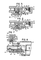
- Fig. 5 is a view similar to Fig. 4 showing the selector in a position to activate trigger control lever to block the trigger and sear;
- Fig. 6 is a view similar to Fig. 4 showing the selector in a position to block the trigger, sear and cocking piece;
- Fig. 7 is a sectional view taken along line 7-7 of Fig. 5;
- Fig. 8 is a fragmented plan view showing the selector in the position of Fig. 6 and further showing blocking plunger blocking the bolt handle..
- Fig. 9 is a partial side elevational view of a bolt action rifle including an alternative selector arrangement of the present invention;
- Fig. 10 is a partial plan view of the rifle of Fig. 9;
- Fig. ll..is an enlarged sectional view along line 3-3 of Fig. 10;
- Fig. 12 is a partial side elevational view of the alternative selector arrangement and trigger unit with the selector arrangement in the fire position;
- Fig. 13 is a partial side elevational view of the alternative selector arrangement in a lock position;
- Fig. 14 is a partial elevational view showing the alternative selector arm in the forward fire position;
- Fig. 15 is a sectional view along line 15-15 of Fig. 14;
- Fig. 16 is an exploded view of the receiver, selector unit, trigger, and associated parts of the alternative embodiment;
- Fig. 17 is a partial elevational view showing the alternative selector unit in the bolt handle restraining position; and
- Fig. 18 is a perspective view of the alternative selector unit.
- Referring to Figs. 1 and 2,
rifle 10 includes barrel 11, areceiver 12 secured to the rear of the barrel, a cylindricalbreech bolt assembly 13 mounted inreceiver 12 to the rear of and in axial alignment with barrel 11, abolt handle 14 secured to the rearward end of thebolt assembly 13, abolt head sleeve 16, acocking piece 17, areceiver tang 18 and astock 21. Rifle 10 also includestrigger 22,trigger guard 23, and a rotatable inactivatingselector unit 26.Unit 26 is mounted in the receiver and rotates about a vertical axis. - Turning to Fig. 3,
trigger 22 is pivoted abouttrigger pivot 28 withupper trigger arm 29 engaged insear notch 31 of.sear 32.Sear 32 is mounted aboutpivot 33 andspring 36 is interposed betweentrigger 22 andsear 32. The pulling oftrigger 22 to rotate it clockwise aboutpivot 28 causestrigger arm 29 to move out ofsear notch 31 permittingsear 32 to rotate clockwise aboutpivot 33 thus releasing cockingpiece 17. Cockingpiece 17 then moves forward under the force of a spring (not shown) to strike the rim of the cartridge (not shown) to fire the rifle. - With reference to Figs. 4-8, it is seen that
selector unit 26 is rotatably mounted to be turned to and held in three discrete positions determined by detent 37 (see Fig. 7) located on one (1) of the three (3)detent recesses Selector unit 26 includescylindrical body 43 carrying detent 37 in its lower portion (Fig. 7) and two slottedareas body 43 define respectively firstselector cam surface 46 and secondselector cam surface 47.Selector unit 26 also includes athumb piece 41.Slot area 44 has a thickness greater thancam follower 54 to accommodatefollower 54 therein (Fig. 4).Slot area 45 is less thick thanslot area 44 so that in the Fig. 6position cam follower 54 cannot enterslot area 45 but instead rides oncylindrical surface 50 ofselector body 43. Turning to Fig. 7, it is seen thatcam follower 54 housed betweenframe elements 55, has a thickness greater thanslot area 45. - On the other hand,
cam follower 56 with less thickness thanfollower 54 is accommodated inslot area 45 throughout the rotational operation ofselector unit 26. -
Trigger control lever 51 is pivotable aboutpivot 53. On oneend lever 51 carriesupper cam follower 54 andlower cam follower 56 while on the opposite endtrigger blocking finger 57 is located. Lever 51 is urged away fromtrigger 29 byspring 59. - Turning attention to Fig. 8, it is seen that cocking
piece 17 has a blockingnotch 60 in it for receivingoffset thumb piece 41 whenselector unit 26 is rotated to the position shown in Figs. 6 and 8. In this selector position, blockingplunger 52 is urged byselector 26 into bolt handle recess 61 to block movement of thebolt handle 14. Upon release ofplunger 52 byselector 26spring 64 withdrawsplunger 52freeing handle 14. - Summarizing,
selector unit 26 engages and movestrigger control lever 51 to block the trigger and it in turn the sear (see Figs. 4-6).Unit 26 also serves to restrict movement of cocking piece 17 (see Figs. 2 and 8) and actuates blockingplunger 52 to block movement of bolt handle 14 (Fig. 8). - In step-by-step
operation selector unit 26 is turned throughthumb piece 41 to a passive or neutral position causing detent 37 to snap into adetent recess 38 which placescylindrical body 43 which camsurfaces finger 57 oflever 51 does not block trigger 29 (see Fig. 4). The firearm can be fired in this selector mode. To restrict trigger movement and in turn sear movement, theselector unit 26 is moved to inactivating position number one wheredetent 37 is moved intorecess 39 causingsurface 46 to movecam follower 54 oflever 51 placinglever finger 57 against trigger arm 29 (see Fig. 5). In this position,trigger arm 29 is inactivated by being restrained from rotating clockwise about pivot 28 (as shown in Fig. 3). Thetrigger 22 cannot rotate and the sear cannot drop to fire the rifle. Alternatively,lever 51 and itsfinger 57 may be designed to block rotational movement ofsear 32. - Finally,
selector unit 26 is movable to inactivating position number two during which movement cylindical surface 5Q movescam follower 54 to retainlever 51 in its trigger- sear-restraining position. Asthumb piece 41 is moved to bringselector unit 26 to this thirdposition thumb piece 41 bears against bevelledsurface 63 causing blockingplunger 52 to move to the right intorecess 61 to block rotational movement ofhandle 14.Spring 64 is compressed during this movement. Upon the selector reaching this third position,thumb piece 41 is in blockingnotch 60 of pin striker 17 (cocking piece) to limit forward travel of striker 17 (see Figs. 6 and 8). - It will be noted that in
operation slot area 45,cam surface 47 andcam follower 56 operate to movelever 51 to the passive or neutral position of Fig. 4 whileslot area 44,cam surface 46,cylindrical surface 50 andcam follower 54 operate to movelever 51 into its blocking position and hold it there whenselector 26 is in positions number one and two as described above. - With reference to the alternative embodiment shown in Figs. 9-18 and, in particular, with reference first to Figs. 16 and 18, it is seen that
selector unit 26a (like selector 26) is rotatably mounted to be turned to and held in three discrete positions determined bydetent 70 mounted in adetent hole 71 inreceiver 12.Detent spring 72 urges detent 70 intorecesses selector unit 26a.Selector unit 26a includesthumb piece 77,cylindrical body portion 78 including configuredfoot portion 79.Foot portion 79carries notch 81 providing a configuration for engagement and disengagement with the trigger which will be explained.Trigger 82, pivotable aboutpivot axis 83, includesfinger piece 84, sear-engagingupper trigger arm 86 andtrigger extension 87 includingextension block 88. Also shown in Figs. 16 and 18 aretrigger side pieces sear spring 93,sear pin 94,selector cover plate 95, andrifle sight 96. - Turning to Figs. 12, 13 and 14, it is seen that when
selector unit 26a is in position A (Figs. 12 and 14), configuredfoot portion 79 ofselector 26a is positioned to accommodateextension block 88 thus permitting clockwise pivoting oftrigger 82, the release ofsear 92 and firing of the rifle (Fig. 12). As theselector thumb piece 77 is moved back from position A to points whererectangular block 88 is no longer able to be accommodated in notch 81 (such as position B in Fig. 14), a portion offoot portion 79 moves adjacent block 88 (with minimal clearance) to prevent, in these positions, any significant rotation oftrigger 82.Trigger 82 cannot in these positions be rotated clockwise to release sear 92 to fire the rifle. - Turning now to Fig. 17, the selector has been moved further rearward to place it in cocking
piece notch 60. Movement ofselector 26a to position C of Fig. 14 to lock bolt handle 14 is the same as operation ofselector 26 described above.
Claims (5)
whereby the rotation of the selector means (26) to the two positions actuates the elongated pivotable trigger and sear restraining means (51) to restrain trigger movement in the first position and to allow trigger movement in the second position.
whereby as the selector means (26) is rotated the extension means (28) and foot means (79) are engaged in said first position to allow trigger rotation to release the sear (32) and are not engaged in said position to permit trigger rotation to release the sear (32).
whereby as the selector means (26) is rotated (1) the configured foot portion (79) engages and disengages from the trigger extension (28) to block and unblock trigger rotation and (2) to engage, hold and release the cocking piece (17).
Applications Claiming Priority (2)
| Application Number | Priority Date | Filing Date | Title |
|---|---|---|---|
| US55596983A | 1983-11-29 | 1983-11-29 | |
| US555969 | 1983-11-29 |
Publications (3)
| Publication Number | Publication Date |
|---|---|
| EP0143625A2 true EP0143625A2 (en) | 1985-06-05 |
| EP0143625A3 EP0143625A3 (en) | 1986-01-02 |
| EP0143625B1 EP0143625B1 (en) | 1991-03-27 |
Family
ID=24219356
Family Applications (1)
| Application Number | Title | Priority Date | Filing Date |
|---|---|---|---|
| EP84308142A Expired - Lifetime EP0143625B1 (en) | 1983-11-29 | 1984-11-23 | Inactivating selector arrangement for bolt firearms |
Country Status (13)
| Country | Link |
|---|---|
| EP (1) | EP0143625B1 (en) |
| JP (1) | JPS60191199A (en) |
| KR (1) | KR920006523B1 (en) |
| AU (1) | AU580015B2 (en) |
| BR (1) | BR8405980A (en) |
| CA (1) | CA1231571A (en) |
| DE (1) | DE3484342D1 (en) |
| ES (1) | ES8604688A1 (en) |
| MX (1) | MX161955A (en) |
| NZ (1) | NZ210347A (en) |
| PH (1) | PH21909A (en) |
| PT (1) | PT79579B (en) |
| ZA (1) | ZA849040B (en) |
Cited By (1)
| Publication number | Priority date | Publication date | Assignee | Title |
|---|---|---|---|---|
| EP1106954A3 (en) * | 1999-12-03 | 2004-01-14 | Sommer, Gerd | Percussion pin safety for a rifle breech block |
Families Citing this family (1)
| Publication number | Priority date | Publication date | Assignee | Title |
|---|---|---|---|---|
| DE10211882B4 (en) * | 2002-03-18 | 2010-01-21 | Gottfried Prechtl | Securing long guns with a firing pin lock |
Family Cites Families (10)
| Publication number | Priority date | Publication date | Assignee | Title |
|---|---|---|---|---|
| DE78449C (en) * | G. LUGER, Berlin S.W., Belle-Alliancestr. 57 | Lock security for guns with bolt lock | ||
| GB191312619A (en) * | 1913-05-30 | 1913-09-18 | Francis Torriano Fisher | Improvements in or relating to Safety Attachments for Small Arms. |
| US2174971A (en) * | 1937-07-19 | 1939-10-03 | Western Cartridge Co | Safety mechanism for firearms |
| US2484977A (en) * | 1946-11-08 | 1949-10-18 | Hiram S Wilcox | Safety mechanism for firearms |
| US2648926A (en) * | 1950-08-02 | 1953-08-18 | Raymond O Ackerson | Rifle bolt sleeve and safety |
| US2869269A (en) * | 1955-06-02 | 1959-01-20 | Olin Mathieson | Safety mechanism for firearms |
| US2824402A (en) * | 1956-06-21 | 1958-02-25 | Joseph F Fischer | Breech bolt and firing pin safety mechanism for firearms |
| US4054003A (en) * | 1976-10-07 | 1977-10-18 | Wilson Hugh R | Firearm safety device |
| US4344246A (en) * | 1980-02-14 | 1982-08-17 | Remington Arms Company, Inc. | Firing pin block for firearm having a reciprocating breech bolt |
| AU553476B2 (en) * | 1983-05-02 | 1986-07-17 | Sturm, Ruger & Company, Inc | Safety mechanism for bolt action firearm |
-
1984
- 1984-11-13 CA CA000467620A patent/CA1231571A/en not_active Expired
- 1984-11-14 AU AU35400/84A patent/AU580015B2/en not_active Ceased
- 1984-11-20 ZA ZA849040A patent/ZA849040B/en unknown
- 1984-11-23 DE DE8484308142T patent/DE3484342D1/en not_active Expired - Lifetime
- 1984-11-23 EP EP84308142A patent/EP0143625B1/en not_active Expired - Lifetime
- 1984-11-26 BR BR8405980A patent/BR8405980A/en not_active IP Right Cessation
- 1984-11-26 MX MX203486A patent/MX161955A/en unknown
- 1984-11-27 PH PH31498A patent/PH21909A/en unknown
- 1984-11-27 NZ NZ210347A patent/NZ210347A/en unknown
- 1984-11-28 ES ES538038A patent/ES8604688A1/en not_active Expired
- 1984-11-28 KR KR1019840007478A patent/KR920006523B1/en not_active Expired
- 1984-11-29 JP JP59252767A patent/JPS60191199A/en active Granted
- 1984-11-29 PT PT79579A patent/PT79579B/en not_active IP Right Cessation
Cited By (1)
| Publication number | Priority date | Publication date | Assignee | Title |
|---|---|---|---|---|
| EP1106954A3 (en) * | 1999-12-03 | 2004-01-14 | Sommer, Gerd | Percussion pin safety for a rifle breech block |
Also Published As
| Publication number | Publication date |
|---|---|
| BR8405980A (en) | 1985-08-27 |
| DE3484342D1 (en) | 1991-05-02 |
| PT79579B (en) | 1986-08-05 |
| JPS60191199A (en) | 1985-09-28 |
| KR920006523B1 (en) | 1992-08-07 |
| NZ210347A (en) | 1986-07-11 |
| MX161955A (en) | 1991-03-08 |
| ES538038A0 (en) | 1986-02-01 |
| AU580015B2 (en) | 1988-12-22 |
| ZA849040B (en) | 1986-06-25 |
| EP0143625A3 (en) | 1986-01-02 |
| AU3540084A (en) | 1985-06-06 |
| PH21909A (en) | 1988-04-08 |
| ES8604688A1 (en) | 1986-02-01 |
| CA1231571A (en) | 1988-01-19 |
| PT79579A (en) | 1984-12-01 |
| EP0143625B1 (en) | 1991-03-27 |
| JPH0478919B2 (en) | 1992-12-14 |
| KR850004629A (en) | 1985-07-25 |
Similar Documents
| Publication | Publication Date | Title |
|---|---|---|
| US4569145A (en) | Inactivating selector arrangement for bolt action firearms | |
| US7726059B2 (en) | Lockable safety for firearm | |
| EP0185763B1 (en) | Ambidextrous safety mechanism | |
| US3641691A (en) | Grenade launcher with pivotally mounted barrel | |
| EP0529871B1 (en) | Lever arrangement for automatic pistol for positioning firing pin and for decocking | |
| US4627184A (en) | Ejector manually operable to rotate firing pin block for slide removal and disassembly | |
| US5081779A (en) | Firearm safety lock | |
| US5548914A (en) | Gun trigger mechanism | |
| US6889459B1 (en) | Model 1911 type firearm safety lock | |
| US5105569A (en) | Single shot pistol | |
| US20120167424A1 (en) | Ambidextrously operated bolt catch assembly | |
| US5821445A (en) | Loading lever assembly for hand-operated firearms | |
| CZ212192A3 (en) | Smallarm | |
| US4445292A (en) | Bolt latch for bolt-action firearm | |
| US4523510A (en) | Combined selector, safety and trigger assembly for automatic firearms | |
| US4305218A (en) | Safety mechanism for a firearm | |
| US12044492B2 (en) | Magazine latch | |
| US4870770A (en) | Safety mechanism for firearms | |
| US4730406A (en) | Bolt release trigger safety mechanism for firearms | |
| US5225611A (en) | Over/under shotgun safety arm | |
| EP0143625A2 (en) | Inactivating selector arrangement for bolt firearms | |
| EP0123747B1 (en) | Inactivating selector arrangement for bolt action firearms | |
| US3696543A (en) | Cylinder locking mechanism | |
| EP0143114B1 (en) | A modular hammer and safety assembly for a firearm | |
| EP0078867A1 (en) | Selective trigger unit for multiple barrel firearms |
Legal Events
| Date | Code | Title | Description |
|---|---|---|---|
| PUAI | Public reference made under article 153(3) epc to a published international application that has entered the european phase |
Free format text: ORIGINAL CODE: 0009012 |
|
| AK | Designated contracting states |
Designated state(s): BE DE FR GB IT LU NL |
|
| PUAL | Search report despatched |
Free format text: ORIGINAL CODE: 0009013 |
|
| AK | Designated contracting states |
Designated state(s): BE DE FR GB IT LU NL |
|
| 17P | Request for examination filed |
Effective date: 19860624 |
|
| 17Q | First examination report despatched |
Effective date: 19870430 |
|
| GRAA | (expected) grant |
Free format text: ORIGINAL CODE: 0009210 |
|
| AK | Designated contracting states |
Kind code of ref document: B1 Designated state(s): BE DE FR GB IT LU NL |
|
| ITF | It: translation for a ep patent filed | ||
| ET | Fr: translation filed | ||
| REF | Corresponds to: |
Ref document number: 3484342 Country of ref document: DE Date of ref document: 19910502 |
|
| PLBE | No opposition filed within time limit |
Free format text: ORIGINAL CODE: 0009261 |
|
| STAA | Information on the status of an ep patent application or granted ep patent |
Free format text: STATUS: NO OPPOSITION FILED WITHIN TIME LIMIT |
|
| 26N | No opposition filed | ||
| PGFP | Annual fee paid to national office [announced via postgrant information from national office to epo] |
Ref country code: LU Payment date: 19921020 Year of fee payment: 9 |
|
| PGFP | Annual fee paid to national office [announced via postgrant information from national office to epo] |
Ref country code: NL Payment date: 19921130 Year of fee payment: 9 |
|
| EPTA | Lu: last paid annual fee | ||
| PG25 | Lapsed in a contracting state [announced via postgrant information from national office to epo] |
Ref country code: LU Free format text: LAPSE BECAUSE OF NON-PAYMENT OF DUE FEES Effective date: 19931123 |
|
| PG25 | Lapsed in a contracting state [announced via postgrant information from national office to epo] |
Ref country code: NL Effective date: 19940601 |
|
| NLV4 | Nl: lapsed or anulled due to non-payment of the annual fee | ||
| PGFP | Annual fee paid to national office [announced via postgrant information from national office to epo] |
Ref country code: DE Payment date: 20000919 Year of fee payment: 17 |
|
| PGFP | Annual fee paid to national office [announced via postgrant information from national office to epo] |
Ref country code: GB Payment date: 20000925 Year of fee payment: 17 |
|
| PGFP | Annual fee paid to national office [announced via postgrant information from national office to epo] |
Ref country code: BE Payment date: 20001020 Year of fee payment: 17 |
|
| PGFP | Annual fee paid to national office [announced via postgrant information from national office to epo] |
Ref country code: FR Payment date: 20001129 Year of fee payment: 17 |
|
| PG25 | Lapsed in a contracting state [announced via postgrant information from national office to epo] |
Ref country code: GB Free format text: LAPSE BECAUSE OF NON-PAYMENT OF DUE FEES Effective date: 20011123 |
|
| PG25 | Lapsed in a contracting state [announced via postgrant information from national office to epo] |
Ref country code: BE Free format text: LAPSE BECAUSE OF NON-PAYMENT OF DUE FEES Effective date: 20011130 |
|
| REG | Reference to a national code |
Ref country code: GB Ref legal event code: IF02 |
|
| BERE | Be: lapsed |
Owner name: STURM RUGER & CY INC. Effective date: 20011130 |
|
| PG25 | Lapsed in a contracting state [announced via postgrant information from national office to epo] |
Ref country code: DE Free format text: LAPSE BECAUSE OF NON-PAYMENT OF DUE FEES Effective date: 20020702 |
|
| GBPC | Gb: european patent ceased through non-payment of renewal fee |
Effective date: 20011123 |
|
| PG25 | Lapsed in a contracting state [announced via postgrant information from national office to epo] |
Ref country code: FR Free format text: LAPSE BECAUSE OF NON-PAYMENT OF DUE FEES Effective date: 20020730 |
|
| REG | Reference to a national code |
Ref country code: FR Ref legal event code: ST |
|
| REG | Reference to a national code |
Ref country code: FR Ref legal event code: ST |