EP0143673A1 - Mit mehreren Kontaktgreifflächen versehene Greifer - Google Patents
Mit mehreren Kontaktgreifflächen versehene Greifer Download PDFInfo
- Publication number
- EP0143673A1 EP0143673A1 EP84401678A EP84401678A EP0143673A1 EP 0143673 A1 EP0143673 A1 EP 0143673A1 EP 84401678 A EP84401678 A EP 84401678A EP 84401678 A EP84401678 A EP 84401678A EP 0143673 A1 EP0143673 A1 EP 0143673A1
- Authority
- EP
- European Patent Office
- Prior art keywords
- freedom
- degrees
- gripper
- fingers
- finger
- Prior art date
- Legal status (The legal status is an assumption and is not a legal conclusion. Google has not performed a legal analysis and makes no representation as to the accuracy of the status listed.)
- Granted
Links
- 238000006073 displacement reaction Methods 0.000 claims description 22
- 238000013519 translation Methods 0.000 claims description 6
- 238000001514 detection method Methods 0.000 claims description 3
- 238000002955 isolation Methods 0.000 abstract description 2
- 238000005259 measurement Methods 0.000 description 24
- 230000000694 effects Effects 0.000 description 8
- 230000000712 assembly Effects 0.000 description 6
- 238000000429 assembly Methods 0.000 description 6
- 230000008901 benefit Effects 0.000 description 4
- 230000007246 mechanism Effects 0.000 description 4
- 230000003071 parasitic effect Effects 0.000 description 4
- 238000013459 approach Methods 0.000 description 3
- 239000003638 chemical reducing agent Substances 0.000 description 3
- 239000013598 vector Substances 0.000 description 3
- 210000000707 wrist Anatomy 0.000 description 3
- 238000005452 bending Methods 0.000 description 2
- 230000002146 bilateral effect Effects 0.000 description 2
- 238000009530 blood pressure measurement Methods 0.000 description 2
- 230000006835 compression Effects 0.000 description 2
- 238000007906 compression Methods 0.000 description 2
- 230000014509 gene expression Effects 0.000 description 2
- 230000005484 gravity Effects 0.000 description 2
- 230000003993 interaction Effects 0.000 description 2
- 230000002427 irreversible effect Effects 0.000 description 2
- 210000000056 organ Anatomy 0.000 description 2
- 241000207836 Olea <angiosperm> Species 0.000 description 1
- 230000009471 action Effects 0.000 description 1
- 230000006978 adaptation Effects 0.000 description 1
- 230000005540 biological transmission Effects 0.000 description 1
- 238000006243 chemical reaction Methods 0.000 description 1
- 230000000295 complement effect Effects 0.000 description 1
- 230000008878 coupling Effects 0.000 description 1
- 238000010168 coupling process Methods 0.000 description 1
- 238000005859 coupling reaction Methods 0.000 description 1
- 230000001955 cumulated effect Effects 0.000 description 1
- 230000001186 cumulative effect Effects 0.000 description 1
- 238000013461 design Methods 0.000 description 1
- 239000012530 fluid Substances 0.000 description 1
- 230000003100 immobilizing effect Effects 0.000 description 1
- 238000003780 insertion Methods 0.000 description 1
- 230000037431 insertion Effects 0.000 description 1
- 239000000463 material Substances 0.000 description 1
- 239000002184 metal Substances 0.000 description 1
- 238000000034 method Methods 0.000 description 1
- 238000005096 rolling process Methods 0.000 description 1
- 230000003068 static effect Effects 0.000 description 1
- 229920003051 synthetic elastomer Polymers 0.000 description 1
- 238000011144 upstream manufacturing Methods 0.000 description 1
Images


Classifications
-
- B—PERFORMING OPERATIONS; TRANSPORTING
- B25—HAND TOOLS; PORTABLE POWER-DRIVEN TOOLS; MANIPULATORS
- B25J—MANIPULATORS; CHAMBERS PROVIDED WITH MANIPULATION DEVICES
- B25J15/00—Gripping heads and other end effectors
- B25J15/08—Gripping heads and other end effectors having finger members
- B25J15/10—Gripping heads and other end effectors having finger members with three or more finger members
- B25J15/103—Gripping heads and other end effectors having finger members with three or more finger members for gripping the object in three contact points
-
- B—PERFORMING OPERATIONS; TRANSPORTING
- B25—HAND TOOLS; PORTABLE POWER-DRIVEN TOOLS; MANIPULATORS
- B25J—MANIPULATORS; CHAMBERS PROVIDED WITH MANIPULATION DEVICES
- B25J13/00—Controls for manipulators
- B25J13/08—Controls for manipulators by means of sensing devices, e.g. viewing or touching devices
- B25J13/081—Touching devices, e.g. pressure-sensitive
- B25J13/082—Grasping-force detectors
-
- Y—GENERAL TAGGING OF NEW TECHNOLOGICAL DEVELOPMENTS; GENERAL TAGGING OF CROSS-SECTIONAL TECHNOLOGIES SPANNING OVER SEVERAL SECTIONS OF THE IPC; TECHNICAL SUBJECTS COVERED BY FORMER USPC CROSS-REFERENCE ART COLLECTIONS [XRACs] AND DIGESTS
- Y10—TECHNICAL SUBJECTS COVERED BY FORMER USPC
- Y10S—TECHNICAL SUBJECTS COVERED BY FORMER USPC CROSS-REFERENCE ART COLLECTIONS [XRACs] AND DIGESTS
- Y10S294/00—Handling: hand and hoist-line implements
- Y10S294/902—Gripping element
-
- Y—GENERAL TAGGING OF NEW TECHNOLOGICAL DEVELOPMENTS; GENERAL TAGGING OF CROSS-SECTIONAL TECHNOLOGIES SPANNING OVER SEVERAL SECTIONS OF THE IPC; TECHNICAL SUBJECTS COVERED BY FORMER USPC CROSS-REFERENCE ART COLLECTIONS [XRACs] AND DIGESTS
- Y10—TECHNICAL SUBJECTS COVERED BY FORMER USPC
- Y10S—TECHNICAL SUBJECTS COVERED BY FORMER USPC CROSS-REFERENCE ART COLLECTIONS [XRACs] AND DIGESTS
- Y10S294/00—Handling: hand and hoist-line implements
- Y10S294/907—Sensor controlled device
Definitions
- the present invention relates to a gripper comprising multiple contact pads mounted on fingers able to move relative to a base part, in order to grip an object stably.
- gripping members are known which are used with various tools and in particular as a terminal manipulator or programmed robot member.
- the most common grippers have two fingers which perform the tightening either by remaining parallel to each other, or by pivoting around two axes integral with a base part. These two fingers generally terminate in planar contact surfaces, possibly elastic, making it possible to immobilize current objects by making a surface or linear contact on each surface.
- At least one of the clamping fingers ends in a V-shaped jaw allowing better grip of cylindrical or elongated objects.
- V-shaped jaws are arranged crosswise on both fingers, which allows objects of elongated shape to be taken in two different directions.
- the six components of the force tensor thus defined are measured using a unique system interposed between the gripper and the wrist of the manipulator or robot.
- the use of sensors with six degrees of freedom interposed between the wrist and the gripper leads to multiple difficulties resulting first of all from the extension of the gripping organ at this level. These difficulties also result from the mismatch between the point of application of the forces, located at the center of gravity of the object or at its point of contact with another object, and the point of measurement of the torsor of the forces generally located around ten centimeters. upstream on The articulated system.
- the subject of the invention is precisely a gripper with multiple contacts making punctual or pseudopunctual contacts with the object to be grasped, in order to improve the quality of grips, to allow the capture of the forces in the fingers of the gripper as close as possible to the points of contact, to authorize the taking of an object without moving it or exerting parasitic efforts, and finally to make it possible to carry out small displacements of the object seized compared to the frame of the gripper, without displacement of the fingers compared to the frame.
- a gripper with n contact pads mounted on fingers capable of moving relative to a frame, so as to grip an object of any three-dimensional shape, in a stable manner, characterized in that said pads have pseudopunctual contact surfaces with said object, the sum degrees of freedom existing between the latter and each of the contact surfaces being at most equal to 6 (n-1) -1, and the object seized, the contact pads, the fingers and the frame constituting an isostatic assembly such that The total sum of the degrees of freedom of all the links in this assembly is strictly equal to 6 (n-1).
- the condition of isostatism of the assembly including the object seized, the pads, the fingers and the frame therefore requires that one or more of the fingers present with the frame an additional degree of freedom.
- an additional degree of freedom can be introduced into one or more of connections finger-frame, to satisfy the condition of isostatis- me, transmitting the stresses between the clamping device and the finger by means of an elastic element, deformable in the direction corresponding to the tightening and opening of the fingers.
- an elastic element deformable in the direction corresponding to the tightening and opening of the fingers.
- an organ such as a spring in the finger-to-frame link makes it possible, unlike a kinematically equivalent bilateral link, to ensure that the force exerted by the pad on the object always has a positive component oriented towards the interior of the object according to normal to the surface thereof, at the point of contact between the object and the corresponding pad. This property is necessary for the good behavior of the object in the gripper.
- the condition of isostatism of the assembly constituted by the static gripper makes it possible to provide the gripper with six independent degrees of freedom for the object seized, an independent motor making it possible to control each movements corresponding to these six degrees of Freedom.
- this condition makes it possible to move the object without sliding and without contact breakage at the level of the pad-object contact points, without displacement of the fingers of the gripper relative to the frame.
- a real "gripper-manipulator" is thus produced, the mounting of which at the end of the robot carrier enables changes of orientation and position of small amplitude necessary, for example to the adjustment of two pieces. one in the other.
- the expressions skates with three, four or five degrees of freedom will be used to refer to the contact pads of the gripper allowing three, four or five movements or degrees of freedom of the object seized in relation to the pad considered in isolation. .
- this gripper comprises take a skate with three degrees of freedom and two skates with at most four degrees of freedom, and at least one link with one degree of freedom between the fingers and the frame, so that the said total sum of the degrees of freedom is equal to 12.
- the gripper comprises a pad with three degrees of freedom and two pads with four degrees of freedom, a link with one degree of freedom being provided between one of the fingers and the frame, a three-dimensional force sensor and an at least two-dimensional force sensor being mounted on the fingers carrying respectively the pad with three degrees of freedom and the pads with four degrees of freedom.
- this gripper comprises three pads with at most four degrees of freedom and a pad with at most five degrees of freedom, and at least one link with one degree of freedom between The fingers and the frame, so that the said total sum of the degrees of freedom is equal to 18.
- this gripper comprises three pads with four degrees of freedom and a pad with five degrees of freedom, a link with a degree of freedom being provided between one of the fingers and The frame, an at least two-dimensional force sensor and an at least one-dimensional force sensor being mounted on the fingers carrying respectively the pads with four degrees of freedom and the pad with five degrees of freedom.
- Each skate with three degrees of freedom can in particular be produced in the form of a pseudospheric piece attached to the corresponding finger.
- pseudospheric piece means any piece having in its useful part either the shape of a sphere or a torus, or an approaching shape.
- each skate with four or five degrees of freedom preferably comprises a pseudospheric piece mounted according to the case with one or two degrees of freedom on the corresponding finger.
- the pseudospheric part can in particular be either of revolution and mounted to rotate about an axis passing through its axis of revolution, or to be mounted in a sliding and non-rotating manner on a rod secured to the corresponding finger, elastic means then being provided between La piece and the finger in order to recall the pseudospheric piece towards a central part of the rod.
- the pseudospheric part can also be connected to the corresponding finger by two parallel spring blades of the same length defining a deformable parallelogram.
- the pseudospheric part can be constituted by a ball mounted in a spherical bearing.
- the skate can also be constituted in the same way as a skate with four degrees of freedom, the pseudospheric part also having, as the case may be, an additional degree of freedom of rotation around its axis of revolution or translation.
- the pseudospheric part can also be connected to the corresponding finger by two pairs of parallel spring blades of the same length defining two deformable parallelograms in two orthogonal directions.
- FIG. 1 shows a three-digital gripper with three contact pads each defining a point contact or pseudopoint.
- This gripper comprises three rectilinear fingers 10a, 10b and 10c parallel to each other, of square section and of the same length. These fingers are movably mounted on a base piece or frame 12 by which the gripper is fixed to the manipulator or the robot.
- each finger 10a, 10b and 10c is provided, on the side of the base part 12, with a displacement and guide part 14a, 14b and 14c respectively.
- Each of these parts 14a, 14b and 14c comprises a nut in LequeL is received a screw 16a, 16b, 16c and a sleeve in LaqueLLe is received a guide rod 18a, 18b and 18c respectively.
- the screws and the guide rods are mutually parallel and perpendicular to the fingers 10a, 10b and 10c. They thus define for the latter parallel displacements which are controlled by three independent geared motors 20a, 20b and 20c actuating the screws 16a, 16b and 16c.
- the screws 16a, 16b, 16c, the guide rods 18a, 18b, 18c, as well as the gearmotors 20a, 20b, 20c are mounted on the base part 12.
- Each of the fingers 10a, 10b and 10c can thus move independently of the other fingers.
- one of the screws such as the screw 16a and the corresponding rod 18a are placed respectively at equal distance between the two other screws 16b and 16c and between the two other guide rods. 18b and 18c.
- each of the fingers 10a, 10b and 10c carries at its end a gripping pad 22a, 22b and 22c respectively.
- Each of these pads defines a spherical or pseudospheric external surface defining with Object 0 to grasp point or pseudopunctual contacts with friction A, B and C.
- These three contact points define a deformable triangle located practically in the end plane of the three fingers, that is to say in a plane perpendicular to the fingers.
- the point contacts defined by the pads 22a, 22b and 22c are friction contacts which can be obtained in practice by making these pads in a material having a high coefficient of friction such as a more or less hard synthetic elastomer or by pieces striated metal.
- the shoe 22c is also mounted rotating on an axis 24c fixed to the end of the finger 10c, for example in the extension thereof.
- the gripper three contact pads therefore comprises a pseudospherical pad contact 22a with three degrees of li - dom and two pads 22b contact and 22c having a degree of Additional freedom, that is to say four degrees of freedom to contact the object.
- These four degrees of freedom correspond to the three degrees of freedom available to the object when it is in contact with a fixed sphere such as the sphere 22a, increased by the rotation of the pad 22b or 22c and the object which is at its contact around the axis 24b or 24c.
- the invention also relates to the case where two or three pads are fixed, its preferred form relates to the case in which one of the pads allows three degrees of freedom while the other two allow four degrees of freedom. .
- the gripper defines eleven degrees of freedom cumulated at the three contact points. These eleven degrees of freedom accumulated satisfy the formula according to which The number of degrees of freedom accumulated existing between the object seized and each shoe of a gripper with n points of contact is equal to 6 (n-1) -1.
- a first gauge bridge 26, 28 (only the gauge 26 being visible) is placed on two opposite faces of the finger 10a and a second gauge bridge 30, 32 (only the gauge 30 being visible ) is placed on the two other faces of this finger.
- the gauge bridge 26, 28 makes it possible to measure the force according to the arrow F1, orthogonal to the screw 16a.
- the second gauge bridge 30, 32 makes it possible to measure the force according to arrow F2 perpendicular to arrow F1, that is to say parallel to screw 16a.
- the point of measurement of the forces F1 and F2 is constituted by any point located along the axis of the finger 10a, and in particular by the center of the pad 22a as shown in FIG. 1.
- the forces F1 and F2 are always directed towards the other fingers.
- the axial force can take values in the direction of the traction F3 or in the direction of the thrust F'3.
- the three fingers 10a, 10b and 10c being parallel and their displacement vectors also being parallel, the nine forces thus measured are all parallel in pairs with each other, which makes it possible to calculate simple way The torsor of the efforts.
- the additional degree of freedom enjoyed by the pads 22b and 22c makes it possible to carry out redundant force measurements, which are not subject to constraints related to the relative movements between the fingers. The effort torsor can thus be more easily identified.
- the measurement on the finger 10c can be limited for example to a measurement of the bending F4 parallel to the screw 16b by means of a bridge.
- gauges 34, 36 (only the gauge 34 being visible) comparable to the bridge of gauges 30, 32.
- the bridge of gauges 34, 36 is also used to measure the Longitudinal effort F5, F'5 transmitted to the finger 10b by the pad 22b.
- finger 10c can be fitted with a bridge of gauges 38, 40 (only gauge 38 being visible) arranged in a comparable manner to gauges 26 and 28, so as to allow the measurement of the flexion F6 perpendicular to the screw 16c and the Longitudinal effort F7 or F'7 exerted on the finger 10c. Seven measurements are thus made making it possible to reconstruct the torsor of the forces and the seventh force which corresponds to the tightening proper.
- the fourth degree of freedom can be obtained by mounting a pseudospheric pad teL that 22'b in a sliding but non-rotating manner on a straight rod 24'b of prismatic section (triangular on the figure) fixed to the end of the corresponding finger 10b by means of a fork 42.
- the rod 24'b is arranged along an axis of revolution of the shoe 22'b, like the rods 24b and 24c in FIG. 1.
- the sliding rod 24'b is perpendicular to finger 10b as illustrated in FIG. 2a, the shoe 22'b is given an additional degree of freedom which can be compared to that achieved by the rotation of the shoe 22b in FIG. 1.
- the contact obtained between the pads at four degrees of freedom and the object is always located in the same plane, regardless of where is located The point of contact.
- two compression springs 44 are preferably placed around the rod 24'b on either side. skate 22'b.
- the latter is thus automatically refocused towards a central part of the rod when it is not in contact with an object. It thus has in all cases a certain travel when the tightening or small displacements of the object, when it is caught in the gripper, require it.
- the pseudospherical shoe 22 "b is connected to the end of the finger 10b by two spring blades 46 parallel and of the same length. More precisely, the spring blades are fixed on either side of the shoe 22 "b, along an axis of revolution thereof, and they are fixed on a block 48 soli from the tip of the finger 10b.
- the two blades 46 thus define with the axis of the pad 22 "b and with the block 48 a deformable parallelogram.
- the pad 22" b therefore has an additional degree of freedom comparable to the degree of additional freedom of the pad 22'b in the figure. 2a, although its displacement takes place on an arc of a circle and not along a straight line.
- the fixed shoe 22a in the form of a shoe mounted in a rotary manner on an axis parallel to the axes 24b and 24c and to control the rotation of the shoe by means of a rotary actuator.
- this actuator is not implemented, the pad 22a behaves like a fixed pad and all that has been said previously with regard to FIG. 1 remains valid.
- the implementation of this rotary actuator has the effect of rotating the shoe 22a about an axis parallel to the axes 24b and 24c, which causes a rotation of the part in the gripper .
- this part is a cylinder of revolution with an axis parallel to the fingers of the gripper, the implementation of the actuator thus makes it possible to obtain the rotation of The part around its axis.
- the gripper according to the invention allows, on the one hand, a better adaptation of force sensors on the fingers of the gripper and, on the other hand, the addition of orientation movements according to axes perpendicular to the degrees of freedom specific to each skate.
- FIG. 1 has the advantage of making it possible to carry out an overall displacement of the object in the direction of movement of the fingers.
- the gripper of FIG. 1 quickly becomes unsuitable since, due to the parallel movements of the fingers 10a, 10b and 10c, the contact points of the pads 22b and 22c cannot in no case approach more than the distances between the two screws which ensure their guidance and their displacement.
- FIG 3 an alternative embodiment of the gripper of Figure 1 according to LaqueLLe
- the fingers 10a, 10b and 10c which are always parallel to each other, are the object of radial translational movements , for example at 120 ° from each other, with respect to an axis of rotational symmetry of order three XX '.
- the control screws 16'a, 16'b and 16'c, as well as the guide rods 18'a, 18'b and 18'c are arranged radially as illustrated in Figure 3.
- the screws and The rods must then be placed at different levels along the axis XX ', so that the fingers 10a, 10b and 10c must be of different lengths if it is desired that the pads 22a, 22b and 22c are placed on the same level.
- the clamping can be controlled by means of a single actuator.
- an object can be grasped by acting on the actuator controlling the third finger.
- the object can only be grasped when it is in contact with the first pads, 'by tightening the third.
- the gripper cannot grasp the object without risking moving it or exerting even minimal effort on this object.
- the mechanical structure of a gripper comprising a single actuator is particularly simple.
- the displacement in translation of the fingers along screws and guide rods can be replaced either by a system of parallel fingers mounted on deformable paraLearograms, or by pivoting fingers. It is thus possible to produce a gripper with a simpler clamping movement suitable for smaller and more tolerant objects.
- a exemplary embodiment of a gripper teL is shown in FIG. 4.
- FIG. 4 shows a bidigital gripper making it possible to carry out a grip at three points using a single actuator.
- the gripper of FIG. 4 comprises a basic part 112 on which there are two small parallelograms each formed by two rods 150a and 150b respectively operating in bending and in torsion for each of the finger-holding blocks 152a. and 152b.
- blocks 152a and 152b respectively carry a finger 110a similar to finger 10a in FIG. 1 and an extension 154b carrying pads 122b and 122c similar to the pads 22b and 22c of FIG. 1, through a single bar 156b.
- the extension 154b remains constantly parallel to the finger 110a under the effect of the parallelograms defined by the links 150a and 150b.
- the bar 156b is fixed in its middle on the extension 154b, perpendicular to the plane passing through it and by the arm 110a, and carries at its ends the pads 122b and 122c.
- the two parts 110b and 110c thus formed on the bar 156b thus resemble the fingers 10b and 10c in FIG. 1.
- the finger 110a carries a pseudospheric fixed shoe 122a.
- the pads 122b and 122c are mounted to rotate respectively on the axes 124b and 124c parallel to the extension 154b.
- solutions described above with reference to FIGS. 2a and 2b could also be transferred to the embodiment of FIG. 4.
- the gripper is made isostatic by the introduction of an elastic element between the actuating device associated with the frame 112 and the finger 110a, this element being deformable in the direction corresponding to the tightening of this finger.
- the support of the pads 122b and 122c by the extension 154b could be produced in a different way and in particular by means of two parallel fingers arranged in the extension of the axes 124b and 124c.
- strain gauge bridges are preferably mounted on the finger 110a and on the parts 110b and 110c of the bar 156b so as to be able to determine the torsor of the forces as well as the clamping force.
- there are provided on finger 110a two bridges of strain gauges 126, 128 and 130, 132 (only the gauges 126 and 130 being visible) constituting a three-dimensional force sensor.
- the part. 110b of the bar 156b may include a bridge of gauges 134, 136 (only the gauge 134 being visible) measuring the force along the axis 124b of the shoe 122b.
- the part 110c of the bar 156b then carries a bridge of gauges 138, 140 (only the gauge 138 being visible) measuring the force perpendicular to the axis 124c.
- the combination of the two gauge bridges carried by the bar makes it possible to measure the force along the direction defined by it.
- each of the parts 110b and 110c of the bar 156b may include two gauge bridges and thus allow checks by symmetry for the calibration of the assembly.
- the various embodiments described relate to grippers with three contact points. However, the invention also applies to grippers having a higher number of contact points.
- the gripper according to the invention can also include four contact points.
- This gripper is particularly suitable for grasping objects of shape close to the sphere which could not be grasped using the grippers described above, since the application of a large clamping force would risk leading to a sliding of the object, which could then escape.
- the contact points A, B, C and D defined by the gripper approach the four vertices of a tetrahedron.
- Points A, B and C are obtained by The coming into contact on Object 0 of three pads 222a, 222b and 222c mounted at the ends of three articulated fingers 210a, 210b and 210c.
- Point D is obtained by the coming into contact of a new shoe 222d supported by an additional finger 210d which, in the form shown in FIG. 5, is a telescopic finger.
- each finger 210a, 210b and 210c is shown here schematically in the form of a triangle on LequeL.
- the three fingers 210a, 210b and 210c The pivoting of each finger on the piece 212 is controlled by means of an actuator 220a, 220b and 220c.
- Each of the fingers is bent towards the finger 210d, so as to be able to contain an object 0 of approximately spherical shape without risking accidental contact on the finger proper.
- Each finger 210a, 210b and 210c thus defines a plane perpendicular to its pivot axis and disposed radially relative to the axis of the gripper, which merges with the axis of the fourth finger 210d.
- the contact pad 222a defines a point contact with friction at four degrees of freedom. To this end, it takes the form of a pseudo-sphere rotatably mounted around an axis 224a substantially perpendicular to the plane of the finger 210a. The pivot axis of the shoe 222a is thus approximately parallel to the pivot axis of the finger 210a.
- the pads 222b and 222c each define four degrees of freedom for the object 0. More precisely, they are constituted by pseudo-spheres mounted rotating on axes 224b and 224c respectively arranged in the extension of the straight end of the corresponding finger.
- the axes 224b and 224c are thus approximately orthogonal to the pivot axes of the fingers which support them.
- the object to be grasped is inside the gripper of FIG. 5, after the three pads 222a, 222b and 222c have been brought into contact with it, the object can no longer pivot. Indeed, if the pad 222a pivoted around an axis similar to the pivot axes of the pads 222b and 222c, the object for should rotate around an axis approximately coincident with the axis of symmetry of the gripper. However, mounting the shoe 222a on an axis that does not intersect this axis of symmetry prohibits such rotation of the object.
- the object 0, of approximately spherical shape can therefore have no rotational movement when it is in contact with friction on the pads 222a, 222b and 222c.
- the fourth contact point defined by the pad 222d define five degrees of freedom and serve only to transmit the tightening force. Consequently, the shoe 222d preferably consists of a real sphere mounted in a spherical bearing 258.
- the number of cumulative degrees of freedom of each of the contact points is equal to 17, which satisfies the formula stated above.
- the reaction mode Readout shown in Figure 5 corresponds to The best possible configuration according to LaqueLLe only a tightening constraint applies to the system constituted by the object and by the gripper.
- the condition of isostatism is fulfilled by placing a torsion spring between one of the actuators 220a, 220b and 220c and the corresponding finger 210a, 210b and 210c, or by placing a spring between the finger 210d and its actuator.
- This configuration allows the best arrangement of force sensors to determine the force torsor.
- a force sensor bridge 226, 228 placed on the finger 210a, to measure the force exerted along the axis pivoting shoe 220a.
- another bridge of sensors 230, 232 mounted on the other faces of the finger 210a makes it possible to measure the force applied perpendicular to the axis of the end of the finger, in the plane of this one. It is not useful to measure the tensile force according to the finger 210a accessible by the linear combination between these two sensor bridges, because of the degree of freedom conferred on the pad 222a around its axis of rotation.
- a bridge of sensors 234, 236 (only The sensor 234 being visible) is mounted on the arm 210b in order to measure the bearing force at B in the plane of the finger and the tensile force along of the pivot axis of the shoe 222b.
- a sensor bridge 238, 240 (only The sensor 238 being visible) is mounted on the opposite faces of the upper segment of the finger 210c, in order to allow the same measurements to be made on the latter.
- the pad 222b which corresponds to the equivalent of a frictionless support thanks to its spherical bearing 258, is the object of a pressure measurement according to the thrust axis of the telescopic finger 210d.
- the degrees of freedom authorized by the contact pads as they have just been described with reference to FIG. 5 make it possible to measure the torsor efforts in the most decoupled manner possible in the fingers of the gripper.
- the invention is not limited to this optimal solution and also relates to any gripper in LequeL
- the contact pads define a slightly lower number of degrees of freedom, provided that the number of degrees of freedom of the assembly object- pads-fingers-frame remains equal to 6 (n-1).
- a second torsion spring is then placed between a second actuator and the corresponding finger.
- the gripper of FIG. 5 is designed such that the object is positioned in the gripper by acting on the three fingers 210a, 210b and 210c, while the tightening of the object can be achieved by acting on the single telescopic finger 210d.
- this last finger is preferably provided with a support spring permanently applying the shoe 222d to the object.
- the 222d skate with five degrees of freedom has been described as consisting of a hard sphere mounted in a spherical bearing generally produced by a bed of balls or by a fluid bearing.
- This embodiment of the pad 222d is not however limiting and it can be seen by referring to FIGS. 6a and 6b that the pad with five degrees of freedom can also be produced in a different manner.
- FIG. 6a there is shown a shoe 222'd having a pseudospheric outer surface.
- This shoe 222'd is rotatably mounted on an axis 260 disposed parallel to an end block 248 secured to the finger 210d,
- the axis 260 being connected to the block 248 by two spring blades 246 parallel and of the same length defining with Axis 260 and with block 248 a deformable parallelogram.
- this variant embodiment of FIG. 6a is similar to the variant embodiment of the skate with four degrees of freedom of FIG. 2b, the additional degree of freedom being obtained by mounting the skate in a rotating manner on an axis 260 connected to the corresponding finger by the two spring blades.
- the second variant of the contact pad with five degrees of freedom shown in FIG. 6b is also similar to the variant of FIG. 2b.
- a pad 222 "d having a pseudospheric external surface and connected to a block 248 disposed parallel to the axis of the pad by two spring blades 246.
- the additional degree of freedom is obtained by making the block 248 mobile with respect to a block 262 fixed to the end of the finger 210d.
- the blocks 248 and 262 being parallel to each other, this mobility is obtained by connecting them by two spring blades 264 parallel and of the same length which define with blocks 248 and 262 a deformable parallelogram in a plane perpendicular to the plane of the parallelogram defined by Spring blades 246.
- the actuator making it possible to control the finger 210d is preferably a hydraulic or pneumatic actuator, while the actuators 220a, 220b and 220c may be of more conventional design. These last three actuators can also be replaced by a single actuator simultaneously controlling the tightening of the three fingers, for example by using known linkage means. Finally, in the particular case of grippers intended to grasp objects of spherical shape, it may be good to synchronize the movements of the four fingers. To this end, the movement of the finger 210d performing the tightening can be controlled by an articulated device performing at the same time the tightening of the other three fingers according to techniques well known in articulated systems.
- the gripper of FIG. 5 however has the disadvantage that the amplitude of the movement of the fingers remains limited and does not allow objects of very variable sizes to be grasped. Furthermore, since the fingers are not parallel to each other, it is necessary to know the position of each finger in order to be able to resolve the torsor of the forces.
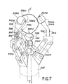
- FIG. 7 shows a preferred embodiment of a gripper with four contact points.
- the three main fingers are kept permanently parallel to each other using parallelograms of the same type as those which have been described previously with reference to FIG. 4.
- the gripper of FIG. 7 has a unique clamping mechanism.
- the gripper comprises a base part 312 on LaqueLLe are articulated three fingers 310a, 310b and 310c, by means of three pairs of links 350a, 350b and 350c.
- Each pair of rods defines a deformable parallelogram in a radial plane with respect to the ternary axis of symmetry XX 'of the gripper.
- the three fingers 310a, 310b and 310c thus move in parallel with one another in three radial planes located at 120 °, one with respect to the other around the axis XX '.
- the fourth finger 310d is, as in FIG. 5, a telescopic finger arranged along the axis of symmetry XX '.
- the displacement of the finger 310d is coupled to that of the other three fingers by three links 366 articulated both on the finger 310d and on the link closest to each of the pairs of links 350a, 350b and 350c.
- the inclinations of these different links are calculated so that the resulting coupling of the fingers allows the four pads to be united around an object whose size is as small as possible.
- the different pads are made in a manner comparable to that which has been described with reference to FIG. 5.
- the finger 310a supports a pseudospheric pad 322a so as to rotate about an axis 324a substantially perpendicular to the radial plane in LequeL moves the corresponding finger.
- the pads 322b and 322c carried respectively by the fingers 310b and 310c are also of pseudospheric shape and pivotally mounted on axes such as 324b located in the extension of the part upper finger corresponding, that is to say in the radial plane of movement of the finger, about 60 ° relative to the axis of symmetry XX '.
- the shoe 322d carried by the finger 310d is constituted by a rigid sphere received in a spherical bearing 358.
- condition of isostatism of the assembly is carried out as in FIG. 5, by placing for example a compression spring between the pad 322d and the part of the finger 310d on which the links 366 are articulated.
- the embodiment of Figure 7 has the advantage of allowing the establishment of the strain gauges used to determine the torsor of the forces at the base of each of the fingers 310a, 310b and 310c, that is to say say in directions which remain constantly parallel or orthogonal to the axis of symmetry XX 'of the gripper.
- gauges 326, 328 placed on finger 310a, which measure the force perpendicular to the plane of movement of this finger and gauges 330 and 332 (only gauge 330 being visible) which measure the force in this plane parallel to the axis of symmetry XX '.
- the finger 310b carries in its part parallel to the axis XX ′ strain gauges 334 and 336 measuring the force in the plane of movement of the finger 310b, in a direction perpendicular to the axis XX ′ and in the sense of traction.
- gauges are also placed on the part of the finger 310c parallel to the axis XX ', in order to perform the same type of measurement as on the arm 310b.
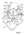
- the gripper of Figure 8 comprises a frame 412 on LequeL are mounted three identical modules. Each of these modules is made up of a gearmotor assembly for tightening control 420a, 420b, 420c, the housing of which is fixed to the frame 412, of a finger 410a, 410b, 410c pivotally mounted on the frame 412 by means of the Corresponding gearmotor and a contact pad 322a, 322b, 322c mounted at the end of the corresponding finger.
- a gearmotor assembly for tightening control 420a, 420b, 420c the housing of which is fixed to the frame 412, of a finger 410a, 410b, 410c pivotally mounted on the frame 412 by means of the Corresponding gearmotor and a contact pad 322a, 322b, 322c mounted at the end of the corresponding finger.
- the axes of articulation of the fingers 410a, 410b, 410c on the frame 412 which correspond to the axes of the geared motors, are arranged so as not to introduce additional parasitic movements of the object 0 gripped by the pads.
- the object-pad contact points can be in a plane parallel to that of the pivot axes of the fingers, the latter being parallel and, for two of them, aligned, or else that two contact points can define a segment parallel to the axis of articulation of the third finger, the axes of the fingers being parallel to each other and, for two of them, aligned.
- each of the pads 322a, 322b, 322c can be considered to be fixed to the end of the corresponding finger. Its substantially hemispherical shape allows it to come into punctual contact with an object of any shape by defining with this object a friction connection at three degrees of freedom.
- each of the geared motors 420a, 420b, 420c therefore actuates the corresponding finger by means of an elastic element (spring) of torsion.
- Figures 8 and 9 differs essentially from the previous ones by the fact that the gripper has six additional degrees of freedom allowing, with the help of associated actuators, to orient and position with a low amplitude The object entered 0, relative to the base 412 of the gripper, without any action on the gearmotor assemblies 420a, 420b, 420c controlling the tightening and the opening. Recall that such a possibility is permitted by the isostatic nature of the gripper.
- each of the fingers comprises a motor assembly 470a, 470b, 470c controlling the translation of the corresponding pad 422a, 422b, 422c along the axis LongitudinaL of the finger and a motor assembly 472a, 472b, 472c controlling the rotation of the corresponding pad around this axis.
- each of the fingers comprises a first part 410'a, 410'b, 410'c driven in rotation by the corresponding assembly 420a, 420b, 420c and supporting the housing of the assembly The motor 470a, 470b, 470c, respectively.
- the housing of the motor assembly 472a, 472b, 472c is slidably received in the first part 410'a, 410'b, 410'c, along an axis perpendicular to the axis of the corresponding assembly 420a, 420b, 420c and defining the axis of the finger.
- a rack 474a, 474b, 474c is secured to each of the shells of the motor assemblies 472a, 472b, 472c, parallel to the axis of the finger.
- a pinion (not shown) integral with the output shaft of each of the geared motors 470a, 470b, 470c meshes with the corresponding rack, so that the implementation of any one of these geared motors has the effect of move the corresponding pad parallel to the axis of the finger.
- the retation movement of each of pads around the axis of the corresponding finger is obtained by mounting each pad 422a, 422b, 422c on the bent end at right angles to a second rod-shaped part 410 "a, 410" b, 410 "c of the finger corresponding, this part being integral with the output shaft of the geared motor 472a, 472b, 472c.
- Geared motor assemblies 420a, 420b, 420c controlling Clamping and opening movements of the fingers
- Geared motor assemblies 470a, 470b, 470c controlling Movements of small amplitude of the pads along the axis of the fingers
- the assemblies gearmotors 472a, 472b, 472c commander
- the small amplitude swivels of the pads around the axis of the fingers are made identically. Only One 472a of these assemblies will therefore be described in more detail with reference to FIG. 9.
- the geared motor assembly 472a includes a cylindrical housing 476 in which are housed end to end a relative position encoder (pulse generator) 484, an electric motor 478, a speed reducer 480 and an encoder of absolute angular position 482. More precisely, the rotor of the motor 478 is integral with a shaft 486 carrying at one end the disc 484a of the pulse generator 484 and at its opposite end the driving gear 480a of the reducer 480, which in this case is of the so-called "Harmonic Drive” type.
- the driven gear 480b of this reducer is integral with an output shaft 488. The latter is itself connected to the rod-shaped part 410 "a of the corresponding finger by a torsion spring 490 ensuring better resolution of L
- the disc 482a of the position encoder 482 is fixed directly to the rod 410 "a.
- the spring 492 moving the shoe perpendicularly to the axis of the finger, in the direction of the object to be grasped, The coming into contact of the shoe on the latter immediately has the effect (given the weakness of the force exerted by the spring ) to bring the pad against the stop 494.
- This situation is detected by any means such as an analog system or, as shown, an all-or-nothing electrical contact 496.
- This system is connected to the control circuit, in order to '' ensure the immediate cessation of kinematics.
- this contact detection system does not introduce any additional degree of freedom at the level of the pads since, when an object is in the gripper, the pads are in abutment against surfaces such as 494 formed at the ends of the fingers.
- the invention is not limited to the embodiments which have just been described by way of example, but covers all the variants thereof.
- all the variant embodiments of skates with four degrees of freedom described with reference to FIGS. 1, 2a and 2b can be applied to skates with four degrees of freedom used in the grippers of FIGS. 5 and 7.
- teachings of the gripper with three contact points of FIG. 4 can be transposed in The grippers with four contact points of FIGS. 5 and 7, two of the three upper contact fingers then being supported by an articulated finger unique.
- the section of the fingers of the gripper can take any other form allowing the arrangement of the bridges of gauges, when these exist, on substantially flat faces and oriented so as to measure the forces in directions. allowing to resolve the torsor of efforts as simply as possible.
- the gauge bridges can also be deleted, in particular when the sum of the degrees of freedom existing between each skate and the object is less than 6 (n-1) -1.
- the section of the fingers can then be arbitrary.
Landscapes
- Engineering & Computer Science (AREA)
- Robotics (AREA)
- Mechanical Engineering (AREA)
- Human Computer Interaction (AREA)
- Manipulator (AREA)
Applications Claiming Priority (2)
| Application Number | Priority Date | Filing Date | Title |
|---|---|---|---|
| FR8314084A FR2551389B1 (fr) | 1983-09-02 | 1983-09-02 | Prehenseur a patins de contact multiples |
| FR8314084 | 1983-09-02 |
Publications (2)
| Publication Number | Publication Date |
|---|---|
| EP0143673A1 true EP0143673A1 (de) | 1985-06-05 |
| EP0143673B1 EP0143673B1 (de) | 1988-01-13 |
Family
ID=9291959
Family Applications (1)
| Application Number | Title | Priority Date | Filing Date |
|---|---|---|---|
| EP84401678A Expired EP0143673B1 (de) | 1983-09-02 | 1984-08-16 | Mit mehreren Kontaktgreifflächen versehene Greifer |
Country Status (5)
| Country | Link |
|---|---|
| US (1) | US4653793A (de) |
| EP (1) | EP0143673B1 (de) |
| JP (1) | JPS6062492A (de) |
| DE (1) | DE3468642D1 (de) |
| FR (1) | FR2551389B1 (de) |
Cited By (4)
| Publication number | Priority date | Publication date | Assignee | Title |
|---|---|---|---|---|
| EP0237336A3 (en) * | 1986-03-13 | 1988-01-07 | Lord Corporation | Apparatus and method for handling articles in automated apparatus and method for handling articles in automated assembly processes assembly processes |
| AT388528B (de) * | 1987-03-25 | 1989-07-25 | Oesterr Forsch Seibersdorf | Greifer |
| DE3836439A1 (de) * | 1988-10-26 | 1990-05-03 | Mueller Arnold Gmbh Co Kg | Greifvorrichtung |
| WO2021118385A1 (ru) * | 2019-12-10 | 2021-06-17 | федеральное государственное автономное образовательное учреждение высшего образования "Московский физико-технический институт (национальный исследовательский университет)" | Захватное устройство и способ его работы |
Families Citing this family (76)
| Publication number | Priority date | Publication date | Assignee | Title |
|---|---|---|---|---|
| CA1276710C (en) * | 1983-11-30 | 1990-11-20 | Kazuo Asakawa | Robot force controlling system |
| US4791537A (en) * | 1984-07-02 | 1988-12-13 | Irvin Industries, Inc. | Vehicle accessory assembly with sliding door for mounting on a visor or other interior panel |
| US5000652A (en) * | 1986-09-22 | 1991-03-19 | International Business Machines Corporation | Wafer transfer apparatus |
| US4770455A (en) * | 1986-10-21 | 1988-09-13 | The United States Of America As Represented By The Administrator Of The National Aeronautics And Space Administration | Passively activated prehensile digit for a robotic end effector |
| US5161846A (en) * | 1988-08-23 | 1992-11-10 | Canon Kabushiki Kaisha | Hand apparatus |
| US5501498A (en) * | 1988-08-31 | 1996-03-26 | The Trustees Of The University Of Pennsylvania | Methods and apparatus for mechanically intelligent grasping |
| US4957320A (en) * | 1988-08-31 | 1990-09-18 | Trustees Of The University Of Pennsylvania | Methods and apparatus for mechanically intelligent grasping |
| US5177563A (en) * | 1989-02-01 | 1993-01-05 | Texas A&M University System | Method and apparatus for locating physical objects |
| US5161847A (en) * | 1989-09-07 | 1992-11-10 | Canon Kabushiki Kaisha | Robot hand |
| US5052736A (en) * | 1990-02-02 | 1991-10-01 | The University Of Maryland | Modular dexterous hand |
| US5120101A (en) * | 1990-12-17 | 1992-06-09 | The United States Of America As Represented By The Administrator Of The National Aeronautics And Space Administration | Rolling friction robot fingers |
| JPH0569374A (ja) * | 1991-09-14 | 1993-03-23 | Toyota Central Res & Dev Lab Inc | 指モジユール、指モジユール構造、ロボツトハンドおよび指モジユールの信号検出取出方法 |
| JPH06155358A (ja) * | 1992-11-27 | 1994-06-03 | Daikin Ind Ltd | ロボットハンド |
| DE4411319C1 (de) * | 1994-03-28 | 1995-06-01 | Ipea Inst Fuer Prozesadaptive | Parallelgreifer mit Spindelantrieb |
| JPH0976033A (ja) * | 1995-09-11 | 1997-03-25 | Murata Mach Ltd | ワークホルダの異常検出装置 |
| US6273483B1 (en) | 1996-03-28 | 2001-08-14 | Mcmaster University | Three orthogonal directions movable fingers for holding and/or manipulating a three-dimensional object |
| US6123502A (en) * | 1997-07-08 | 2000-09-26 | Brooks Automation, Inc. | Substrate holder having vacuum holding and gravity holding |
| US6167322A (en) | 1998-07-10 | 2000-12-26 | Holbrooks; Orville Ray | Intelligent wafer handling system and method |
| US5945798A (en) * | 1998-08-27 | 1999-08-31 | Eastman Kodak Company | System for determining part presence and grip pressure for a robotic gripping device |
| US6244644B1 (en) * | 1999-01-25 | 2001-06-12 | The United States Of America As Represented By The Administrator Of The National Aeronautics And Space Administration | Compact dexterous robotic hand |
| US6393694B2 (en) | 1999-04-23 | 2002-05-28 | Koninklijke Philips Electronics N.V. | Gripping device |
| US6598918B1 (en) * | 1999-09-03 | 2003-07-29 | Phd, Inc. | Synchronized gripper jaws |
| US6505870B1 (en) * | 2000-05-30 | 2003-01-14 | UNIVERSITé LAVAL | Actuation system for highly underactuated gripping mechanism |
| US6652015B1 (en) * | 2001-01-26 | 2003-11-25 | Ta Instruments-Waters Llc | Gripper device |
| US7294317B2 (en) * | 2001-02-08 | 2007-11-13 | Sd Lizenzverwertungsgesellschaft Mbh & Co. | Exothermic reaction system |
| US6598917B1 (en) * | 2001-04-17 | 2003-07-29 | Hayes Lemmerz International, Inc. | Double roller robot wheel gripper bracket |
| RU2215647C2 (ru) * | 2001-10-23 | 2003-11-10 | Крысь Николай Александрович | Захватное устройство |
| JP3968415B2 (ja) * | 2001-11-30 | 2007-08-29 | 独立行政法人産業技術総合研究所 | 把持装置 |
| DE10250856A1 (de) * | 2002-10-25 | 2004-05-13 | Carl Zeiss | Verfahren und Vorrichtung zum Herstellen von optischen Gläsern |
| DE102004034306B3 (de) * | 2004-07-15 | 2006-04-13 | Krones Ag | Greifer für Behälter und Behälterbehandlungsmaschine |
| US7490881B2 (en) * | 2004-09-20 | 2009-02-17 | Phd, Inc. | Long travel gripper |
| JP2006102920A (ja) | 2004-10-08 | 2006-04-20 | Fanuc Ltd | 把握型ハンド |
| US7611180B1 (en) * | 2006-07-27 | 2009-11-03 | Sas Automation, Ltd. | Robotic end of arm tool method and apparatus |
| WO2008060784A2 (en) * | 2006-10-05 | 2008-05-22 | Affinex, Llc | System for rapid analysis of glycated proteinaceous species in biological samples |
| EP2148206B1 (de) * | 2008-07-25 | 2015-11-18 | F.Hoffmann-La Roche Ag | Laborsystem zur Bearbeitung von Probenröhrchenregalen, Ausrichtungselement für Probenröhrchenregale und Anordnung zur Regalbrettaufnahme |
| US8418341B1 (en) | 2009-01-29 | 2013-04-16 | Sas Automation Ltd. | Hybrid robotic gripper |
| WO2011050112A2 (en) * | 2009-10-20 | 2011-04-28 | Nexus Biosystems, Inc. | Gripper apparatus and method for containers of different sizes |
| US8226141B2 (en) * | 2010-03-30 | 2012-07-24 | Delaware Capital Formation, Inc. | Device for locking jaws of a gripper |
| JP5993539B2 (ja) | 2011-01-06 | 2016-09-14 | セイコーエプソン株式会社 | ロボットハンド及びロボット |
| US8504205B2 (en) * | 2011-03-17 | 2013-08-06 | Harris Corporation | Robotic grasping device with multi-force sensing at base of fingers |
| JP5834480B2 (ja) * | 2011-05-11 | 2015-12-24 | セイコーエプソン株式会社 | ロボットハンド及びロボット |
| JP2012236265A (ja) * | 2011-05-13 | 2012-12-06 | Seiko Epson Corp | ロボットハンド及びロボット |
| US8534729B2 (en) | 2011-08-04 | 2013-09-17 | Harris Corporation | High-force robotic gripper |
| FR2988636B1 (fr) * | 2012-03-29 | 2014-03-28 | Promalyon | Dispositif de prehension d'objets cylindriques pour robot multi-axe |
| JP5983080B2 (ja) * | 2012-06-20 | 2016-08-31 | セイコーエプソン株式会社 | ロボットハンド、ロボット、および把持機構 |
| US8534728B1 (en) | 2012-11-19 | 2013-09-17 | Harris Corporation | Adaptive robotic gripper |
| CN104472652B (zh) * | 2014-11-25 | 2016-02-17 | 中国水产科学研究院渔业机械仪器研究所 | 一种加工开背大黄鱼的内脏去除设备及其去脏方法 |
| CA2996698C (en) | 2015-08-26 | 2021-07-13 | Berkshire Grey, Inc. | Systems and methods for providing contact detection in an articulated arm |
| US10821233B2 (en) * | 2015-12-30 | 2020-11-03 | Baxter Corporation Englewood | Syringe gripping apparatus and method |
| ES2922990T3 (es) | 2016-01-08 | 2022-09-22 | Berkshire Grey Operating Company Inc | Sistemas de adquisición y movimiento de objetos |
| WO2017199239A1 (en) * | 2016-05-15 | 2017-11-23 | B.G. Negev Technologies And Applications Ltd., At Ben-Gurion University | Convertible frictionless to frictional fingertips for a gripper to improve robotic grasp robustness |
| US10464218B2 (en) | 2016-05-15 | 2019-11-05 | B.G. Negev Technologies And Applications Ltd., At Ben-Gurion University | Convertible frictionless to frictional fingertips for a gripper to improve robotic grasp robustness |
| JP7005136B2 (ja) * | 2016-12-07 | 2022-01-21 | キヤノン株式会社 | 把持装置、ロボット装置、制御方法、制御プログラム、記録媒体、および物品の製造方法 |
| US10363635B2 (en) | 2016-12-21 | 2019-07-30 | Amazon Technologies, Inc. | Systems for removing items from a container |
| CN115319788A (zh) | 2017-03-06 | 2022-11-11 | 伯克希尔格雷运营股份有限公司 | 用于有效地移动各种物体的系统和方法 |
| DE102017210213A1 (de) * | 2017-06-19 | 2018-12-20 | Kuka Deutschland Gmbh | Greifer mit einem Sensor an einem Getriebegliedlager des Greifers |
| IT201700085376A1 (it) * | 2017-07-29 | 2019-01-29 | Matteo Rebucci | Braccio conformato girevole |
| ES2973662T3 (es) | 2017-08-02 | 2024-06-21 | Berkshire Grey Operating Company Inc | Sistemas y procedimientos de adquisición y desplazamiento de objetos con superficies exteriores complejas |
| WO2019143710A1 (en) | 2018-01-17 | 2019-07-25 | Berkshire Grey, Inc. | Systems and methods for efficiently moving a variety of objects |
| CA3107825C (en) | 2018-07-27 | 2023-06-13 | Berkshire Grey, Inc. | Systems and methods for efficiently exchanging end effector tools |
| CN109304436B (zh) * | 2018-08-29 | 2023-12-15 | 摩西智能工业股份有限公司 | 通用双缸缸体压铸模缸套自动镶嵌夹具 |
| US10710247B2 (en) * | 2018-11-08 | 2020-07-14 | Sri International | Gripper devices |
| CN110216076A (zh) * | 2019-06-27 | 2019-09-10 | 中信戴卡股份有限公司 | 一种在线加工区别标识装置 |
| IT201900010536A1 (it) * | 2019-07-01 | 2021-01-01 | Ima Spa | Macchina e procedimento per trasportare automaticamente uno o piu’ componenti per realizzare una confezione da e verso una o piu’ stazioni di lavorazione. |
| CN111217234B (zh) * | 2019-11-22 | 2025-06-13 | 天津市天发重型水电设备制造有限公司 | 一种贯流转子起吊工具 |
| JP7424017B2 (ja) * | 2019-12-04 | 2024-01-30 | コニカミノルタ株式会社 | 把持モジュール及び物体把持装置 |
| JP2021091063A (ja) * | 2019-12-12 | 2021-06-17 | コニカミノルタ株式会社 | 把持モジュール及び物体把持装置 |
| JP7524550B2 (ja) * | 2020-02-19 | 2024-07-30 | コニカミノルタ株式会社 | 物体把持装置 |
| WO2021183466A1 (en) * | 2020-03-09 | 2021-09-16 | The Board Of Trustees Of The Leland Stanford Junior University | Spherical dexterous hand for object grasping and within-hand manipulation |
| EP4185445A1 (de) | 2020-07-22 | 2023-05-31 | Berkshire Grey Operating Company, Inc. | Systeme und verfahren zur objektverarbeitung mit einem passiv klappbaren vakuumgreifer |
| CN116133805A (zh) | 2020-07-22 | 2023-05-16 | 伯克希尔格雷营业股份有限公司 | 用于使用通过护罩反转提供对象保持的真空夹持器进行对象处理的系统和方法 |
| US12447605B2 (en) | 2022-01-21 | 2025-10-21 | Berkshire Grey Operating Company, Inc. | Systems and methods for object processing with programmable motion devices using yawing grippers |
| DE102022110826A1 (de) * | 2022-05-03 | 2023-11-09 | Tt Innovation Ag | Vorrichtung zum Manipulieren von Behälter enthaltenden Beuteln |
| WO2024026805A1 (en) * | 2022-08-05 | 2024-02-08 | Shanghai Flexiv Robotics Technology Co., Ltd. | Gripping device, robot and method for sensing force information |
| WO2024152062A1 (en) | 2023-01-14 | 2024-07-18 | Sarcos Corp. | Robotic article managing end effector with capture device having discrete compliant rods |
| US20250229435A1 (en) * | 2024-01-15 | 2025-07-17 | Sarcos Corp. | Robotic Article Handling End Effector |
Citations (6)
| Publication number | Priority date | Publication date | Assignee | Title |
|---|---|---|---|---|
| US3061357A (en) * | 1959-06-05 | 1962-10-30 | Nat Steel Corp | Lifting apparatus |
| US3901547A (en) * | 1973-05-14 | 1975-08-26 | Ii Frank R Skinner | Multiple prehension mechanism |
| FR2375962A1 (fr) * | 1976-12-30 | 1978-07-28 | Ibm | Dispositif de manipulation mecanique et organe de prehension utilise dans ce dispositif |
| EP0036912A1 (de) * | 1980-03-26 | 1981-10-07 | Maschinenfabrik Meyer AG. | Greifer für Handhabungsgeräte |
| DE3100401A1 (de) * | 1980-01-17 | 1981-11-19 | ASEA AB, Västerås | "greifvorrichtung" |
| GB2101078A (en) * | 1981-07-06 | 1983-01-12 | Gen Electric | Versatile gripping device |
Family Cites Families (2)
| Publication number | Priority date | Publication date | Assignee | Title |
|---|---|---|---|---|
| FR2277025A1 (fr) * | 1974-07-03 | 1976-01-30 | Cetec Dressler Const Etud Ther | Dispositif pour la manutention de pieces |
| US4546681A (en) * | 1982-11-15 | 1985-10-15 | Owsen Paul J | Multi-purpose steady rest |
-
1983
- 1983-09-02 FR FR8314084A patent/FR2551389B1/fr not_active Expired
-
1984
- 1984-08-16 US US06/641,507 patent/US4653793A/en not_active Expired - Fee Related
- 1984-08-16 EP EP84401678A patent/EP0143673B1/de not_active Expired
- 1984-08-16 DE DE8484401678T patent/DE3468642D1/de not_active Expired
- 1984-08-20 JP JP59171694A patent/JPS6062492A/ja active Pending
Patent Citations (6)
| Publication number | Priority date | Publication date | Assignee | Title |
|---|---|---|---|---|
| US3061357A (en) * | 1959-06-05 | 1962-10-30 | Nat Steel Corp | Lifting apparatus |
| US3901547A (en) * | 1973-05-14 | 1975-08-26 | Ii Frank R Skinner | Multiple prehension mechanism |
| FR2375962A1 (fr) * | 1976-12-30 | 1978-07-28 | Ibm | Dispositif de manipulation mecanique et organe de prehension utilise dans ce dispositif |
| DE3100401A1 (de) * | 1980-01-17 | 1981-11-19 | ASEA AB, Västerås | "greifvorrichtung" |
| EP0036912A1 (de) * | 1980-03-26 | 1981-10-07 | Maschinenfabrik Meyer AG. | Greifer für Handhabungsgeräte |
| GB2101078A (en) * | 1981-07-06 | 1983-01-12 | Gen Electric | Versatile gripping device |
Cited By (4)
| Publication number | Priority date | Publication date | Assignee | Title |
|---|---|---|---|---|
| EP0237336A3 (en) * | 1986-03-13 | 1988-01-07 | Lord Corporation | Apparatus and method for handling articles in automated apparatus and method for handling articles in automated assembly processes assembly processes |
| AT388528B (de) * | 1987-03-25 | 1989-07-25 | Oesterr Forsch Seibersdorf | Greifer |
| DE3836439A1 (de) * | 1988-10-26 | 1990-05-03 | Mueller Arnold Gmbh Co Kg | Greifvorrichtung |
| WO2021118385A1 (ru) * | 2019-12-10 | 2021-06-17 | федеральное государственное автономное образовательное учреждение высшего образования "Московский физико-технический институт (национальный исследовательский университет)" | Захватное устройство и способ его работы |
Also Published As
| Publication number | Publication date |
|---|---|
| EP0143673B1 (de) | 1988-01-13 |
| US4653793A (en) | 1987-03-31 |
| FR2551389A1 (fr) | 1985-03-08 |
| FR2551389B1 (fr) | 1987-02-06 |
| DE3468642D1 (en) | 1988-02-18 |
| JPS6062492A (ja) | 1985-04-10 |
Similar Documents
| Publication | Publication Date | Title |
|---|---|---|
| EP0143673B1 (de) | Mit mehreren Kontaktgreifflächen versehene Greifer | |
| EP0222652B1 (de) | Kraft- und Torsionsmessvorrichtung und ihre Anwendung an einer Fühler- oder Greifeinrichtung | |
| EP0110903B1 (de) | Manipulationsvorrichtung für ein zylindrisches oder kugelförmiges stück | |
| EP2164685B1 (de) | Klemme für handhabungsroboter mit verbesserter greifgenauigkeit und mindestens eine solche klemme umfassender handhabungsroboter | |
| EP0008981B1 (de) | Motorisierter Manipulator | |
| EP0080416B1 (de) | Antriebseinrichtung und seine Anwendung auf einer Nachfolgesteuerung eines Master-Slave-Manipulators | |
| EP2485876B1 (de) | Motorgetriebenes selbstsperrendes gelenk für einen roboterarm | |
| FR3104473A1 (fr) | main robotique sensible en efforts en milieu aquatique | |
| FR2672836A1 (fr) | Dispositif d'articulation a structure parallele et appareils de transmission de mouvement a distance en faisant application. | |
| FR2527968A1 (fr) | Poignet souple sensitif pour organe de manipulation | |
| EP0085605B1 (de) | Greifvorrichtung mit Greifkraftmesssystem, versehen mit einer mehrere Freiheitsgrade aufweisenden gegliederten Struktur eingebaut zwischen seiner Kontaktplatte und seinem Halter | |
| EP0935584B1 (de) | Schraubspindel mit einstellbarem kupplungsmoment | |
| FR2615431A1 (fr) | Dispositif de verrouillage automatique des mecanismes commandant les differents mouvements d'une pince de prehension d'un telemanipulateur, lors du demontage de la genouillere portant cette pince | |
| FR2877867A1 (fr) | Dispositif de prehension pour robot parallele | |
| EP0177744B1 (de) | Messkopf zur Diametermessung von zylindrischen Objekten | |
| EP4357087B1 (de) | Greifer | |
| EP4426526B1 (de) | Greifer | |
| FR2599289A1 (fr) | Pince mecanique a trois mors destines en particulier a un robot. | |
| WO2025153415A1 (fr) | Préhenseur robotique destiné à coopérer avec un dispositif de moyen de préhension prédéfini | |
| WO2024200949A1 (fr) | Système de compensation de gravité apte à être installé dans une articulation d'un bras robot | |
| FR2828126A1 (fr) | Telemanipulateur mecanique protege contre les surcharges |
Legal Events
| Date | Code | Title | Description |
|---|---|---|---|
| PUAI | Public reference made under article 153(3) epc to a published international application that has entered the european phase |
Free format text: ORIGINAL CODE: 0009012 |
|
| AK | Designated contracting states |
Designated state(s): CH DE FR GB IT LI SE |
|
| 17P | Request for examination filed |
Effective date: 19851115 |
|
| 17Q | First examination report despatched |
Effective date: 19861021 |
|
| GRAA | (expected) grant |
Free format text: ORIGINAL CODE: 0009210 |
|
| AK | Designated contracting states |
Kind code of ref document: B1 Designated state(s): CH DE FR GB IT LI SE |
|
| REF | Corresponds to: |
Ref document number: 3468642 Country of ref document: DE Date of ref document: 19880218 |
|
| ITF | It: translation for a ep patent filed | ||
| GBT | Gb: translation of ep patent filed (gb section 77(6)(a)/1977) | ||
| PLBE | No opposition filed within time limit |
Free format text: ORIGINAL CODE: 0009261 |
|
| STAA | Information on the status of an ep patent application or granted ep patent |
Free format text: STATUS: NO OPPOSITION FILED WITHIN TIME LIMIT |
|
| 26N | No opposition filed | ||
| PGFP | Annual fee paid to national office [announced via postgrant information from national office to epo] |
Ref country code: SE Payment date: 19900712 Year of fee payment: 7 |
|
| PGFP | Annual fee paid to national office [announced via postgrant information from national office to epo] |
Ref country code: DE Payment date: 19900724 Year of fee payment: 7 |
|
| PGFP | Annual fee paid to national office [announced via postgrant information from national office to epo] |
Ref country code: GB Payment date: 19900810 Year of fee payment: 7 |
|
| PGFP | Annual fee paid to national office [announced via postgrant information from national office to epo] |
Ref country code: CH Payment date: 19900821 Year of fee payment: 7 |
|
| ITTA | It: last paid annual fee | ||
| PG25 | Lapsed in a contracting state [announced via postgrant information from national office to epo] |
Ref country code: GB Effective date: 19910816 |
|
| PG25 | Lapsed in a contracting state [announced via postgrant information from national office to epo] |
Ref country code: SE Effective date: 19910817 |
|
| PG25 | Lapsed in a contracting state [announced via postgrant information from national office to epo] |
Ref country code: LI Effective date: 19910831 Ref country code: CH Effective date: 19910831 |
|
| GBPC | Gb: european patent ceased through non-payment of renewal fee | ||
| REG | Reference to a national code |
Ref country code: CH Ref legal event code: PL Ref country code: CH Ref legal event code: AUV Free format text: LE BREVET CI-DESSUS EST TOMBE EN DECHEANCE FAUTE DE PAIEMENT, DE LA 8E ANNUITE. |
|
| PG25 | Lapsed in a contracting state [announced via postgrant information from national office to epo] |
Ref country code: DE Effective date: 19920501 |
|
| EUG | Se: european patent has lapsed |
Ref document number: 84401678.2 Effective date: 19920306 |
|
| PGFP | Annual fee paid to national office [announced via postgrant information from national office to epo] |
Ref country code: FR Payment date: 20030826 Year of fee payment: 20 |