EP0143680A1 - Piezoelektrischer Resonator für schwierige Arbeitsbedingungen - Google Patents
Piezoelektrischer Resonator für schwierige Arbeitsbedingungen Download PDFInfo
- Publication number
- EP0143680A1 EP0143680A1 EP84401917A EP84401917A EP0143680A1 EP 0143680 A1 EP0143680 A1 EP 0143680A1 EP 84401917 A EP84401917 A EP 84401917A EP 84401917 A EP84401917 A EP 84401917A EP 0143680 A1 EP0143680 A1 EP 0143680A1
- Authority
- EP
- European Patent Office
- Prior art keywords
- piezoelectric
- bridges
- axis
- blade
- resonator
- Prior art date
- Legal status (The legal status is an assumption and is not a legal conclusion. Google has not performed a legal analysis and makes no representation as to the accuracy of the status listed.)
- Granted
Links
- 230000002093 peripheral effect Effects 0.000 claims abstract description 11
- 239000000463 material Substances 0.000 claims abstract description 6
- 239000010453 quartz Substances 0.000 claims description 11
- VYPSYNLAJGMNEJ-UHFFFAOYSA-N silicon dioxide Inorganic materials O=[Si]=O VYPSYNLAJGMNEJ-UHFFFAOYSA-N 0.000 claims description 11
- 239000000853 adhesive Substances 0.000 claims 1
- 230000001070 adhesive effect Effects 0.000 claims 1
- 230000001464 adherent effect Effects 0.000 abstract description 3
- 230000001747 exhibiting effect Effects 0.000 abstract 1
- 230000005540 biological transmission Effects 0.000 description 3
- 208000032825 Ring chromosome 2 syndrome Diseases 0.000 description 2
- 230000001133 acceleration Effects 0.000 description 2
- 230000035939 shock Effects 0.000 description 2
- 238000001228 spectrum Methods 0.000 description 2
- 239000011324 bead Substances 0.000 description 1
- 230000000052 comparative effect Effects 0.000 description 1
- 239000013078 crystal Substances 0.000 description 1
- 238000010292 electrical insulation Methods 0.000 description 1
- 239000011521 glass Substances 0.000 description 1
- 238000012423 maintenance Methods 0.000 description 1
- 238000005259 measurement Methods 0.000 description 1
- 238000001465 metallisation Methods 0.000 description 1
- 238000000034 method Methods 0.000 description 1
- 230000035945 sensitivity Effects 0.000 description 1
- 230000003595 spectral effect Effects 0.000 description 1
Images

Classifications
-
- H—ELECTRICITY
- H03—ELECTRONIC CIRCUITRY
- H03H—IMPEDANCE NETWORKS, e.g. RESONANT CIRCUITS; RESONATORS
- H03H9/00—Networks comprising electromechanical or electro-acoustic elements; Electromechanical resonators
- H03H9/15—Constructional features of resonators consisting of piezoelectric or electrostrictive material
- H03H9/17—Constructional features of resonators consisting of piezoelectric or electrostrictive material having a single resonator
- H03H9/19—Constructional features of resonators consisting of piezoelectric or electrostrictive material having a single resonator consisting of quartz
-
- G—PHYSICS
- G04—HOROLOGY
- G04F—TIME-INTERVAL MEASURING
- G04F5/00—Apparatus for producing preselected time intervals for use as timing standards
- G04F5/04—Apparatus for producing preselected time intervals for use as timing standards using oscillators with electromechanical resonators producing electric oscillations or timing pulses
- G04F5/06—Apparatus for producing preselected time intervals for use as timing standards using oscillators with electromechanical resonators producing electric oscillations or timing pulses using piezoelectric resonators
- G04F5/063—Constructional details
-
- H—ELECTRICITY
- H03—ELECTRONIC CIRCUITRY
- H03H—IMPEDANCE NETWORKS, e.g. RESONANT CIRCUITS; RESONATORS
- H03H9/00—Networks comprising electromechanical or electro-acoustic elements; Electromechanical resonators
- H03H9/02—Details
- H03H9/05—Holders or supports
- H03H9/0504—Holders or supports for bulk acoustic wave devices
- H03H9/0509—Holders or supports for bulk acoustic wave devices consisting of adhesive elements
-
- H—ELECTRICITY
- H03—ELECTRONIC CIRCUITRY
- H03H—IMPEDANCE NETWORKS, e.g. RESONANT CIRCUITS; RESONATORS
- H03H9/00—Networks comprising electromechanical or electro-acoustic elements; Electromechanical resonators
- H03H9/02—Details
- H03H9/05—Holders or supports
- H03H9/0595—Holders or supports the holder support and resonator being formed in one body
Definitions
- the present invention relates to a piezoelectric resonator for harsh environments, comprising a base provided with posts for holding a piezoelectric blade coated with an adherent electrode on each of its faces, each electrode being electrically connected to a conductive post, crossing the base, isolated from it.
- Piezoelectric resonators are used in oscillators constituting the time bases of many systems. In view of increasingly sophisticated current techniques, it is necessary to ensure that these time bases have a frequency variation, in particular in the short term, as small as possible whatever the conditions to which said resonator is subjected. If certain parameters such as variations in the temperature of the environment can be compensated for at the level of the circuit in which the resonator is placed itself, other parameters such as for example the resistance to acceleration and the resistance to vibrations cannot be improved. only by modifying the behavior of the resonator itself. At present, numerous studies are carried out to improve the resistance to vibrations and in particular to electro-nuclear shock waves, of the various electronic components and in particular of piezoelectric resonators.
- the improvement of the resistance to vibrations of piezoelectric resonators is characterized by the search for an increase in the mechanical resonance frequency of the quartz mount and base, that is to say in particular the improvement of the spectrum of noise in the vicinity of the pilot carrier using this mount.
- a quartz resonator consisting of a circular piezoelectric plate comprising a metallized electrode on each of its faces and fixed on a base between possibly conductive retaining posts, had a relatively poor vibration resistance.
- the external vibrations to which the mount is subjected are transmitted to the piezoelectric blade by the base and the fixing posts of said blade thereon. This induces, it seems, surface waves on the quartz plate, resulting in the appearance of peaks in the vicinity of the carrier, peaks of large amplitude strongly affecting the spectral purity of the oscillator using this plate. .
- the invention makes it possible to improve the resistance to vibrations of piezoelectric resonators and to lower or eliminate the peaks resulting from mechanical vibrations of the frame.
- the resonator according to the invention is characterized in that the blade of piezoelectric material is in one piece and has a central active area which is the seat of the volume waves of the resonator, surrounded by a peripheral crown connected to said part central by 2n bridges, with n integer, greater than or equal to 2, two bridges of width L 2 being located substantially on the axis ZZ 'of the piezoelectric plate, the other bridges, of width L 1 less than L 2' being arranged symmetrically with respect to said axis ZZ ', said piezoelectric blade being fixed by its peripheral ring to the retaining posts.
- the resonator according to the invention will only have two bridges of width L ,, arranged substantially on the axis XX ', perpendicular to the axis ZZ'.
- These axes are the usual reference axes, well known to those skilled in the art, according to the crystallographic section used to make the piezoelectric plate).
- the ratio L 2 / L 1 will be between substantially 2 and 4.
- these "secondary" bridges preferably only two in number and situated symmetrically with respect to the axis ZZ ', must be of width L I smaller than that of the main bridges located on the axis ZZ '.
- the L 2 / L ratio will preferably vary between 2 and 4, by quartz crystals of SC, or close to it.
- good results are obtained for a 10 MHZ quartz cut SC with main bridges with a width of the order of 2.5 millimeters while the lateral (or secondary) bridges on the axis XX 'have a width of the order of 0.8 millimeters.
- FIG. 1 there is shown the preferred embodiment of the piezoelectric blade according to the invention.
- This piezoelectric blade 1 has a peripheral ring 2 connected to an active area 3 by four bridges 7, 8, 9 and 10.
- the bridges 7 and 9, located on the axis ZZ 'of the blade, have a width L 2
- the bridges 8 and 10 located on the axis XX 'of the blade have a width L less than L 2 .
- These bridges 7, 8, 9 and 10 are respectively separated by slots 11, 12, 13 and 14, slots extending right through the blade of piezoelectric material.
- the active zone 3 of the blade (determined empirically by a person skilled in the art by measuring volume waves within the quartz) comprises on its central part a metallized adherent electrode 4 connected by a metallized extension zone 5 to a zone metallized 6 on the peripheral ring 2, and crossing the bridge 7.
- This metallized zone 6 is connected to the conductive holding post 15.
- a second electrode not shown in the figure, arranged on the underside of the blade and having the same arrangement geometric, crosses the bridge 9 and comes into contact with the conductive and retaining post 17 by a metallized zone.
- the posts 16 and 18 have only a mechanical holding function of the blade. These different posts which have a blade holding function, will be arranged substantially midway between two successive bridges. Their number will vary depending on the desired results: in the present example, four support posts, including two conductive posts 15, 17, have been found to give the best results.
- FIG 2 is an alternative embodiment of Figure 1 in which the same elements have the same references.
- the main bridges 7 and 9 of width L 2 were maintained while four bridges of small width L were used on either side of the axis ZZ ', arranged symmetrically and forming an angle with the axis XX '.
- These bridges, respectively 21, 22, 23 and 24 delimit between them and with the bridges 7 and 9 slots 25, 26, 27, 28, 29 and 30.
- these slots have a width adapted to the results that one wishes to obtain, that is to say limit the transmission of shocks via the support post to the active area 3 of the blade.
- slots with a width of the order of 1 mm obtained for example chemically or ultrasonically, give excellent results.
- the conductive and / or retaining posts in this variant of FIG. 2 are also four in number and are arranged so as to respect the symmetry of the assembly, that is to say substantially equidistant from the two closest bridges . In the present case, one could have considered adding two additional retaining posts arranged substantially on the axis XX '.
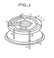
- FIG. 3 represents a view of a blade according to the invention fixed on its base, a figure in which the same elements as those of the preceding figures bear the same references.
- the blade is that shown diagrammatically in FIG. 1.
- the electrically conductive posts also having a holding function 15 and 17 pass through the base 42 respectively through an insulating glass bead 41, 40 and are extended externally by conductive posts 43 and 44 intended to be connected to the user circuits.
- the two holding bridges 16 and 18 are integral with the base 42 without electrical insulation.
Landscapes
- Physics & Mathematics (AREA)
- Acoustics & Sound (AREA)
- General Physics & Mathematics (AREA)
- Piezo-Electric Or Mechanical Vibrators, Or Delay Or Filter Circuits (AREA)
Applications Claiming Priority (2)
| Application Number | Priority Date | Filing Date | Title |
|---|---|---|---|
| FR8315654A FR2552953B1 (fr) | 1983-09-30 | 1983-09-30 | Resonateur piezo-electrique pour environnement severe |
| FR8315654 | 1983-09-30 |
Publications (2)
| Publication Number | Publication Date |
|---|---|
| EP0143680A1 true EP0143680A1 (de) | 1985-06-05 |
| EP0143680B1 EP0143680B1 (de) | 1987-06-24 |
Family
ID=9292726
Family Applications (1)
| Application Number | Title | Priority Date | Filing Date |
|---|---|---|---|
| EP19840401917 Expired EP0143680B1 (de) | 1983-09-30 | 1984-09-26 | Piezoelektrischer Resonator für schwierige Arbeitsbedingungen |
Country Status (4)
| Country | Link |
|---|---|
| EP (1) | EP0143680B1 (de) |
| JP (1) | JPS60178712A (de) |
| DE (1) | DE3464447D1 (de) |
| FR (1) | FR2552953B1 (de) |
Families Citing this family (1)
| Publication number | Priority date | Publication date | Assignee | Title |
|---|---|---|---|---|
| JPH0377526U (de) * | 1989-11-30 | 1991-08-05 |
Citations (3)
| Publication number | Priority date | Publication date | Assignee | Title |
|---|---|---|---|---|
| US3263103A (en) * | 1963-01-03 | 1966-07-26 | Bell Telephone Labor Inc | Radiation insensitive quartz crystal devices |
| FR2415914A1 (fr) * | 1978-01-27 | 1979-08-24 | France Etat | Resonateur piezoelectrique a cristal autosuspendu |
| US4375604A (en) * | 1981-02-27 | 1983-03-01 | The United States Of America As Represented By The Secretary Of The Army | Method of angle correcting doubly rotated crystal resonators |
Family Cites Families (3)
| Publication number | Priority date | Publication date | Assignee | Title |
|---|---|---|---|---|
| JPS4940494A (de) * | 1972-08-18 | 1974-04-16 | ||
| DE2356304A1 (de) * | 1973-11-10 | 1975-05-15 | Ibm Deutschland | Verfahren zur gewinnung von fehleranalysedaten |
| JPS50159988A (de) * | 1974-06-16 | 1975-12-24 |
-
1983
- 1983-09-30 FR FR8315654A patent/FR2552953B1/fr not_active Expired
-
1984
- 1984-09-26 EP EP19840401917 patent/EP0143680B1/de not_active Expired
- 1984-09-26 DE DE8484401917T patent/DE3464447D1/de not_active Expired
- 1984-09-28 JP JP20213984A patent/JPS60178712A/ja active Pending
Patent Citations (3)
| Publication number | Priority date | Publication date | Assignee | Title |
|---|---|---|---|---|
| US3263103A (en) * | 1963-01-03 | 1966-07-26 | Bell Telephone Labor Inc | Radiation insensitive quartz crystal devices |
| FR2415914A1 (fr) * | 1978-01-27 | 1979-08-24 | France Etat | Resonateur piezoelectrique a cristal autosuspendu |
| US4375604A (en) * | 1981-02-27 | 1983-03-01 | The United States Of America As Represented By The Secretary Of The Army | Method of angle correcting doubly rotated crystal resonators |
Also Published As
| Publication number | Publication date |
|---|---|
| FR2552953A1 (fr) | 1985-04-05 |
| FR2552953B1 (fr) | 1988-03-25 |
| JPS60178712A (ja) | 1985-09-12 |
| DE3464447D1 (en) | 1987-07-30 |
| EP0143680B1 (de) | 1987-06-24 |
Similar Documents
| Publication | Publication Date | Title |
|---|---|---|
| US4135108A (en) | Quartz resonator with electrodes that do not adhere to the crystal | |
| EP0010046A1 (de) | Piezoelektrischer Resonator | |
| EP0086739B1 (de) | Einbaufähiger piezoelektrischer Resonator | |
| JP5193051B2 (ja) | 電気音響素子 | |
| US8258895B2 (en) | Electroacoustic component | |
| FR2484735A1 (fr) | Resonateur a ondes acoustiques de surface | |
| EP1053593B1 (de) | Resonatorfilter mit akustischen oberflächenwellen | |
| FR2493984A1 (fr) | Transducteur de pression a element vibrant | |
| EP2306641A2 (de) | Herstellungsverfahren eines BAW-Resonators mit hohem Qualitätsfaktor | |
| FR2556165A1 (fr) | Reseau d'hydrophones en polymere a couches multiples | |
| EP1500191B1 (de) | Bauelement mit grenzflächenschallwellen aus lithiumtantalat | |
| EP0165158A1 (de) | Dielektrischer Filter mit veränderbarer Mittenfrequenz | |
| EP0143680B1 (de) | Piezoelektrischer Resonator für schwierige Arbeitsbedingungen | |
| EP0545809A1 (de) | Vorrichtung zum Montieren von breitbandigen monolitisch integrierten Mikrowellenschaltungen | |
| FR2656929A1 (fr) | Accelerometre differentiel a resonateurs piezoelectriques. | |
| EP0041297A1 (de) | Pyroelektrischer Detektor | |
| EP0056783B1 (de) | Piezoelektrischer Mikroresonator | |
| EP0350443B1 (de) | Piezoelektrischer Resonator | |
| EP0099779B1 (de) | Rauscharmer Oszillator für den Höchstfrequenzbereich | |
| EP0694824B1 (de) | Uhrwerk mit elektroakustischem Umsetzer | |
| EP0136943B1 (de) | Resonator mit niedriger Empfindlichkeit für Beschleunigungen | |
| US3562764A (en) | Annular type ceramic filter device | |
| FR2664750A1 (fr) | Bireflecteur a grilles. | |
| EP0451089B1 (de) | Hochfrequenter piezoelektrischer Schwinger | |
| EP0136942B1 (de) | Selbstaufgehängter Resonator mit hohem Gütefaktor |
Legal Events
| Date | Code | Title | Description |
|---|---|---|---|
| PUAI | Public reference made under article 153(3) epc to a published international application that has entered the european phase |
Free format text: ORIGINAL CODE: 0009012 |
|
| AK | Designated contracting states |
Designated state(s): BE CH DE GB IT LI LU NL SE |
|
| 17P | Request for examination filed |
Effective date: 19850727 |
|
| 17Q | First examination report despatched |
Effective date: 19860902 |
|
| GRAA | (expected) grant |
Free format text: ORIGINAL CODE: 0009210 |
|
| AK | Designated contracting states |
Kind code of ref document: B1 Designated state(s): BE CH DE GB IT LI LU NL SE |
|
| ITF | It: translation for a ep patent filed | ||
| REF | Corresponds to: |
Ref document number: 3464447 Country of ref document: DE Date of ref document: 19870730 |
|
| PG25 | Lapsed in a contracting state [announced via postgrant information from national office to epo] |
Ref country code: LU Free format text: LAPSE BECAUSE OF NON-PAYMENT OF DUE FEES Effective date: 19870930 |
|
| PGFP | Annual fee paid to national office [announced via postgrant information from national office to epo] |
Ref country code: NL Payment date: 19870930 Year of fee payment: 4 |
|
| PLBE | No opposition filed within time limit |
Free format text: ORIGINAL CODE: 0009261 |
|
| STAA | Information on the status of an ep patent application or granted ep patent |
Free format text: STATUS: NO OPPOSITION FILED WITHIN TIME LIMIT |
|
| 26N | No opposition filed | ||
| PG25 | Lapsed in a contracting state [announced via postgrant information from national office to epo] |
Ref country code: GB Effective date: 19890926 |
|
| PG25 | Lapsed in a contracting state [announced via postgrant information from national office to epo] |
Ref country code: SE Effective date: 19890927 |
|
| PG25 | Lapsed in a contracting state [announced via postgrant information from national office to epo] |
Ref country code: LI Effective date: 19890930 Ref country code: CH Effective date: 19890930 Ref country code: BE Effective date: 19890930 |
|
| BERE | Be: lapsed |
Owner name: CIE D'ELECTRONIQUE ET DE PIEZO-ELECTRICITE - C.E Effective date: 19890930 |
|
| PG25 | Lapsed in a contracting state [announced via postgrant information from national office to epo] |
Ref country code: NL Effective date: 19900401 |
|
| NLV4 | Nl: lapsed or anulled due to non-payment of the annual fee | ||
| GBPC | Gb: european patent ceased through non-payment of renewal fee | ||
| REG | Reference to a national code |
Ref country code: CH Ref legal event code: PL |
|
| PG25 | Lapsed in a contracting state [announced via postgrant information from national office to epo] |
Ref country code: DE Effective date: 19900601 |
|
| EUG | Se: european patent has lapsed |
Ref document number: 84401917.4 Effective date: 19900521 |