EP0143681A1 - Verfahren und Vorrichtung zur Kontrolle der Funktionstüchtigkeit einer Kabelbahn-Transport-Installation - Google Patents
Verfahren und Vorrichtung zur Kontrolle der Funktionstüchtigkeit einer Kabelbahn-Transport-Installation Download PDFInfo
- Publication number
- EP0143681A1 EP0143681A1 EP84401921A EP84401921A EP0143681A1 EP 0143681 A1 EP0143681 A1 EP 0143681A1 EP 84401921 A EP84401921 A EP 84401921A EP 84401921 A EP84401921 A EP 84401921A EP 0143681 A1 EP0143681 A1 EP 0143681A1
- Authority
- EP
- European Patent Office
- Prior art keywords
- line
- cable
- power
- signal
- normal
- Prior art date
- Legal status (The legal status is an assumption and is not a legal conclusion. Google has not performed a legal analysis and makes no representation as to the accuracy of the status listed.)
- Granted
Links
- 238000009434 installation Methods 0.000 title claims abstract description 28
- 238000000034 method Methods 0.000 title claims abstract description 10
- 238000012545 processing Methods 0.000 claims abstract description 5
- 230000006870 function Effects 0.000 claims description 8
- 238000006073 displacement reaction Methods 0.000 claims description 6
- 238000011156 evaluation Methods 0.000 claims description 3
- 238000005259 measurement Methods 0.000 claims description 3
- 238000005303 weighing Methods 0.000 claims description 3
- 235000003434 Sesamum indicum Nutrition 0.000 description 2
- 244000000231 Sesamum indicum Species 0.000 description 2
- 230000002159 abnormal effect Effects 0.000 description 1
- 230000005540 biological transmission Effects 0.000 description 1
- 238000012937 correction Methods 0.000 description 1
- 238000001514 detection method Methods 0.000 description 1
- 230000003449 preventive effect Effects 0.000 description 1
- 230000035945 sensitivity Effects 0.000 description 1
- 230000011664 signaling Effects 0.000 description 1
- 238000012546 transfer Methods 0.000 description 1
Images

Classifications
-
- B—PERFORMING OPERATIONS; TRANSPORTING
- B61—RAILWAYS
- B61B—RAILWAY SYSTEMS; EQUIPMENT THEREFOR NOT OTHERWISE PROVIDED FOR
- B61B12/00—Component parts, details or accessories not provided for in groups B61B7/00 - B61B11/00
- B61B12/06—Safety devices or measures against cable fracture
Definitions
- the invention relates to a method and a device for controlling the operating condition of an overhead cable transport installation driven by an electric motor and capable of transporting vehicles of variable load along a line of transportation. displacement extending between two stations, in which installation the instantaneous power of cable drive is measured and reduced by a signal.
- the tractor or carrier-tractor cable is driven by a power station and the movement is transmitted by the cable over a trajectory of several hundred meters or even over kilometers of which surveillance over the entire route is practically impossible.
- User safety nevertheless requires instant detection of any incident at any point in the installation, and detectors are known for cable derailment or untimely movement of the cable tension counterweight.
- the derailment detectors must be placed in line with each cable guide pulley and be connected by an electrical safety line extending along the installation, while the operation of the detector associated with the counterweight is unreliable.
- the present invention aims to remedy these inconveniences. come by carrying out a permanent control of the operation of the installation. It starts from the observation that the driving power of the cable at a given time is a function of the speed of the cable, the slope of the cable at the location of the vehicle (s) along the line, the load carried by the or vehicles and the condition of the facility. By determining the first three parameters, it is therefore possible to check the operating status of the installation.
- the method according to the invention is characterized in that the line data is recorded in a memory unit for the evaluation of the normal drive power of the cable as a function of the value of the load transported, of the position of the line vehicles and cable speed, which is provided to a central processing unit for data on cable drive speed, line vehicle load value and position of line vehicles at each instant, said central unit interrogating the memory unit to generate from said data a signal representative of said normal power and that said normal power and instantaneous power signals are continuously compared in a comparison block to develop a representative output signal the difference between said powers, said output signal triggering an alarm and / or a device for stopping the installation when a predetermined threshold is crossed completed.
- the position of the vehicle is given by the movement of the winch of the towing cable and it suffices to record the profile of the line and read this recording during the movement of the vehicle to have the data of calculation of normal power, if care is taken to count or weigh the passengers on board.
- the memory unit and the central processing unit can be very simple and produced by any suitable means. If the cable car has two skips, calculate the normal power for each skip and deduct the resulting total normal power.
- the control device receives the starting information at each clutch of a cabin in one or the other of the stations, at the same time as the information of the load. transported.
- the control device is advantageously in this case a computer, which tracks each cabin during its online movement and knowing at all times the different positions of the cabins, their loads, the speed of the gondola and the profile of the line, can calculate or determine the normal drive power of the cable.
- a simple comparator for example a differential amplifier and a threshold circuit, allows signaling of a notable difference between instantaneous and normal powers. Abnormal advancement resistance can thus be detected before the incident or accident and allows preventive intervention.
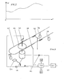
- a cable car comprises a motor 10 for driving the winch of the towing cable 12 of a bucket 14 circulating between the two stations A and B.
- a scale 16 weighs the passengers embarking in the bucket 14 and provides a signal P of the total weight of the bucket 14 to a central processing unit 18 of a control device designated by the general reference 20.
- a tachometer generator 22 coupled to the motor 10 supplies this central unit 18 with a signal V of the speed of the cable 12.
- the motor 10 drives by a transmission 24 a magnetic recording tape 26 with read heads 28, 30.
- the tape 26 moves in synchronism with the bucket 14 and the read heads 28, 30 read the recorded information corresponding to the location of the bucket online.
- One of the recording tracks of the tape 26 can represent the profile of the line, in this case the abscissas and ordinates of the ends of the staff, while the other track can represent correction factors, in particular at the start and braking of the bucket, as well as an increase in friction when passing a pylon.
- the central unit 18 permanently has the stored information read by the heads 28, 30 and the speed and load information and this data is transmitted to a calculation unit 32 which determines the normal drive power of the cable 12.
- the signal of calculated normal power is supplied to a comparator 34 which receives an instantaneous power signal emitted by a measuring device 36 of the electric power W supplied to the motor 10.
- the comparator 34 indicates the difference between these two powers and triggers an alarm or stops the installation if this difference exceeds a predetermined threshold.
- the device control can be simplified if the load transported is substantially constant and if the installation operates at one or two predetermined speeds. It is then possible to store directly on the tape 26 the normal drive power for each of the speeds and to read the information corresponding to the selected speed, the control device being limited to the comparator 34. It is clear that the speed signal can be calculated by the central unit, which may include a clock, on the basis of a movement signal of the strip 26 and that the load of the cabin can be determined in a different way.
- FIG. 2 shows an example of variation of the power as a function of the location of the bucket 14 on the line.
- the power difference can be permanent or at a given location which makes it possible to locate the anomaly.
- a scale (not shown) at the station B supplies the load signal P and the control device 20 receives slope change information.
- the cabins 38 are disengaged from the carrier-tractor cable 40 in the stations and run on transfer rails 42. At the outlet, the cabins 38 are engaged on the cable 40, which is permanently driven by a driving pulley 44 coupled to a motor. electric 46.
- the clutch of a cabin 38 is signaled by a through contact 48, which sends a start signal to a central unit 50 of a control computer 52.
- a scale 54 weighs the people embarking in the cabin and the corresponding signal P is transmitted to the central unit 50.
- This unit 50 also receives a displacement signal emitted by a pulse wheel 56 coupled to the driving pulley 44.
- the computer 52 includes a memory 58 in which are recorded the characteristics of the line, in particular the online profile and a unit of calculation 60, the time base being provided by a clock.
- the computer 52 emits a normal power signal transmitted to a comparator 62, which compares this signal with an instantaneous power signal W supplied by a Wattmeter 64 for measuring the electric power W supplying the motor 46.
Landscapes
- Engineering & Computer Science (AREA)
- Transportation (AREA)
- Mechanical Engineering (AREA)
- Electric Propulsion And Braking For Vehicles (AREA)
- Control Of Conveyors (AREA)
- Electric Cable Installation (AREA)
- Pipeline Systems (AREA)
- Sampling And Sample Adjustment (AREA)
- Control Of Position, Course, Altitude, Or Attitude Of Moving Bodies (AREA)
- Replacing, Conveying, And Pick-Finding For Filamentary Materials (AREA)
Priority Applications (1)
| Application Number | Priority Date | Filing Date | Title |
|---|---|---|---|
| AT84401921T ATE28155T1 (de) | 1983-10-03 | 1984-09-26 | Verfahren und vorrichtung zur kontrolle der funktionstuechtigkeit einer kabelbahn-transportinstallation. |
Applications Claiming Priority (2)
| Application Number | Priority Date | Filing Date | Title |
|---|---|---|---|
| FR8315839 | 1983-10-03 | ||
| FR8315839A FR2552725B1 (fr) | 1983-10-03 | 1983-10-03 | Procede et dispositif de controle du bon fonctionnement d'une installation de transport a cable aerien |
Publications (2)
| Publication Number | Publication Date |
|---|---|
| EP0143681A1 true EP0143681A1 (de) | 1985-06-05 |
| EP0143681B1 EP0143681B1 (de) | 1987-07-08 |
Family
ID=9292833
Family Applications (1)
| Application Number | Title | Priority Date | Filing Date |
|---|---|---|---|
| EP84401921A Expired EP0143681B1 (de) | 1983-10-03 | 1984-09-26 | Verfahren und Vorrichtung zur Kontrolle der Funktionstüchtigkeit einer Kabelbahn-Transport-Installation |
Country Status (5)
| Country | Link |
|---|---|
| EP (1) | EP0143681B1 (de) |
| JP (1) | JPS60110561A (de) |
| AT (1) | ATE28155T1 (de) |
| DE (1) | DE3464567D1 (de) |
| FR (1) | FR2552725B1 (de) |
Cited By (2)
| Publication number | Priority date | Publication date | Assignee | Title |
|---|---|---|---|---|
| FR2890929A1 (fr) * | 2005-09-21 | 2007-03-23 | Telepheriques Tarentaise Mauri | Procede et dispositif de controle d'un organe de freinage ou de mise en mouvement auxiliaire pour installation de transport a cable |
| CN103057547A (zh) * | 2012-12-19 | 2013-04-24 | 山东省科学院自动化研究所 | 往复式索道钢绳缠绕故障检测方法及装置 |
Families Citing this family (5)
| Publication number | Priority date | Publication date | Assignee | Title |
|---|---|---|---|---|
| FR2665131B1 (fr) * | 1990-07-27 | 1995-01-13 | Reel Sa | Installation de transfert par cable comportant des moyens permettant de controler la tension et l'adherence du cable tracteur sur la poulie d'entrainement. |
| US5528219A (en) * | 1994-04-28 | 1996-06-18 | Konrad Doppelmayr & Sohn | Ropeway safety monitoring system |
| JP4831748B2 (ja) * | 2006-08-22 | 2011-12-07 | 株式会社アドバンテスト | 電子部品試験装置 |
| JP6989108B2 (ja) * | 2017-09-25 | 2022-01-05 | 日本ケーブル株式会社 | 索道の運行状況表示装置 |
| FR3108185B1 (fr) * | 2020-03-11 | 2022-03-25 | Bureau Des Etudes De Cables | Procédé de contrôle d’une installation de transport de véhicules par un câble à mouvement continu et dispositif configuré pour mettre en œuvre le procédé. |
Citations (2)
| Publication number | Priority date | Publication date | Assignee | Title |
|---|---|---|---|---|
| DE1937763A1 (de) * | 1969-07-25 | 1971-02-11 | Pohlig Heckel Bleichert | Geraet zur selbsttaetigen Schleppkraftpruefung an fahrenden Seilbahnwagen |
| FR2122809A5 (de) * | 1971-01-22 | 1972-09-01 | Pomagalski Sa |
-
1983
- 1983-10-03 FR FR8315839A patent/FR2552725B1/fr not_active Expired
-
1984
- 1984-09-26 EP EP84401921A patent/EP0143681B1/de not_active Expired
- 1984-09-26 DE DE8484401921T patent/DE3464567D1/de not_active Expired
- 1984-09-26 AT AT84401921T patent/ATE28155T1/de not_active IP Right Cessation
- 1984-10-02 JP JP59206971A patent/JPS60110561A/ja not_active Expired - Lifetime
Patent Citations (2)
| Publication number | Priority date | Publication date | Assignee | Title |
|---|---|---|---|---|
| DE1937763A1 (de) * | 1969-07-25 | 1971-02-11 | Pohlig Heckel Bleichert | Geraet zur selbsttaetigen Schleppkraftpruefung an fahrenden Seilbahnwagen |
| FR2122809A5 (de) * | 1971-01-22 | 1972-09-01 | Pomagalski Sa |
Cited By (3)
| Publication number | Priority date | Publication date | Assignee | Title |
|---|---|---|---|---|
| FR2890929A1 (fr) * | 2005-09-21 | 2007-03-23 | Telepheriques Tarentaise Mauri | Procede et dispositif de controle d'un organe de freinage ou de mise en mouvement auxiliaire pour installation de transport a cable |
| CN103057547A (zh) * | 2012-12-19 | 2013-04-24 | 山东省科学院自动化研究所 | 往复式索道钢绳缠绕故障检测方法及装置 |
| CN103057547B (zh) * | 2012-12-19 | 2015-06-03 | 山东省科学院自动化研究所 | 往复式索道钢绳缠绕故障检测方法及装置 |
Also Published As
| Publication number | Publication date |
|---|---|
| DE3464567D1 (en) | 1987-08-13 |
| ATE28155T1 (de) | 1987-07-15 |
| FR2552725B1 (fr) | 1986-09-19 |
| FR2552725A1 (fr) | 1985-04-05 |
| JPS60110561A (ja) | 1985-06-17 |
| EP0143681B1 (de) | 1987-07-08 |
Similar Documents
| Publication | Publication Date | Title |
|---|---|---|
| EP1642096B1 (de) | Verfahren und einrichtung zur schätzung der gesamtmasse eines kraftfahrzeugs | |
| US5109343A (en) | Method and apparatus for verification of rail braking distances | |
| CA2137306C (fr) | Procede et dispositif pour detecter un depassement des charges de dimensionnement d'un aeronef | |
| CN101397113B (zh) | 乘客传送设备的链条松弛量诊断装置以及诊断方法 | |
| EP0143681B1 (de) | Verfahren und Vorrichtung zur Kontrolle der Funktionstüchtigkeit einer Kabelbahn-Transport-Installation | |
| EP0664271A1 (de) | Vorrichtung und Verfahren zur Kollisionsverhinderung für Fahrzeuge auf gemeinsamen Schienen | |
| US2963575A (en) | Hot box detector alarm circuit | |
| FR2696435A1 (fr) | Système de commande pour grue à câble. | |
| JPH05193850A (ja) | エレベータ乗降人数判定方法 | |
| CN104176613A (zh) | 乘客输送机的异常诊断系统 | |
| EP0120813B1 (de) | Verfahren zum fortlaufenden Wiegen von verteilten Produkten und Apparat zur Durchführung des Verfahrens | |
| US4065975A (en) | Apparatus for measuring the slip of locomotive wheels and preventing sliding thereof | |
| EP0404606B1 (de) | Verfahren zur Herstellung eines Alarmsignals an Bord eines Luftfahrzeuges im Falle einer Abnormalität in der Startphase | |
| US20180172718A1 (en) | Optical standoff sensor | |
| EP2716516A1 (de) | Verfahren und System zur Kontrolle der Bewegung von mehreren Fahrzeugen in einer Seilbahnstation, insbesondere eines Sesselliftes oder einer Gondelbahn | |
| FR2602894A1 (fr) | Systeme de comptage de mobiles traversant dans les deux sens une voie unique, a l'aide de cellules photoelectriques de detection directe | |
| US3633412A (en) | Equipment for testing the brakes of automobiles | |
| FR2645482A1 (fr) | Dispositif de freinage de securite d'un funiculaire | |
| JPH0850695A (ja) | 旅行時間決定方法 | |
| EP2803550A1 (de) | Vorrichtung und Verfahren zur Regelung der Geschwindigkeit eines Transportgerätes | |
| EP2660122A1 (de) | Verfahren und System zum Sichern der Bewegung eines Schienenfahrzeugs, Steuereinheit für das Schienenfahrzeug, und ein solches Schienenfahrzeug | |
| US3235723A (en) | Hot-box detector alarm circuit | |
| SE520659C2 (sv) | Anordning och förfarande för att risknivåbestämma en risksituation | |
| JPH10297491A (ja) | 列車人身事故防止システム | |
| KR20210073231A (ko) | 컨베이어 시스템 및 그 제어 방법 |
Legal Events
| Date | Code | Title | Description |
|---|---|---|---|
| PUAI | Public reference made under article 153(3) epc to a published international application that has entered the european phase |
Free format text: ORIGINAL CODE: 0009012 |
|
| AK | Designated contracting states |
Designated state(s): AT CH DE IT LI SE |
|
| 17P | Request for examination filed |
Effective date: 19851122 |
|
| RAP1 | Party data changed (applicant data changed or rights of an application transferred) |
Owner name: POMAGALSKI S.A. |
|
| 17Q | First examination report despatched |
Effective date: 19860918 |
|
| ITF | It: translation for a ep patent filed | ||
| GRAA | (expected) grant |
Free format text: ORIGINAL CODE: 0009210 |
|
| AK | Designated contracting states |
Kind code of ref document: B1 Designated state(s): AT CH DE IT LI SE |
|
| REF | Corresponds to: |
Ref document number: 28155 Country of ref document: AT Date of ref document: 19870715 Kind code of ref document: T |
|
| REF | Corresponds to: |
Ref document number: 3464567 Country of ref document: DE Date of ref document: 19870813 |
|
| PLBE | No opposition filed within time limit |
Free format text: ORIGINAL CODE: 0009261 |
|
| STAA | Information on the status of an ep patent application or granted ep patent |
Free format text: STATUS: NO OPPOSITION FILED WITHIN TIME LIMIT |
|
| 26N | No opposition filed | ||
| PGFP | Annual fee paid to national office [announced via postgrant information from national office to epo] |
Ref country code: SE Payment date: 19900921 Year of fee payment: 7 |
|
| PGFP | Annual fee paid to national office [announced via postgrant information from national office to epo] |
Ref country code: DE Payment date: 19901031 Year of fee payment: 7 |
|
| PG25 | Lapsed in a contracting state [announced via postgrant information from national office to epo] |
Ref country code: SE Effective date: 19910927 |
|
| ITTA | It: last paid annual fee | ||
| PG25 | Lapsed in a contracting state [announced via postgrant information from national office to epo] |
Ref country code: DE Effective date: 19920602 |
|
| PGFP | Annual fee paid to national office [announced via postgrant information from national office to epo] |
Ref country code: AT Payment date: 19930909 Year of fee payment: 10 |
|
| PGFP | Annual fee paid to national office [announced via postgrant information from national office to epo] |
Ref country code: CH Payment date: 19930929 Year of fee payment: 10 |
|
| REG | Reference to a national code |
Ref country code: CH Ref legal event code: PVP Owner name: CREDIT LYONNAIS SA |
|
| PG25 | Lapsed in a contracting state [announced via postgrant information from national office to epo] |
Ref country code: AT Effective date: 19940926 |
|
| PG25 | Lapsed in a contracting state [announced via postgrant information from national office to epo] |
Ref country code: LI Effective date: 19940930 Ref country code: CH Effective date: 19940930 |
|
| EUG | Se: european patent has lapsed |
Ref document number: 84401921.6 Effective date: 19920408 |
|
| REG | Reference to a national code |
Ref country code: CH Ref legal event code: PL |