EP0143692B1 - Verfahren und Vorrichtung zur Überwachung und Steuerung des Füllens einer Folge von Behältern mit einem bestimmten Gewicht eines Produkts mit wechselndem volumetrischem Gewicht - Google Patents
Verfahren und Vorrichtung zur Überwachung und Steuerung des Füllens einer Folge von Behältern mit einem bestimmten Gewicht eines Produkts mit wechselndem volumetrischem Gewicht Download PDFInfo
- Publication number
- EP0143692B1 EP0143692B1 EP84402269A EP84402269A EP0143692B1 EP 0143692 B1 EP0143692 B1 EP 0143692B1 EP 84402269 A EP84402269 A EP 84402269A EP 84402269 A EP84402269 A EP 84402269A EP 0143692 B1 EP0143692 B1 EP 0143692B1
- Authority
- EP
- European Patent Office
- Prior art keywords
- filling
- receptacle
- controlling
- volumetric dispenser
- carrousel
- Prior art date
- Legal status (The legal status is an assumption and is not a legal conclusion. Google has not performed a legal analysis and makes no representation as to the accuracy of the status listed.)
- Expired
Links
- 238000000034 method Methods 0.000 title claims description 8
- 238000009434 installation Methods 0.000 claims description 18
- 238000012544 monitoring process Methods 0.000 claims description 11
- 238000012546 transfer Methods 0.000 claims description 7
- 230000002159 abnormal effect Effects 0.000 claims description 4
- 238000005303 weighing Methods 0.000 claims description 4
- 230000001419 dependent effect Effects 0.000 claims 1
- 238000004891 communication Methods 0.000 description 3
- 230000006835 compression Effects 0.000 description 3
- 238000007906 compression Methods 0.000 description 3
- 238000012986 modification Methods 0.000 description 2
- 230000004048 modification Effects 0.000 description 2
- 230000000630 rising effect Effects 0.000 description 2
- 101100110009 Caenorhabditis elegans asd-2 gene Proteins 0.000 description 1
- 230000001174 ascending effect Effects 0.000 description 1
- 230000000903 blocking effect Effects 0.000 description 1
- 230000001143 conditioned effect Effects 0.000 description 1
- 239000003814 drug Substances 0.000 description 1
- 229940079593 drug Drugs 0.000 description 1
- 230000000694 effects Effects 0.000 description 1
- 235000013305 food Nutrition 0.000 description 1
- 239000011521 glass Substances 0.000 description 1
- 230000005484 gravity Effects 0.000 description 1
- 239000007788 liquid Substances 0.000 description 1
- 210000000056 organ Anatomy 0.000 description 1
- 238000004806 packaging method and process Methods 0.000 description 1
- 235000011837 pasties Nutrition 0.000 description 1
- 239000003208 petroleum Substances 0.000 description 1
- -1 pharmaceutical Substances 0.000 description 1
- 238000007789 sealing Methods 0.000 description 1
- 239000000126 substance Substances 0.000 description 1
Images

Classifications
-
- B—PERFORMING OPERATIONS; TRANSPORTING
- B65—CONVEYING; PACKING; STORING; HANDLING THIN OR FILAMENTARY MATERIAL
- B65B—MACHINES, APPARATUS OR DEVICES FOR, OR METHODS OF, PACKAGING ARTICLES OR MATERIALS; UNPACKING
- B65B3/00—Packaging plastic material, semiliquids, liquids or mixed solids and liquids, in individual containers or receptacles, e.g. bags, sacks, boxes, cartons, cans, or jars
- B65B3/26—Methods or devices for controlling the quantity of the material fed or filled
Definitions
- the subject of the present invention is a method and a device for monitoring and controlling the chain filling of containers with a determined weight of product having a variable density.
- this minimum time of presence of the container on the scale can be increased if containers are used whose weight varies from one container to another, which is the case for glass containers in particular, because it is necessary to tare each container. (One could naturally get rid of the need to tare each container by overdosing the product to be packaged so as to cover the variation in the weight of the containers but this would find the disadvantages presented by filling installations with volumetric dosing).
- An object of the invention is to provide a method and a device making it possible to obtain very good dosing precision while filling at a high rate.
- a method for monitoring and controlling the filling of containers comprising the steps of: successively engaging empty containers in a filling installation comprising an element of the rotary carrousel type with several filling stations , to weigh each container while it is still empty, to fill each container while comparing its weight to a set value by means of a scale moving with each filling station, and to stop the filling by closing a dispensing orifice when the set value is reached (such a process is known from document EP-A-052 546) characterized in that filling is carried out according to the steps of filling a volumetric metering device associated with each station with a volume of product whose weight is slightly greater than the set value, and transfer the product from the volumetric dispenser to the container under the effect of a c ommand, the abnormal forces resulting from the closure of the dispensing orifice before the flow of the total volume of product initially introduced into the volumetric dispenser being absorbed by elastic means interposed between the control member and the volume
- a device for monitoring and controlling the filling of containers successively engaged in a filling installation comprising an element of the rotary carousel type with several filling stations, each filling station filling comprising filling means and a scale which moves with the station, the installation further comprising a calculation and storage device for taring a container, comparing the weight of the container with a set value during filling and control the stopping of filling by closing a dispensing orifice when the weight of the container contents reaches the set value (such a device is known from document EP-A-052 546), characterized in that the means to filling include a volumetric dispenser to receive a determined volume of product having a weight in excess of the set value on a first path of the carousel and transfer a part of this volume in a container on a second path of the carousel, the installation further comprising a control member for controlling the filling of each volumetric dispenser during the first journey of the carousel and
- Figure 1 are shown the different phases of the path of a container on a chain filling installation comprising a rotary carousel 3 equipped with several filling stations.
- the container is conveyed by a conveying means 1 to a distribution star 2 which introduces it at point 6 onto one of the filling stations of the carousel 3, which is driven in a rotational movement.
- a distribution star 2 which introduces it at point 6 onto one of the filling stations of the carousel 3, which is driven in a rotational movement.
- the container is tared, by resetting the balance to zero for example, while the filling of the volumetric metering device started at point 10 is completed.
- point 7 and point 8 part of the volume of product contained in the volumetric dispenser is transferred with a rapid flow from the dispenser into the container.
- the transfer continues with a slower flow until the container contains the desired weight of product.
- the container is weighed continuously.
- a calculation and storage unit a microprocessor for example, continuously compares the weight of the product contained in the container with the desired weight and, when this desired weight is reached, stops filling of the container.
- the filled container then leaves the carousel 3 or tangentially to the carousel 3, on a conveying means 25 or else in a preferred direction, parallel to a conveying means 1 for example, via a distribution star 4 on a conveying means 5.
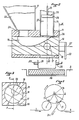
- FIG. 2 shows a schematic sectional view of an exemplary embodiment of a filling station.
- Each filling station is located on the rotary carousel 3 and comprises: an electronic balance 36; means 38 for centering a container 39; a hopper for supplying the product to be packaged 12; a volumetric metering device 37 comprising a piston 28 provided with sealing means 29, a cylinder 13 in which the piston 28 slides, a rod 33 actuating the piston 28; a distributor 14 comprising a body 19 and a cylindrical plug 18 capable of pivoting in the body 19.
- the body 19 has a horizontal bore of axis 27; a vertical duct 24 located in its upper part and opening on the one hand into the feed hopper 12 and on the other hand into the bore of axis 27; a vertical duct 26 located in its upper part and opening on the one hand into the volumetric metering device 37 and on the other hand into the bore of axis 27; a vertical bore of the same axis as the conduit 26, surmounting the latter and receiving the cylinder 13 of the volumetric metering device 37; a vertical duct 30 situated in its lower part and opening on the one hand into the bore of axis 27 and on the other hand above the container 39.
- the cylindrical plug 18 occupies the vertical bore of axis 27 of the body 19, in which it can pivot. It comprises a recess 15 which, in a determined position of the plug 18 relative to the body 19, connects the conduits 24 and 26 of the body 19; a cylindrical conduit 17, without communication with the recess 15, which, in another determined position of the plug 18 relative to the body 19, connects the conduits 26 and 30 of the body 19; a control lever 20 for pivoting the plug 18 inside the body 19. Electrical, pneumatic or equivalent means, not shown in the figure, act on the control lever 20 on the instructions that communicates to them the organ for calculation and storage.
- the plug 18 When a filling station is located between points 10 and 7 of the path shown in FIG. 1, the plug 18 is positioned so that the recess 15 faces the conduits 24 and 26 of the body 19 and the hopper of supply 12 and the volumetric dispenser 37 are in communication (case of FIG. 2). When a filling station is between point 7 and the filling stop point located between points 8 and 9 of the path shown in Figure 1, the plug 18 is positioned so that the conduit 17 is facing the conduits 26 and 30 of the body 19 and the votumetric dispenser 37 and the container 39 are in communication.
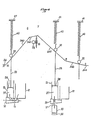
- FIG. 4 represents a schematic developed view of a cam controlling the operation of two filling stations. It must be understood that in reality such a cam is not located in a plane but is wound on a cylinder with the same center as the carousel and that it controls a number of filling stations, variable depending on the case, but well above 2.
- the cam 34 shown in FIG. 4 comprises a rising ramp with two successive inclinations: ramp 340 between points 10 and 6, ramp 341 between points 6 and 7; a downward ramp with two inclinations: ramp 342 between points 7 and 8, ramp 343 between points 8 and 9; a horizontal part 344 between points 9 and 10 (the numbering of these points corresponds to that of FIG. 1).
- the upward path corresponds to the filling of the volumetric dispenser 37.
- the downward path corresponds in part to the transfer of the product from the volumetric doser 37 into the container 39.
- the cam 34 is fixed relative to the rotary carousel 3 on which the filling stations are installed. It controls the operation of each of them by guiding a roller 32 secured to the rod 33 of the piston 28, by the interposition of elastic means 40 fixed on the one hand to the end of the rod 33, on the other hand to a fixed point 41 secured to the carousel.
- the elastic means 40 work in compression and keep the roller 32 in contact with the cam 34 which allows the guide of the roller 32 by the cam on the downward ramp thereof. They have another function: when the container 39 is filled with the desired weight of product, the calculation and storage unit controls the closing of the dispensing orifice of the volumetric dispenser. The stroke of the piston 28 is thereby interrupted.
- the roller 32 was guided along the downward ramp by rigid means, a rail parallel to the cam 34 coming into contact with the upper part of the roller, for example, damage would ensue.
- the elastic means 40 the compression force of which has been calculated so that it is greater than the resistance encountered by the piston of the volumetric dispenser when it drives the product into the container, but less than the resistant force exerted on the elastic means by the piston rod when it is blocked, absorb the excess travel of the piston.
- the roller 32 leaves the contact of the descending ramp of the cam at the point of stopping the filling of the container and resumes contact with the rising ramp of the cam at a point situated in the same horizontal plane as the point of stopping the filling of the container.
- the guiding of the roller 32 by the cam 34 with the interposition of elastic means also constitutes security for the filling installation: the accidental blocking of a piston does not cause any unfortunate consequence of the fact that the roller can escape from drug.
- the filling of the volumetric metering device 37 can be modified so that the point of stopping the filling of the container 39 takes place between points 8 and 9, that is to say on the descending ramp 343, when the filling rate is slow.
- FIG. 4 is shown a device, allowing the modification of the volume admitted into the volumetric metering device, constituted by a part of an ascending ramp 341 of the cam 34 with adjustable inclination, and a geared motor 25 actuating an endless screw 16.
- the inclination of the ramp part 341 is adjusted so that the point of stopping the filling of the containers takes place between points 8 and 9.
- the calculation and storage unit records the coordinates of the stop point for filling each container and check that it is on the ramp part 343. If for some reason or other a drift occurs and the stop point for filling the containers closer to point 8 or point 9 beyond determined set values, the calculation and storage unit would command a modification of the inclination of the ramp part 341, up or down depending on the sense of drift.
- FIG. 5 represents an exemplary embodiment of elastic means interposed between the cam 34 and the rod 33 of the piston of each volumetric metering device 37.
- the elastic means used in this example consist of a pneumatic cylinder comprising a cylinder 44 secured to the carousel 3, a piston 43 sliding in the cylinder 44, a rod 42 fixed to the piston 43 at one end and secured to the roller 32 at the other end.
- the pneumatic cylinder of each filling station is connected to the cylinder of all the other filling stations and to a buffer volume 46 by a pipe 45.
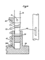
- Figure 6 shows the sectional view of another embodiment of elastic means interposed between the cam 34 and the rod 33 of the piston of each volumetric metering device.
- the piston 28 of the volumetric metering device 37 is surmounted by a cylindrical part 47 comprising a bore intended to guide the end of the rod 33.
- the rod 33 comprises a vertical slot 48. It enters the bore of the cylindrical part 47 where it can slide vertically between two extreme positions defined by light 48, light in which passes a horizontal pin 50 taken at its two ends in the cylindrical part 47.
- On the rod 33 is further fixed by a pin 51, a ring 49 having a shoulder.
- a spring 52 working in compression is disposed between the ring 49 and the piston 28 along the axis of the rod 33.
Landscapes
- Engineering & Computer Science (AREA)
- Mechanical Engineering (AREA)
- Basic Packing Technique (AREA)
- Weight Measurement For Supplying Or Discharging Of Specified Amounts Of Material (AREA)
- Filling Of Jars Or Cans And Processes For Cleaning And Sealing Jars (AREA)
- Supplying Of Containers To The Packaging Station (AREA)
- Processing And Handling Of Plastics And Other Materials For Molding In General (AREA)
- Auxiliary Devices For And Details Of Packaging Control (AREA)
- Container Filling Or Packaging Operations (AREA)
Claims (8)
Priority Applications (1)
| Application Number | Priority Date | Filing Date | Title |
|---|---|---|---|
| AT84402269T ATE33469T1 (de) | 1983-11-18 | 1984-11-09 | Verfahren und vorrichtung zur ueberwachung und steuerung des fuellens einer folge von behaeltern mit einem bestimmten gewicht eines produkts mit wechselndem volumetrischem gewicht. |
Applications Claiming Priority (2)
| Application Number | Priority Date | Filing Date | Title |
|---|---|---|---|
| FR8318417A FR2555132B1 (fr) | 1983-11-18 | 1983-11-18 | Procede de remplissage d'un recipient d'une quantite determinee de produit |
| FR8318417 | 1983-11-18 |
Publications (2)
| Publication Number | Publication Date |
|---|---|
| EP0143692A1 EP0143692A1 (de) | 1985-06-05 |
| EP0143692B1 true EP0143692B1 (de) | 1988-04-13 |
Family
ID=9294298
Family Applications (1)
| Application Number | Title | Priority Date | Filing Date |
|---|---|---|---|
| EP84402269A Expired EP0143692B1 (de) | 1983-11-18 | 1984-11-09 | Verfahren und Vorrichtung zur Überwachung und Steuerung des Füllens einer Folge von Behältern mit einem bestimmten Gewicht eines Produkts mit wechselndem volumetrischem Gewicht |
Country Status (10)
| Country | Link |
|---|---|
| US (1) | US4635688A (de) |
| EP (1) | EP0143692B1 (de) |
| JP (1) | JPH0627662B2 (de) |
| AT (1) | ATE33469T1 (de) |
| BR (1) | BR8405869A (de) |
| CA (1) | CA1232883A (de) |
| DE (1) | DE3470401D1 (de) |
| ES (1) | ES537739A0 (de) |
| FR (1) | FR2555132B1 (de) |
| ZA (1) | ZA848851B (de) |
Families Citing this family (9)
| Publication number | Priority date | Publication date | Assignee | Title |
|---|---|---|---|---|
| DE3630077A1 (de) * | 1986-09-04 | 1988-03-17 | Benz & Hilgers Gmbh | Vorrichtung zum gleichzeitigen dosierten abfuellen von fluessigen oder weichplastischen stoffen, wie butter, margarine, pasten oder dgl. ueber mundstuecke in benachbart zueinander angeordnete behaelter |
| US4817683A (en) * | 1987-07-01 | 1989-04-04 | Laub Engineering Corporation | Adjustable automatic accurate container filling machine |
| DE3938220A1 (de) * | 1989-11-17 | 1991-05-23 | Benz & Hilgers Gmbh | Verfahren und vorrichtung zum verpacken von pastoesen produkten, wie suppenpasten, margarine, butter oder dgl. in form von paeckchen, wuerfeln oder dgl. |
| DE4117287A1 (de) * | 1991-05-27 | 1992-12-03 | Seitz Enzinger Noll Masch | Verfahren zum fuellen von flaschen, dosen o. dgl. behaelter sowie fuellmaschine zum durchfuehren dieses verfahrens |
| US5280815A (en) * | 1992-05-05 | 1994-01-25 | Prc | Product filling machine |
| US5356041A (en) * | 1993-03-23 | 1994-10-18 | Fluid Management Limited Partnership | Dispensing apparatus having improved valving |
| IT1285580B1 (it) * | 1996-03-04 | 1998-06-18 | Mg 2 Spa | Metodo per il controllo del peso in macchine dosatrici e dosaggio multiplo di prodotti in granuli e macchina dosatrice che attua il |
| US5921759A (en) * | 1997-10-14 | 1999-07-13 | Sandeep Khan | Liquid metering piston pump and valves capable of being cleaned and sterilized without disassembly |
| DE10001068C1 (de) * | 2000-01-13 | 2001-05-31 | Bosch Gmbh Robert | Vorrichtung zum Dosieren und Abgeben von Pulver in Hartgelatinekapseln oder dergleichen |
Citations (1)
| Publication number | Priority date | Publication date | Assignee | Title |
|---|---|---|---|---|
| EP0052546A2 (de) * | 1980-11-13 | 1982-05-26 | S.E.R.A.C. Group | Verfahren und Vorrichtung zum portionsweisen Abfüllen von Materialien in einer Füllmaschine mit Gewichtsbestimmung |
Family Cites Families (15)
| Publication number | Priority date | Publication date | Assignee | Title |
|---|---|---|---|---|
| US1726297A (en) * | 1923-04-23 | 1929-08-27 | Hansen Canning Machinery Corp | Apparatus for treating kraut |
| US2280614A (en) * | 1939-01-17 | 1942-04-21 | Harry D Ayars | Filling machine |
| US2321994A (en) * | 1939-12-11 | 1943-06-15 | Frank D Chapman | Receptacle filler |
| US2925835A (en) * | 1958-03-31 | 1960-02-23 | Kartridg Pak Machine Co | Automatic filling and weight checking machine |
| US2961013A (en) * | 1958-04-28 | 1960-11-22 | Texaco Inc | Positive displacement type fluid filling machine having automatic cam track adjustingmeans and method of filling |
| US3189062A (en) * | 1961-07-26 | 1965-06-15 | Cherry Burrell Corp | Filling machine |
| US3240146A (en) * | 1962-11-20 | 1966-03-15 | Swift & Co | Controls for ham pumping |
| GB1023469A (en) * | 1962-12-13 | 1966-03-23 | Holstein & Kappert Maschf | Apparatus for controlling pumps for filling containers with liquid |
| FR1563577A (de) * | 1967-06-14 | 1969-04-11 | ||
| CH570932A5 (de) * | 1973-10-10 | 1975-12-31 | Rieter Ag Maschf | |
| US4060109A (en) * | 1976-05-14 | 1977-11-29 | Kewpie Kabushiki Kaisha | Filling quantity regulating system in container filling apparatus |
| US4060106A (en) * | 1976-05-21 | 1977-11-29 | Kewpie Kabushiki Kaisha | Method and system for preventing containerless discharging of filling material in container filling apparatus |
| US4244404A (en) * | 1979-02-12 | 1981-01-13 | Domain Industries, Inc. | Rotary piston filler |
| JPS56113528A (en) * | 1980-02-05 | 1981-09-07 | Dainippon Printing Co Ltd | Germless filling method |
| US4337802A (en) * | 1980-09-30 | 1982-07-06 | Velasco Scale Company, Inc. | Method and apparatus for liquid filling of containers |
-
1983
- 1983-11-18 FR FR8318417A patent/FR2555132B1/fr not_active Expired
-
1984
- 1984-11-09 DE DE8484402269T patent/DE3470401D1/de not_active Expired
- 1984-11-09 EP EP84402269A patent/EP0143692B1/de not_active Expired
- 1984-11-09 AT AT84402269T patent/ATE33469T1/de not_active IP Right Cessation
- 1984-11-13 ZA ZA848851A patent/ZA848851B/xx unknown
- 1984-11-15 US US06/671,667 patent/US4635688A/en not_active Expired - Fee Related
- 1984-11-16 ES ES537739A patent/ES537739A0/es active Granted
- 1984-11-16 BR BR8405869A patent/BR8405869A/pt not_active IP Right Cessation
- 1984-11-16 CA CA000468079A patent/CA1232883A/en not_active Expired
- 1984-11-17 JP JP59243140A patent/JPH0627662B2/ja not_active Expired - Lifetime
Patent Citations (1)
| Publication number | Priority date | Publication date | Assignee | Title |
|---|---|---|---|---|
| EP0052546A2 (de) * | 1980-11-13 | 1982-05-26 | S.E.R.A.C. Group | Verfahren und Vorrichtung zum portionsweisen Abfüllen von Materialien in einer Füllmaschine mit Gewichtsbestimmung |
Also Published As
| Publication number | Publication date |
|---|---|
| FR2555132A1 (fr) | 1985-05-24 |
| CA1232883A (en) | 1988-02-16 |
| ATE33469T1 (de) | 1988-04-15 |
| FR2555132B1 (fr) | 1986-03-28 |
| ZA848851B (en) | 1985-06-26 |
| EP0143692A1 (de) | 1985-06-05 |
| ES8601046A1 (es) | 1985-10-16 |
| BR8405869A (pt) | 1985-09-17 |
| JPS60155927A (ja) | 1985-08-16 |
| ES537739A0 (es) | 1985-10-16 |
| US4635688A (en) | 1987-01-13 |
| DE3470401D1 (en) | 1988-05-19 |
| JPH0627662B2 (ja) | 1994-04-13 |
Similar Documents
| Publication | Publication Date | Title |
|---|---|---|
| EP0500831B1 (de) | Verfahren und vorrichtung zur einstellung von produktmengen, dosiert und verteilt mittels eines dosierspenders | |
| EP0143692B1 (de) | Verfahren und Vorrichtung zur Überwachung und Steuerung des Füllens einer Folge von Behältern mit einem bestimmten Gewicht eines Produkts mit wechselndem volumetrischem Gewicht | |
| US4084626A (en) | Automatically operational net weight filling machine | |
| EP0001196A1 (de) | Vorrichtung zur automatischen Kontrolle einer Abfüllmaschine für Behälter | |
| EP0147263B1 (de) | Verfahren und Vorrichtung zur Überwachung und Steuerung des Füllens von Behältern mit einem bestimmten Gewicht eines Produkts | |
| US3578778A (en) | Packaging apparatus for filling individual containers | |
| FR2491050A1 (fr) | Procede de commande de dispositifs de remplissage de machines de remplissage, equipes de soupapes a liquide actionnables electriquement, et montage pour la mise en oeuvre de ce procede | |
| FR2615496A1 (fr) | Dispositif de stockage d'objets | |
| FR2748463A1 (fr) | Installation de remplissage et de bouchage de recipients destines a contenir des produits liquides ou pateux | |
| KR101446100B1 (ko) | 캡핑기 | |
| US2107274A (en) | Filling machine | |
| CA1110195A (en) | Bottle orientation unit | |
| FR2574753A1 (fr) | Procede et machine de remplissage et de bouchage de flacons | |
| US3095055A (en) | Automatic filling and weighing device for successive containers | |
| EP0120778A1 (de) | Verfahren und Vorrichtung zum Füllen eines Behälters | |
| EP0537094A1 (de) | Elektronischer Verfahren und Anlage zum Abfüllen Flüssiggasflaschen | |
| FR2607122A1 (fr) | Ligne d'acheminement de pieces pour une distribution orientee de ces dernieres | |
| EP0360687A1 (de) | Automatisches System zum Füllen von Behältern mit länglichen Gegenständen wie grünen Bohnen | |
| EP3448789A1 (de) | Vorrichtung zur geregelten verteilung von komponenten | |
| EP2786102B1 (de) | Vorrichtung zur abgabe eines pulvers, kappe für eine solche vorrichtung und arbeitsplatz mit einer derartigen vorrichtung | |
| FR2683295A1 (fr) | Appareil de pose automatique d'un joint dans le nez de robinet d'une bouteille de gaz. | |
| FR2794856A1 (fr) | Procede de dosage a haute precision de quantites de produit pulverulent ou granulaire et dispositif pour sa mise en oeuvre | |
| FR2650558A1 (fr) | Ensemble pour l'alimentation automatique d'une ligne d'embouteillage de recipients | |
| SU1018879A1 (ru) | Устройство дл съема клапанных мешков с патрубка расфасовочной машины | |
| US3032946A (en) | Continuous packaging and packageranging unit |
Legal Events
| Date | Code | Title | Description |
|---|---|---|---|
| PUAI | Public reference made under article 153(3) epc to a published international application that has entered the european phase |
Free format text: ORIGINAL CODE: 0009012 |
|
| AK | Designated contracting states |
Designated state(s): AT BE CH DE FR GB IT LI LU NL SE |
|
| 17P | Request for examination filed |
Effective date: 19851122 |
|
| 17Q | First examination report despatched |
Effective date: 19860825 |
|
| D17Q | First examination report despatched (deleted) | ||
| ITF | It: translation for a ep patent filed | ||
| GRAA | (expected) grant |
Free format text: ORIGINAL CODE: 0009210 |
|
| AK | Designated contracting states |
Kind code of ref document: B1 Designated state(s): AT BE CH DE FR GB IT LI LU NL SE |
|
| REF | Corresponds to: |
Ref document number: 33469 Country of ref document: AT Date of ref document: 19880415 Kind code of ref document: T |
|
| GBT | Gb: translation of ep patent filed (gb section 77(6)(a)/1977) | ||
| REF | Corresponds to: |
Ref document number: 3470401 Country of ref document: DE Date of ref document: 19880519 |
|
| PLBE | No opposition filed within time limit |
Free format text: ORIGINAL CODE: 0009261 |
|
| STAA | Information on the status of an ep patent application or granted ep patent |
Free format text: STATUS: NO OPPOSITION FILED WITHIN TIME LIMIT |
|
| 26N | No opposition filed | ||
| ITTA | It: last paid annual fee | ||
| PGFP | Annual fee paid to national office [announced via postgrant information from national office to epo] |
Ref country code: GB Payment date: 19921105 Year of fee payment: 9 |
|
| PGFP | Annual fee paid to national office [announced via postgrant information from national office to epo] |
Ref country code: FR Payment date: 19921106 Year of fee payment: 9 Ref country code: CH Payment date: 19921106 Year of fee payment: 9 |
|
| PGFP | Annual fee paid to national office [announced via postgrant information from national office to epo] |
Ref country code: LU Payment date: 19921111 Year of fee payment: 9 |
|
| PGFP | Annual fee paid to national office [announced via postgrant information from national office to epo] |
Ref country code: SE Payment date: 19921117 Year of fee payment: 9 |
|
| PGFP | Annual fee paid to national office [announced via postgrant information from national office to epo] |
Ref country code: NL Payment date: 19921130 Year of fee payment: 9 Ref country code: BE Payment date: 19921130 Year of fee payment: 9 Ref country code: AT Payment date: 19921130 Year of fee payment: 9 |
|
| PGFP | Annual fee paid to national office [announced via postgrant information from national office to epo] |
Ref country code: DE Payment date: 19921215 Year of fee payment: 9 |
|
| EPTA | Lu: last paid annual fee | ||
| PG25 | Lapsed in a contracting state [announced via postgrant information from national office to epo] |
Ref country code: LU Free format text: LAPSE BECAUSE OF NON-PAYMENT OF DUE FEES Effective date: 19931109 Ref country code: GB Effective date: 19931109 Ref country code: AT Effective date: 19931109 |
|
| PG25 | Lapsed in a contracting state [announced via postgrant information from national office to epo] |
Ref country code: SE Effective date: 19931110 |
|
| PG25 | Lapsed in a contracting state [announced via postgrant information from national office to epo] |
Ref country code: LI Effective date: 19931130 Ref country code: CH Effective date: 19931130 Ref country code: BE Effective date: 19931130 |
|
| BERE | Be: lapsed |
Owner name: ETS A. BERTAUD Effective date: 19931130 |
|
| PG25 | Lapsed in a contracting state [announced via postgrant information from national office to epo] |
Ref country code: NL Effective date: 19940601 |
|
| GBPC | Gb: european patent ceased through non-payment of renewal fee |
Effective date: 19931109 |
|
| NLV4 | Nl: lapsed or anulled due to non-payment of the annual fee | ||
| PG25 | Lapsed in a contracting state [announced via postgrant information from national office to epo] |
Ref country code: FR Effective date: 19940729 |
|
| REG | Reference to a national code |
Ref country code: CH Ref legal event code: PL |
|
| PG25 | Lapsed in a contracting state [announced via postgrant information from national office to epo] |
Ref country code: DE Effective date: 19940802 |
|
| REG | Reference to a national code |
Ref country code: FR Ref legal event code: ST |
|
| EUG | Se: european patent has lapsed |
Ref document number: 84402269.9 Effective date: 19940610 |