EP0143729A2 - Adjustable golf clubs for pushing the balls - Google Patents
Adjustable golf clubs for pushing the balls Download PDFInfo
- Publication number
- EP0143729A2 EP0143729A2 EP84430036A EP84430036A EP0143729A2 EP 0143729 A2 EP0143729 A2 EP 0143729A2 EP 84430036 A EP84430036 A EP 84430036A EP 84430036 A EP84430036 A EP 84430036A EP 0143729 A2 EP0143729 A2 EP 0143729A2
- Authority
- EP
- European Patent Office
- Prior art keywords
- blades
- head
- handle
- golf club
- rod
- Prior art date
- Legal status (The legal status is an assumption and is not a legal conclusion. Google has not performed a legal analysis and makes no representation as to the accuracy of the status listed.)
- Withdrawn
Links
Images
Classifications
-
- A—HUMAN NECESSITIES
- A63—SPORTS; GAMES; AMUSEMENTS
- A63B—APPARATUS FOR PHYSICAL TRAINING, GYMNASTICS, SWIMMING, CLIMBING, OR FENCING; BALL GAMES; TRAINING EQUIPMENT
- A63B69/00—Training appliances or apparatus for special sports
- A63B69/36—Training appliances or apparatus for special sports for golf
- A63B69/3623—Training appliances or apparatus for special sports for golf for driving
- A63B69/3632—Clubs or attachments on clubs, e.g. for measuring, aligning
-
- A—HUMAN NECESSITIES
- A63—SPORTS; GAMES; AMUSEMENTS
- A63B—APPARATUS FOR PHYSICAL TRAINING, GYMNASTICS, SWIMMING, CLIMBING, OR FENCING; BALL GAMES; TRAINING EQUIPMENT
- A63B53/00—Golf clubs
- A63B53/02—Joint structures between the head and the shaft
- A63B53/022—Joint structures between the head and the shaft allowing adjustable positioning of the head with respect to the shaft
-
- A—HUMAN NECESSITIES
- A63—SPORTS; GAMES; AMUSEMENTS
- A63B—APPARATUS FOR PHYSICAL TRAINING, GYMNASTICS, SWIMMING, CLIMBING, OR FENCING; BALL GAMES; TRAINING EQUIPMENT
- A63B53/00—Golf clubs
- A63B53/02—Joint structures between the head and the shaft
- A63B53/022—Joint structures between the head and the shaft allowing adjustable positioning of the head with respect to the shaft
- A63B53/023—Joint structures between the head and the shaft allowing adjustable positioning of the head with respect to the shaft adjustable angular orientation
-
- A—HUMAN NECESSITIES
- A63—SPORTS; GAMES; AMUSEMENTS
- A63B—APPARATUS FOR PHYSICAL TRAINING, GYMNASTICS, SWIMMING, CLIMBING, OR FENCING; BALL GAMES; TRAINING EQUIPMENT
- A63B53/00—Golf clubs
- A63B53/04—Heads
- A63B53/0416—Heads having an impact surface provided by a face insert
- A63B53/042—Heads having an impact surface provided by a face insert the face insert consisting of a material different from that of the head
- A63B53/0425—Heads having an impact surface provided by a face insert the face insert consisting of a material different from that of the head the face insert comprising two or more different materials
-
- A—HUMAN NECESSITIES
- A63—SPORTS; GAMES; AMUSEMENTS
- A63B—APPARATUS FOR PHYSICAL TRAINING, GYMNASTICS, SWIMMING, CLIMBING, OR FENCING; BALL GAMES; TRAINING EQUIPMENT
- A63B53/00—Golf clubs
- A63B53/04—Heads
- A63B53/06—Heads adjustable
- A63B53/065—Heads adjustable for putters
Definitions
- the subject of the invention is golf clubs or transformable clubs which are used to push the ball in order to make it roll over the ground in the direction of a hole which is at a relatively short distance, of the order of a few centimeters. a few tens of meters.
- An object of the present invention is to provide new golf clubs intended to push the balls towards the holes, which make it possible to vary the shape and the weight of the head and the angle formed by the handle and by the surface of head support.
- Another object of the invention is to provide golf clubs intended to push the balls towards the holes which include simple aiming devices which make it possible to improve the accuracy of the shots.
- Another object of the invention is to provide golf clubs to push the balls towards the holes which can be easily transformed to be adapted to different players or to the various stages of play of the same player.
- the objectives of the invention are achieved by means of transformable golf clubs, the head of which is made up of several blades parallel to the front face which are kept pressed against one another by screws.
- the two central blades each have a half-groove and the two half-grooves are placed opposite one another and they define a groove in which is engaged one end of an interchangeable connecting piece.
- a cane according to the invention comprises a folded plate, one part of which is arranged parallel to said blades and the other part of which, which is situated above said blades, is inclined towards the rear and has a reflective front face and carries a rectilinear mark which is perpendicular to the fold between the two half-plates.
- the front face of the head has one or two reflecting areas, each carrying a rectilinear mark which is perpendicular to the lower edge of the head.
- the invention results in new golf clubs of the "putter" type, which are easily transformable and adaptable to the playing conditions and the skills of the players.
- the head weight can easily be changed by adding additional blades or by replacing some blades with heavier blades. It is also possible to provide the head with a dorsal blade or rear blade, the shape of which can vary according to the use cases. For example, the head can be provided, depending on the circumstances, with back blades having various hoof shapes to facilitate guiding the head on the ground. Similarly, the head can be provided with intermediate T-shaped blades, the upper edge of which covers the upper edges of the front and back blades.
- the golf clubs according to the invention can be provided. easily of a sighting device which can be constituted for example by a plate which is pinched between two blades or applied against the rear face of the dorsal blade and which comprises a reflecting part situated above the head and inclined towards the backwards at an angle of 45 °, so that the player who is preparing to push the ball can see, in the reflecting face, the image of the stake which marks the position of the hole to be reached, which allows him to better target it without having to raise his head.
- a reflective face can be placed on the front face of the head which has the same advantages.
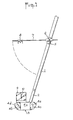
- Figure 1 shows a golf club used to push the ball into the holes.
- This rod is composed of a straight handle 1 which is fitted onto a connecting piece 2, which is fixed to a head 3.
- the head is seen from the side of the front face.
- the front face has, in its center, a smooth pad 4a which is used to strike the ball.
- This smooth area is placed between two reflecting areas 4b and 4c which act as a mirror.
- Each reflecting face carries a vertical mark 4d, 4th constituted by a line or a slit.
- a sleeve 5 is fixed to the handle 1.
- This sleeve carries an articulation 6 with a horizontal axis around which a rod 7 is articulated.
- the rod 7 is sliding. It carries a cursor 8 which is movable along the rod. By rotating the rod 7 around the articulation 6, it can be brought horizontally to the position shown in Figure 1 or fold against the handle.
- FIG. 1 a plate 9 having a reflective front face on which a vertical mark 10 is drawn. This plate 9 also serves as an aiming mirror.
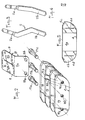
- Figure 2 is an exploded perspective view of the head, 3. It is composed of several vertical blades. For example, it has two central blades 11 and 12, a front blade 13 and a rear blade 14 whose upper and lower walls can have different shapes. These blades are parallel to the front face.
- the central blades 11 and 12 each have a half-groove 15a, 15b. These two half-grooves are located opposite one another and define a groove 15 in which the lower end of the connecting piece 2 is fitted. The axis of the groove 15 forms an obtuse angle with the lower edge of the blades.
- Each blade is pierced with several holes, for example three holes 16a, 16b, 16c which are aligned.
- screws 17a, 17b, 17c are engaged from the rear in the aligned holes 16a, 16b, 16c and screwed into the threads of the front plate 13. These screws keep the blades firmly applied against each other and block the connecting piece 2 in the groove 15, so that it is easy to interchange said connecting piece.
- the screws 17 could be replaced by other equivalent removable fixing means.
- the plate 9 is folded at 45 ° and has a second part 9b which is located above the blades and inclined backwards and which forms with the vertical face 9a an angle ⁇ of the order of 135 °.
- the front face of the plate 9b is reflective. It carries a rectilinear mark 10, for example a slot which is perpendicular to the hinge 11 of the fold between the two parts 9a and 9b.
- FIG. 3 represents a first embodiment of the connecting part 2 between the head and the handle. This has a double bent shape.
- the upper end 2a fits inside the hollow end of the handle.
- the lower end 2b fits into the groove 15.
- the two ends 2a and 2b are parallel, so that when the player moves the head parallel to the ground the handle 1 forms with the ground an angle equal to the angle a.
- Figure 4 shows another embodiment of a connecting piece 2 which is bent only once, so that the ends 2a and 2b are no longer parallel and the handle forms with the ground an angle different from the angle at. It is thus possible to interchange the connecting pieces which are engaged in the groove 15 to modify the angle of the handle with the ground at will.
- FIG. 5 represents a view of a front blade 4 which is a thin blade which can be fixed by any means, for example by gluing, against the external face of the blade 13.
- the front or external face of the blade 4 has a smooth central area 4a which is used to strike the balls. It comprises two reflecting areas 4b, 4c each carrying a rectilinear mark 4d, 4e which is perpendicular to the lower edge of the blade.
- the latter comprises an eyepiece through which the player can see the image of the mark of the hole reflected by the reflecting face 9 , which allows it to align this image with the center of the eyecup.
- the head 3 is composed of several vertical blades, the number of blades or the thickness of these can be easily modified to vary the weight of the head.
- the head can be fitted with a rear blade 14 or dorsal blade, the rear face of which can have different shapes.
- a rear blade comprising a shoe for guiding the head when it strikes the ball.
- the head can be provided with blades, the upper edge of which has various shapes.
- it can be fitted with central T-shaped blades which cover their upper edge with the front and dorsal blades and which change the shape and balancing of the head.
Landscapes
- Health & Medical Sciences (AREA)
- General Health & Medical Sciences (AREA)
- Physical Education & Sports Medicine (AREA)
- Golf Clubs (AREA)
Abstract
Description
L'invention a pour objet des cannes de golf ou clubs transformables qui sont utilisées pour pousser la balle afin de la raire rouler sur le sol en direction d'un trou qui se trouve à une distance relativement faible, de l'ordre de quelques centimètres à quelques dizaines de mètres.The subject of the invention is golf clubs or transformable clubs which are used to push the ball in order to make it roll over the ground in the direction of a hole which is at a relatively short distance, of the order of a few centimeters. a few tens of meters.
Ces cannes sont désignées couramment sous le nom anglais de " puttersil . These rods are commonly referred to by the English name of "putters there .
Les règles du golf traditionnel ne définissent ni la forme, ni le poids ou les dimensions des cannes dites "putters". Il est seulement exigé que la face frontale de la tête qui frappe la balle soit lisse.The rules of traditional golf do not define the shape, weight or dimensions of the so-called "putter" rods. It is only required that the front face of the head hitting the ball be smooth.
Actuellement les joueurs de golf utilisent comme "putters" des cannes dont la tête peut présenter des formes et un poids très divers et dont le manche est fixé à la tête avec un angle qui varie d'une canne à l'autre.Currently golfers use as "putters" canes whose head can have very different shapes and weights and whose handle is fixed to the head at an angle which varies from one cane to another.
A ce jour, on trouve dans le commerce des cannes de golf du type "putter" ayant chacune une forme et un poids déterminés par construction.To date, there are commercially available golf clubs of the "putter" type, each having a shape and a weight determined by construction.
Il en résulte qu'un joueur qui désire utiliser en toutes circonstances le putter le mieux adapté aux conditions particulières du coup à jouer, doit utiliser un jeu de putters.It follows that a player who wishes to use in all circumstances the putter best suited to the particular conditions of the stroke to be played, must use a set of putters.
Un objectif de la présente invention est de procurer de nouvelles cannes de golf destinées à pousser les balles vers les trous, qui permettent de faire varier la forme et le poids de la tête et l'angle formé par le manche et par la surface d'appui au sol de la tête.An object of the present invention is to provide new golf clubs intended to push the balls towards the holes, which make it possible to vary the shape and the weight of the head and the angle formed by the handle and by the surface of head support.
Un autre objectif de l'invention est de procurer des cannes de golf destinées à pousser les balles vers les trous qui comportent des dispositifs de visée simples qui permettent d'améliorer la précision des coups.Another object of the invention is to provide golf clubs intended to push the balls towards the holes which include simple aiming devices which make it possible to improve the accuracy of the shots.
Un autre objectif de l'invention est de procurer des cannes de golf pour pousser les balles vers les trous qui peuvent être facilement transformées pour être adaptées à différents joueurs ou aux divers stades de jeu d'un même joueur.Another object of the invention is to provide golf clubs to push the balls towards the holes which can be easily transformed to be adapted to different players or to the various stages of play of the same player.
Les objectifs de l'invention sont atteints au moyen de cannes de golf transformables dont la tête est composée de plusieurs lames parallèles à la face frontale qui sont maintenues appliquées l'une contre l'autre par des vis.The objectives of the invention are achieved by means of transformable golf clubs, the head of which is made up of several blades parallel to the front face which are kept pressed against one another by screws.
De préférence, les deux lames centrales comportent chacune une demi-gorge et les deux demi-gorges sont placées en regard l'une de l'autre et elles définissent une gorge dans laquelle est engagée une extrémité d'une pièce de raccordement interchangeable.Preferably, the two central blades each have a half-groove and the two half-grooves are placed opposite one another and they define a groove in which is engaged one end of an interchangeable connecting piece.
Avantageusement une canne selon l'invention comporte une plaque pliée dont une partie est disposée parallèlement auxdites lames et dont l'autre partie, qui est située au-dessus desdites lames, est inclinée vers l'arrière et a une face avant réfléchissante et porte un repère rectiligne qui est perpendiculaire au pli entre les deux demi- plaques.Advantageously, a cane according to the invention comprises a folded plate, one part of which is arranged parallel to said blades and the other part of which, which is situated above said blades, is inclined towards the rear and has a reflective front face and carries a rectilinear mark which is perpendicular to the fold between the two half-plates.
Avantageusement la face frontale de la tête comporte une ou deux plages réfléchissantes portant chacune un repère rectiligne qui est perpendiculaire au bord inférieur de la tête.Advantageously, the front face of the head has one or two reflecting areas, each carrying a rectilinear mark which is perpendicular to the lower edge of the head.
L'invention a pour résultat de nouvelles cannes de golf du type "putters", qui sont facilement transformables et adaptables aux conditionsde jeu et aux aptitudes du joueurs.The invention results in new golf clubs of the "putter" type, which are easily transformable and adaptable to the playing conditions and the skills of the players.
On peut aisément modifier le.poids de la tête en ajoutant des lames supplémentaires ou en remplaçant certaines lames par des lames plus lourdes. On peut également munir la tête d'une lame dorsale ou lame arrière dont la forme peut varier selon les cas d'utilisation. Par exemple, on peut munir la tête selon les circonstances de lames dorsales présentant diverses formes de sabot pour faciliter le guidage de la tête sur le sol. De même, on peut munir la tête de lames intermédiaires en forme de Té dont le bord supérieur recouvre les bords supérieurs des lames frontale et dorsale.The head weight can easily be changed by adding additional blades or by replacing some blades with heavier blades. It is also possible to provide the head with a dorsal blade or rear blade, the shape of which can vary according to the use cases. For example, the head can be provided, depending on the circumstances, with back blades having various hoof shapes to facilitate guiding the head on the ground. Similarly, the head can be provided with intermediate T-shaped blades, the upper edge of which covers the upper edges of the front and back blades.
Du fait qu'elles comportent une pièce intermédiaire entre le manche et la tête et que cette pièce est engagée dans une gorge formée de deux demi-gorges creusées dans deux lames voisines de la tête, il est facile de débloquer la pièce intermédiaire en desserrant les lames et de la remplacer par une autre pièce intermédiaire qui peut avoir une forme différente, ce qui permet de modifier aisément l'angle entre le manche et la face inférieure de la tête simplement en interchan- geant la pièce intermédiaire.Because they include an intermediate piece between the handle and the head and that this piece is engaged in a groove formed by two half-grooves hollowed out in two blades adjacent to the head, it is easy to unlock the intermediate piece by loosening the blades and replace it with another intermediate piece which may have a different shape, which makes it possible to easily modify the angle between the handle and the underside of the head simply by interchanging the intermediate piece.
Les cannes de golf selon l'invention peuvent être munies. facilement d'un dispositif de visée qui peut être constitué par exemple par une plaque qui est pincée entre deux lames ou appliquée contre la face arrière de la lame dorsale et qui comporte une partie réfléchissante située au-dessus de la tête et inclinée vers l'arrière suivant un angle de 45°, de sorte que le joueur qui se prépare à pousser la balle peut voir, dans la face réfléchissante, l'image du piquet qui marque la position du trou à atteindre, ce qui lui permet de mieux viser celui-ci sans avoir à lever la tête. En variante, on peut placer une face réfléchissante sur la face frontale de la tête qui présente les mêmes avantages.The golf clubs according to the invention can be provided. easily of a sighting device which can be constituted for example by a plate which is pinched between two blades or applied against the rear face of the dorsal blade and which comprises a reflecting part situated above the head and inclined towards the backwards at an angle of 45 °, so that the player who is preparing to push the ball can see, in the reflecting face, the image of the stake which marks the position of the hole to be reached, which allows him to better target it without having to raise his head. Alternatively, a reflective face can be placed on the front face of the head which has the same advantages.
La description suivante se réfère aux dessins annexés qui représentent, sans aucun caractère limitatif, des exemples de réalisation de clubs de golf selon l'invention.
- La figure 1 est une vue d'ensemble en élévation d'une canne de golf selon l'invention.
- La figure 2 est une vue éclatée en perspective d'une tête de canne de golf selon l'invention.
- Les figures 3 et 4 représentent deux modes de réalisation de la pièce de raccordement du manche sur.la tête.
- La figure 5 est une vue en élévation d'une lame.frontale d'une canne de golf selon l'invention.
- Figure 1 is an overall elevational view of a golf club according to the invention.
- Figure 2 is an exploded perspective view of a golf club head according to the invention.
- Figures 3 and 4 show two embodiments of the connecting part of the handle sur.la head.
- Figure 5 is an elevational view of a lame.frontale of a golf club according to the invention.
La figure 1 représente une canne de golf utilisée pour pousser la balle vers les trous. Cette canne est composée d'un manche rectiligne 1 qui est emboîté sur une pièce de raccordement 2, qui est fixée sur une tête 3. La tête est vue du côté de la face frontale. La face frontale comporte, en son centre, une plage lisse 4a qui sert à frapper la balle. Cette plage lisse est placée entre deux plages réfléchissantes 4b et 4c qui font fonction de miroir. Chaque face réfléchissante porte un repère vertical 4d, 4e constitué par un trait ou une fente.Figure 1 shows a golf club used to push the ball into the holes. This rod is composed of a straight handle 1 which is fitted onto a connecting
Un manchon 5 est fixé sur le manche 1. Ce manchon porte une articulation 6 à axe horizontal autour de laquelle une tige 7 est articulée. La tige 7 est coulissante. Elle porte un curseur 8 qui est déplaçable le long de la tige. En faisant pivoter la tige 7 autour de l'articulation 6, on peut l'amener à l'horizontale dans la position représentée sur la figure 1 ou la replier contre le manche.A
On voit encore sur la figure 1 une plaque 9 ayant une face avant réfléchissante sur laquelle un repère vertical 10 est tracé. Cette plaque 9 sert également de miroir de visée.We also see in Figure 1 a
La figure 2 est une vue éclatée en perspective de la têt, 3. Celle-ci est composée de plusieurs lames verticales. Par exemple elle comporte deux lames centrales 11 et 12, une lame avant 13 et une lame arrière 14 dont les parois supérieure et inférieure peuvent avoir différentes formes. Ces lames sont parallèles à la face frontale.Figure 2 is an exploded perspective view of the head, 3. It is composed of several vertical blades. For example, it has two
Les lames centrales Il et 12 comportent chacune une demi-gorge 15a, 15b. Ces deux demi-gorges sont situées en regard l'une de l'autre et définissent une gorge 15 dans laquelle l'extrémité inférieure de la pièce de raccordement 2 est emboîtée. L'axe de la gorge 15 forme avec le bord inférieur des lames un angle a obtus.The
Chaque lame est percée de plusieurs trous, par exemple trois trous 16a, 16b, 16c qui sont alignés.Each blade is pierced with several holes, for example three
Les trous situés dans la lame avant 13 sont filetés. Des vis 17a, 17b, 17c sont engagées de l'arrière dans les trous alignés 16a, 16b, 16c et vissées dans les filetages de la plaque avant 13. Ces vis maintiennent les lames solidement appliquées l'une contre l'autre et bloquent la pièce de raccordement 2 dans la gorge 15, de sorte qu'il est facile d'interchanger ladite pièce de raccordement. Bien entendu, les vis 17 pourraient être remplacées par d'autres moyens de fixation démontables équivalents.The holes in the
On voit sur la figure 2 la plaque 9 qui comporte une partie verticale 9a percée de deux trous 18a et 18b. Cette partie verticale 9a est maintenue appliquée contre la face arrière de la lame arrière 14 ou pincée entre deux lames par les deux vis 17a et 17b qui sont engagées dans les trous 18a et 18b.We see in Figure 2 the
La plaque 9 est pliée à 45° et comporte une deuxième partie 9b qui est située au-dessus des lames et inclinée vers l'arrière et qui forme avec la face verticale 9a un angle β de l'ordre de 135°. La face avant de la plaque 9b est réfléchissante. Elle porte un repère rectiligne 10, par exemple une fente qui est perpendiculaire à la charnière 11 du pli entre les deux parties 9a et 9b.The
Lorsque le joueur se prépare à frapper la balle pour la faire rouler vers un trou, il peut voir sur la face réfléchissante 9b l'image du repère signalant le trou. Il place sa canne de telle sorte que l'image du repère signalant le trou se trouve sur le repère rectiligne 10 et soit sensiblement parallèle à celui-ci.When the player prepares to hit the ball to make it roll towards a hole, he can see on the reflecting face 9b the image of the mark indicating the hole. He places his cane so that the image of the mark indicating the hole is on the
La figure 3 représente un premier mode de réalisation de la.pièce de raccordement 2 entre la tête et le manche. Celle-ci présente une forme coudée deux fois. L'extrémité supérieure 2a s'emboîte à l'intérieur de l'extrémité creuse du manche. L'extrémité inférieure 2b s'emboîte dans la gorge 15. Dans cet exemple, les deux extrémités 2a et 2b sont parallèles, de sorte que lorsque le joueur déplace la tête parallèlement au sol le manche 1 forme avec le sol un angle égal à l'angle a.FIG. 3 represents a first embodiment of the connecting
La figure 4 représente un autre mode de réalisation d'une pièce de raccordement 2 qui est coudée une seule fois, de sorte que les extrémités 2a et 2b ne sont plus parallèles et que le manche forme avec le sol un angle différent de l'angle a. On peut ainsi in- terchanger les pièces de raccordement que l'on engage dans la gorge 15 pour modifier à volonté l'angle du manche avec le sol.Figure 4 shows another embodiment of a connecting
La figure 5 représente une vue d'une lame avant 4 qui est une lame mince qui peut être fixée par tout moyen, par exemple par collage, contre la face externe de la lame 13.FIG. 5 represents a view of a
La face avant ou externe de la lame 4 comporte une plage centrale lisse 4a qui sert à frapper les balles. Elle comporte deux plages réfléchissantes 4b, 4c portant chacune un repère rectiligne 4d, 4e qui est perpendiculaire au bord inférieur de la lame.The front or external face of the
Lorsque le joueur se prépare à frapper une balle pour l'expédier vers un trou, il incline la tête de façon à voir l'image du repère qui signale le trou dans l'une des plages réfléchissantes 4b ou 4c et il oriente la tête de sorte que l'image du repère du trou se place sur l'un des repères 4d ou 4e et soit alignée avec celui-ci.When the player prepares to hit a ball to send it towards a hole, he inclines his head so as to see the image of the mark which signals the hole in one of the reflecting
Revenons à la figure 1 et à la tige 7 qui pivote autour de l'articulation 6 et qui porte un curseur 8. Ce dernier comporte un oeilleton à travers lequel le joueur peut voir l'image du repère du trou réfléchie par la face réfléchissante 9, ce qui lui permet d'aligner cette image avec le centre de l'oeilleton.Returning to FIG. 1 and to the
Grâce au fait que la tête 3 est composée de plusieurs lames verticales, on peut modifier facilement le nombre de lames ou l'épaisseur de celles-ci pour faire varier le poids de la tête..Thanks to the fact that the
On peut équiper la tête d'une lame arrière 14 ou lame dorsale dont la face arrière peut présenter différentes formes. En particulier, on peut équiper la tête d'une lame arrière comportant un sabot pour guider la tête au moment où elle frappe la balle.The head can be fitted with a
De même, on peut munir la tête de lames dont le bord supérieur présente des formes variées. Notamment, on peut l'équiper de lames centrales en forme de Té qui recouvrent par leur bord supérieur les lames frontales et dorsales et qui changent la forme et l'équilibrage de la tête.Likewise, the head can be provided with blades, the upper edge of which has various shapes. In particular, it can be fitted with central T-shaped blades which cover their upper edge with the front and dorsal blades and which change the shape and balancing of the head.
Claims (10)
Applications Claiming Priority (2)
| Application Number | Priority Date | Filing Date | Title |
|---|---|---|---|
| FR8317362 | 1983-10-27 | ||
| FR8317362A FR2554003B3 (en) | 1983-10-27 | 1983-10-27 | TRANSFORMABLE GOLF RODS FOR PUSHING BALLS |
Publications (2)
| Publication Number | Publication Date |
|---|---|
| EP0143729A2 true EP0143729A2 (en) | 1985-06-05 |
| EP0143729A3 EP0143729A3 (en) | 1986-03-12 |
Family
ID=9293683
Family Applications (1)
| Application Number | Title | Priority Date | Filing Date |
|---|---|---|---|
| EP84430036A Withdrawn EP0143729A3 (en) | 1983-10-27 | 1984-10-26 | Adjustable golf clubs for pushing the balls |
Country Status (3)
| Country | Link |
|---|---|
| EP (1) | EP0143729A3 (en) |
| JP (1) | JPS60111671A (en) |
| FR (1) | FR2554003B3 (en) |
Families Citing this family (5)
| Publication number | Priority date | Publication date | Assignee | Title |
|---|---|---|---|---|
| JPS62160858U (en) * | 1986-03-31 | 1987-10-13 | ||
| KR940003060B1 (en) * | 1991-09-27 | 1994-04-13 | 백태선 | Structure of putter in golf club |
| FR2695102B1 (en) * | 1992-08-25 | 1994-11-04 | Newtec Int | Method for overpacking loads using stretch film, machine and film for its implementation. |
| DE9409569U1 (en) * | 1994-06-14 | 1994-08-04 | Ho, Ko-Liang, Hsinchuang, Taipeh | Aid device to facilitate the hit of golf balls |
| KR102469088B1 (en) * | 2019-12-23 | 2022-11-24 | 주식회사 디알지코리아 | Golf clubs for both putter and chipper |
Family Cites Families (6)
| Publication number | Priority date | Publication date | Assignee | Title |
|---|---|---|---|---|
| US3273891A (en) * | 1963-08-13 | 1966-09-20 | Jr Earl D Grim | Golf club attachable mirror device for determining putting distances |
| US4121832A (en) * | 1977-03-03 | 1978-10-24 | Ebbing Raymond A | Golf putter |
| US4367877A (en) * | 1979-08-02 | 1983-01-11 | Ronald F. Gibson | Putter |
| CA1185285A (en) * | 1980-09-11 | 1985-04-09 | Richard B.C. Tucker | Golf putter |
| WO1982001827A1 (en) * | 1980-12-02 | 1982-06-10 | Gall Richard B | Golf club |
| IE53673B1 (en) * | 1982-11-04 | 1989-01-04 | Michael O Flanagan | A sighting device for a golf putter |
-
1983
- 1983-10-27 FR FR8317362A patent/FR2554003B3/en not_active Expired
-
1984
- 1984-10-26 EP EP84430036A patent/EP0143729A3/en not_active Withdrawn
- 1984-10-26 JP JP59224266A patent/JPS60111671A/en active Pending
Also Published As
| Publication number | Publication date |
|---|---|
| FR2554003B3 (en) | 1986-01-24 |
| EP0143729A3 (en) | 1986-03-12 |
| FR2554003A1 (en) | 1985-05-03 |
| JPS60111671A (en) | 1985-06-18 |
Similar Documents
| Publication | Publication Date | Title |
|---|---|---|
| CA2340076C (en) | Ski pole | |
| CA1241354A (en) | Ski pole | |
| FR2697168A1 (en) | Set of irons for golf clubs. | |
| FR2742341A1 (en) | IMPROVEMENTS TO GOLF CLUB HEADS | |
| FR2625906A1 (en) | SNOW SURFING | |
| FR2672226A1 (en) | Head for a golf club | |
| EP0138958A1 (en) | Golf putter | |
| FR2649327A3 (en) | STRUCTURAL IMPROVED RACKET HANDLE | |
| EP0143729A2 (en) | Adjustable golf clubs for pushing the balls | |
| FR2521436A1 (en) | Device for holding two skis together - has supports fixed to back and front of skis, with rods fitting in these | |
| EP0275764B1 (en) | Toy golf club and golf court to be used together as a golf game | |
| FR2776531A1 (en) | Bowling game plate with base plate, track and return ducts | |
| FR2735894A1 (en) | GOLF TEACHING DEVICE | |
| FR2584299A1 (en) | Golf club with striking surface made from flexible material | |
| FR2834903A1 (en) | A GOLF PUTTER. | |
| FR2834647A1 (en) | Golf putter comprises hosel shape and start point combining to force golfer to use writs positioned in front of club and produce straight trajectory | |
| WO2012017182A1 (en) | Golf club that can be adjusted depending on the stroke to be played | |
| CA1119633A (en) | Putter | |
| FR2760649A1 (en) | Golf putter | |
| FR2853252A1 (en) | Ball game is played with stick having bifurcated end and cable to catch ball | |
| FR2637191A1 (en) | Miniature golf obstacles in the form of tubular sculpture | |
| FR2645754A1 (en) | Golf training equipment | |
| FR2658727A1 (en) | Optical device for training, particularly in the game of golf | |
| CA2222924C (en) | Ringette stick | |
| WO2002064218A2 (en) | Portable training equipment for combat sport |
Legal Events
| Date | Code | Title | Description |
|---|---|---|---|
| PUAI | Public reference made under article 153(3) epc to a published international application that has entered the european phase |
Free format text: ORIGINAL CODE: 0009012 |
|
| AK | Designated contracting states |
Designated state(s): BE CH DE GB LI LU NL SE |
|
| PUAL | Search report despatched |
Free format text: ORIGINAL CODE: 0009013 |
|
| AK | Designated contracting states |
Kind code of ref document: A3 Designated state(s): BE CH DE GB LI LU NL SE |
|
| STAA | Information on the status of an ep patent application or granted ep patent |
Free format text: STATUS: THE APPLICATION IS DEEMED TO BE WITHDRAWN |
|
| 18D | Application deemed to be withdrawn |
Effective date: 19861113 |