EP0143743A1 - Dispositif laser pour le traitement des matériaux - Google Patents
Dispositif laser pour le traitement des matériaux Download PDFInfo
- Publication number
- EP0143743A1 EP0143743A1 EP84810512A EP84810512A EP0143743A1 EP 0143743 A1 EP0143743 A1 EP 0143743A1 EP 84810512 A EP84810512 A EP 84810512A EP 84810512 A EP84810512 A EP 84810512A EP 0143743 A1 EP0143743 A1 EP 0143743A1
- Authority
- EP
- European Patent Office
- Prior art keywords
- mode
- resonator
- diaphragm
- selective means
- laser beam
- Prior art date
- Legal status (The legal status is an assumption and is not a legal conclusion. Google has not performed a legal analysis and makes no representation as to the accuracy of the status listed.)
- Granted
Links
- 230000003287 optical effect Effects 0.000 claims description 13
- 230000000694 effects Effects 0.000 claims description 5
- 230000006978 adaptation Effects 0.000 abstract description 3
- 241000446313 Lamella Species 0.000 description 3
- 206010052128 Glare Diseases 0.000 description 2
- 238000010276 construction Methods 0.000 description 2
- 239000000463 material Substances 0.000 description 2
- 230000010355 oscillation Effects 0.000 description 2
- 230000005855 radiation Effects 0.000 description 2
- 230000001133 acceleration Effects 0.000 description 1
- 238000005422 blasting Methods 0.000 description 1
- 239000011248 coating agent Substances 0.000 description 1
- 238000000576 coating method Methods 0.000 description 1
- 238000001816 cooling Methods 0.000 description 1
- 210000002858 crystal cell Anatomy 0.000 description 1
- 230000007812 deficiency Effects 0.000 description 1
- 230000001419 dependent effect Effects 0.000 description 1
- 230000005520 electrodynamics Effects 0.000 description 1
- 239000011521 glass Substances 0.000 description 1
- 238000002372 labelling Methods 0.000 description 1
- 239000004973 liquid crystal related substance Substances 0.000 description 1
- 238000002310 reflectometry Methods 0.000 description 1
- 238000009420 retrofitting Methods 0.000 description 1
- 238000005476 soldering Methods 0.000 description 1
- 230000002123 temporal effect Effects 0.000 description 1
- 230000007704 transition Effects 0.000 description 1
- 238000009966 trimming Methods 0.000 description 1
Images

Classifications
-
- G—PHYSICS
- G02—OPTICS
- G02B—OPTICAL ELEMENTS, SYSTEMS OR APPARATUS
- G02B27/00—Optical systems or apparatus not provided for by any of the groups G02B1/00 - G02B26/00, G02B30/00
- G02B27/09—Beam shaping, e.g. changing the cross-sectional area, not otherwise provided for
- G02B27/0927—Systems for changing the beam intensity distribution, e.g. Gaussian to top-hat
-
- B—PERFORMING OPERATIONS; TRANSPORTING
- B23—MACHINE TOOLS; METAL-WORKING NOT OTHERWISE PROVIDED FOR
- B23K—SOLDERING OR UNSOLDERING; WELDING; CLADDING OR PLATING BY SOLDERING OR WELDING; CUTTING BY APPLYING HEAT LOCALLY, e.g. FLAME CUTTING; WORKING BY LASER BEAM
- B23K26/00—Working by laser beam, e.g. welding, cutting or boring
- B23K26/02—Positioning or observing the workpiece, e.g. with respect to the point of impact; Aligning, aiming or focusing the laser beam
- B23K26/06—Shaping the laser beam, e.g. by masks or multi-focusing
- B23K26/064—Shaping the laser beam, e.g. by masks or multi-focusing by means of optical elements, e.g. lenses, mirrors or prisms
- B23K26/0643—Shaping the laser beam, e.g. by masks or multi-focusing by means of optical elements, e.g. lenses, mirrors or prisms comprising mirrors
-
- B—PERFORMING OPERATIONS; TRANSPORTING
- B23—MACHINE TOOLS; METAL-WORKING NOT OTHERWISE PROVIDED FOR
- B23K—SOLDERING OR UNSOLDERING; WELDING; CLADDING OR PLATING BY SOLDERING OR WELDING; CUTTING BY APPLYING HEAT LOCALLY, e.g. FLAME CUTTING; WORKING BY LASER BEAM
- B23K26/00—Working by laser beam, e.g. welding, cutting or boring
- B23K26/02—Positioning or observing the workpiece, e.g. with respect to the point of impact; Aligning, aiming or focusing the laser beam
- B23K26/06—Shaping the laser beam, e.g. by masks or multi-focusing
- B23K26/064—Shaping the laser beam, e.g. by masks or multi-focusing by means of optical elements, e.g. lenses, mirrors or prisms
- B23K26/0652—Shaping the laser beam, e.g. by masks or multi-focusing by means of optical elements, e.g. lenses, mirrors or prisms comprising prisms
-
- B—PERFORMING OPERATIONS; TRANSPORTING
- B23—MACHINE TOOLS; METAL-WORKING NOT OTHERWISE PROVIDED FOR
- B23K—SOLDERING OR UNSOLDERING; WELDING; CLADDING OR PLATING BY SOLDERING OR WELDING; CUTTING BY APPLYING HEAT LOCALLY, e.g. FLAME CUTTING; WORKING BY LASER BEAM
- B23K26/00—Working by laser beam, e.g. welding, cutting or boring
- B23K26/02—Positioning or observing the workpiece, e.g. with respect to the point of impact; Aligning, aiming or focusing the laser beam
- B23K26/06—Shaping the laser beam, e.g. by masks or multi-focusing
- B23K26/0665—Shaping the laser beam, e.g. by masks or multi-focusing by beam condensation on the workpiece, e.g. for focusing
-
- G—PHYSICS
- G02—OPTICS
- G02B—OPTICAL ELEMENTS, SYSTEMS OR APPARATUS
- G02B26/00—Optical devices or arrangements for the control of light using movable or deformable optical elements
- G02B26/02—Optical devices or arrangements for the control of light using movable or deformable optical elements for controlling the intensity of light
-
- G—PHYSICS
- G02—OPTICS
- G02B—OPTICAL ELEMENTS, SYSTEMS OR APPARATUS
- G02B27/00—Optical systems or apparatus not provided for by any of the groups G02B1/00 - G02B26/00, G02B30/00
- G02B27/09—Beam shaping, e.g. changing the cross-sectional area, not otherwise provided for
-
- G—PHYSICS
- G02—OPTICS
- G02B—OPTICAL ELEMENTS, SYSTEMS OR APPARATUS
- G02B27/00—Optical systems or apparatus not provided for by any of the groups G02B1/00 - G02B26/00, G02B30/00
- G02B27/09—Beam shaping, e.g. changing the cross-sectional area, not otherwise provided for
- G02B27/0938—Using specific optical elements
- G02B27/0988—Diaphragms, spatial filters, masks for removing or filtering a part of the beam
-
- G—PHYSICS
- G02—OPTICS
- G02B—OPTICAL ELEMENTS, SYSTEMS OR APPARATUS
- G02B5/00—Optical elements other than lenses
- G02B5/005—Diaphragms
-
- H—ELECTRICITY
- H01—ELECTRIC ELEMENTS
- H01S—DEVICES USING THE PROCESS OF LIGHT AMPLIFICATION BY STIMULATED EMISSION OF RADIATION [LASER] TO AMPLIFY OR GENERATE LIGHT; DEVICES USING STIMULATED EMISSION OF ELECTROMAGNETIC RADIATION IN WAVE RANGES OTHER THAN OPTICAL
- H01S3/00—Lasers, i.e. devices using stimulated emission of electromagnetic radiation in the infrared, visible or ultraviolet wave range
- H01S3/10—Controlling the intensity, frequency, phase, polarisation or direction of the emitted radiation, e.g. switching, gating, modulating or demodulating
- H01S3/106—Controlling the intensity, frequency, phase, polarisation or direction of the emitted radiation, e.g. switching, gating, modulating or demodulating by controlling devices placed within the cavity
-
- B—PERFORMING OPERATIONS; TRANSPORTING
- B23—MACHINE TOOLS; METAL-WORKING NOT OTHERWISE PROVIDED FOR
- B23K—SOLDERING OR UNSOLDERING; WELDING; CLADDING OR PLATING BY SOLDERING OR WELDING; CUTTING BY APPLYING HEAT LOCALLY, e.g. FLAME CUTTING; WORKING BY LASER BEAM
- B23K2101/00—Articles made by soldering, welding or cutting
- B23K2101/007—Marks, e.g. trade marks
-
- H—ELECTRICITY
- H01—ELECTRIC ELEMENTS
- H01S—DEVICES USING THE PROCESS OF LIGHT AMPLIFICATION BY STIMULATED EMISSION OF RADIATION [LASER] TO AMPLIFY OR GENERATE LIGHT; DEVICES USING STIMULATED EMISSION OF ELECTROMAGNETIC RADIATION IN WAVE RANGES OTHER THAN OPTICAL
- H01S2301/00—Functional characteristics
- H01S2301/20—Lasers with a special output beam profile or cross-section, e.g. non-Gaussian
-
- H—ELECTRICITY
- H01—ELECTRIC ELEMENTS
- H01S—DEVICES USING THE PROCESS OF LIGHT AMPLIFICATION BY STIMULATED EMISSION OF RADIATION [LASER] TO AMPLIFY OR GENERATE LIGHT; DEVICES USING STIMULATED EMISSION OF ELECTROMAGNETIC RADIATION IN WAVE RANGES OTHER THAN OPTICAL
- H01S3/00—Lasers, i.e. devices using stimulated emission of electromagnetic radiation in the infrared, visible or ultraviolet wave range
- H01S3/05—Construction or shape of optical resonators; Accommodation of active medium therein; Shape of active medium
- H01S3/08—Construction or shape of optical resonators or components thereof
- H01S3/08018—Mode suppression
- H01S3/0804—Transverse or lateral modes
- H01S3/08045—Single-mode emission
-
- H—ELECTRICITY
- H01—ELECTRIC ELEMENTS
- H01S—DEVICES USING THE PROCESS OF LIGHT AMPLIFICATION BY STIMULATED EMISSION OF RADIATION [LASER] TO AMPLIFY OR GENERATE LIGHT; DEVICES USING STIMULATED EMISSION OF ELECTROMAGNETIC RADIATION IN WAVE RANGES OTHER THAN OPTICAL
- H01S3/00—Lasers, i.e. devices using stimulated emission of electromagnetic radiation in the infrared, visible or ultraviolet wave range
- H01S3/05—Construction or shape of optical resonators; Accommodation of active medium therein; Shape of active medium
- H01S3/08—Construction or shape of optical resonators or components thereof
- H01S3/08018—Mode suppression
- H01S3/0804—Transverse or lateral modes
- H01S3/0805—Transverse or lateral modes by apertures, e.g. pin-holes or knife-edges
Definitions
- the invention relates to a device for processing a workpiece by means of a laser beam according to the preamble of patent claim 1.
- the problem with laser material processing is often that a beam of high intensity is required for certain work (e.g. labeling, trimming, etc.), but a beam with high power is required for other processing (e.g. soldering, etc.).
- the device according to the invention is therefore equipped with a servo-controlled adjustable mode diaphragm for influencing the transverse mode distribution.
- An externally similar adjustable mode diaphragm which is fundamentally different in its purpose and function, is used in a gas laser described in US Pat. No. 3,689,293. There it has the task of frequency tuning the gas laser, which oscillates fundamentally and exclusively in the lowest transverse mode. The problem of changing the transverse mode distribution does not arise with this laser at all.
- US Pat. No. 3,940,712 describes a special modulator for a laser generator, with which the frequency or phase of the laser oscillations can be varied.
- the modulator consists of a totally reflecting prism inserted into the laser resonator, on the base surface of which a mirror is arranged in parallel at a distance, the distance between the mirror and the base surface being able to be adjusted piezoelectrically.
- This modulator influences the effective resonator length and thus the frequency or phase position of the laser vibrations.
- it is not suitable for changing the mode distribution, in particular that of the transverse modes.
- WO 81/02953 (published PCT patent application Publ.No. WO 81/02953) describes a waveguide laser which is aligned with a deflection prism for folding the beam path.
- a further prism is arranged in parallel at a distance, the distance being variable.
- the quality of the laser oscillation can be influenced by changing this distance, but this arrangement is not suitable for mode variation.
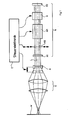
- FIG. 1 The most important components of a laser processing device according to the invention can be seen in FIG. 1. These are a laser generator G for generating a laser beam L, optics 0 for focusing the laser beam onto a workpiece W, a beam expander A and control electronics E controlling the generator G and beam expander A.
- the laser generator G consists of a resonator defined by two mirrors M 1 and M 2 , an active medium AM, a Q switch Q and a mode diaphragm MB.
- the device shown corresponds to the state of the art and therefore requires no further explanation.
- the mode diaphragm MB and the beam expander A are not permanently mounted or set, but their effect can be changed or adjusted via servo means indicated only by arrows. In this way, the beam parameters can be easily and quickly adapted to the most diverse operating requirements via control electronics.
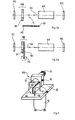
- the mode diaphragm MB consists of a fixed diaphragm part B 1 which is permanently in the beam path and a movable diaphragm part B 2 which can be swiveled into the beam path and whose axis of rotation A 2 crosses the optical axis OA of the system perpendicularly or parallel to or in the Level of the movable panel part B 2 is.
- a large beam cross section results, when the diaphragm part B 2 (FIG. 2b) is pivoted in, a correspondingly smaller one.
- FIG. 3 shows a practical embodiment of a changeable mode diaphragm MB.
- the fixed diaphragm part is designed in a conventional manner as a tube 10 with a threaded connector 11, which is screwed into an adjustment bracket, not shown.
- a bracket 20 is attached to the tube 10 and fixed with grub screws 12.
- a DC motor 30 is fastened in the bracket 20, the shaft 31 of which carries a lamella 40 which forms the movable diaphragm part B 2 .
- a stop pin 50 limits the pivoting movement of the lamella 40 in the direction away from the tube 10.
- the lamella 40 can be pivoted into the beam path in front of the tube 10 or pivoted out of it. With an appropriate choice of motor, this can be done e.g. B. done very easily using TTL signals.
- an aperture revolver wheel with different apertures
- continuously adjustable apertures iris apertures
- FIG. 5a and 5b show another possibility for the selection of different transverse modes of the laser.
- an aperture B 7 is rotated about a pivot axis A 7 lying in its plane and intersecting the optical axis OA of the system, and thus the effective beam cross section is changed.
- FIG. 5a there is, for example, a laser beam with TEMl 1 mode, in the position shown in FIG. 5b one with TEM 0.1 mode.
- the beam should be influenced quickly, continuously and if possible without large mechanical movements.
- SLM spatial light modulator element
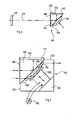
- This modulator element ME essentially consists of a totally reflecting deflection prism 100, one side surface 101 of which is oriented perpendicularly and the other side surface 102 of which is aligned parallel to the optical axis OA of the laser resonator.
- the vertical side surface 101 is provided with an antireflection coating AR, the parallel side surface 102 carries the resonator mirror M2.
- a concave plate 110 which is transparent to the laser radiation and is made of an elastically somewhat deformable material (for example glass), is provided on the base surface 103 of the deflecting prism 100.
- This plate 110 is pressed against the base surface 103 of the prism 100 by means of a piezo-electric adjustment element 120, which is supported on a counter bearing 130, so that it rests on the base surface 103 along its edge 111.
- the piezoelectric adjustment element 120 is connected to an adjustable voltage source 150, which in practice is formed by the control electronics E. Depending on the applied voltage, the piezo-electric adjusting element 120 then presses the plate 110 more or less strongly to the deflection prism 100.
- the air gap 160 changes between the concave side of the plate 110 and the base surface 103 and thus changes the mode distribution of the laser beam.
- the modulator element ME works on the principle of frustrated total reflection, also called optical tunnel effect. If only the prism were present, the laser beam would be totally reflected at the base surface. The "transversely damped wave" excited on the base surface cannot be radiated into the optically thinner medium for electrodynamic reasons. However, if plate 110 is now approached to the base surface, the surface wave is influenced and can radiate part of its energy into the approximated plate. As a result, the incident wave is no longer totally reflected, but only to a fraction that depends on the distance of the plate. By modulating the distance between the plates, the shaft can be modulated.
- the invention does not use a flat, but rather a concave plate 100, so that the air gap varies as a function of the location.
- the reflectivity is also so great that laser emission can take place.
- This area corresponds to the free opening in a conventional mode diaphragm.
- the modulator element ME therefore corresponds to an electrically continuously adjustable diaphragm for mode selection of a laser.
- the shape of the effective "opening" of this mode selector can be varied e.g. B. by the shape of the approximate plate by the design of the mechanical transition between the piezoelectric element and the back of the plate, by the design of the prism, or by means of additional elements in the laser resonator (z. B. cylindrical lenses). It also goes without saying that the plate does not necessarily have to be in direct contact with the base surface of the prism, but can also be arranged at a distance from it with a suitable shape.
- the laser beam L can be transformed outside the resonator by means of adaptive-optical elements, preferably coupled with the beam manipulations within the resonator.
- adaptive-optical elements are motor-displaceable optical components (lenses, mirrors, gratings, prisms, holograms, diaphragms) and electrically controllable optical elements (liquid crystal cells, deformable mirrors and other elements, spatial and temporal light modulators, attenuators, etc.).
- motor-displaceable optical components laenses, mirrors, gratings, prisms, holograms, diaphragms
- electrically controllable optical elements liquid crystal cells, deformable mirrors and other elements, spatial and temporal light modulators, attenuators, etc.
- the invention described above thus provides modifiable mode-selective means in the resonator, which enable the servo-controlled adjustment of the beam parameters (mode structure, divergence, beam diameter, power) for the respective operating case via computer.
Landscapes
- Physics & Mathematics (AREA)
- Optics & Photonics (AREA)
- Engineering & Computer Science (AREA)
- Plasma & Fusion (AREA)
- General Physics & Mathematics (AREA)
- Mechanical Engineering (AREA)
- Electromagnetism (AREA)
- Lasers (AREA)
- Laser Beam Processing (AREA)
- Mechanical Light Control Or Optical Switches (AREA)
Applications Claiming Priority (2)
| Application Number | Priority Date | Filing Date | Title |
|---|---|---|---|
| CH5848/83 | 1983-10-28 | ||
| CH584883 | 1983-10-28 |
Publications (3)
| Publication Number | Publication Date |
|---|---|
| EP0143743A1 true EP0143743A1 (fr) | 1985-06-05 |
| EP0143743B1 EP0143743B1 (fr) | 1987-03-04 |
| EP0143743B2 EP0143743B2 (fr) | 1991-03-13 |
Family
ID=4300314
Family Applications (1)
| Application Number | Title | Priority Date | Filing Date |
|---|---|---|---|
| EP84810512A Expired - Lifetime EP0143743B2 (fr) | 1983-10-28 | 1984-10-22 | Dispositif laser pour le traitement des matériaux |
Country Status (4)
| Country | Link |
|---|---|
| US (1) | US4675500A (fr) |
| EP (1) | EP0143743B2 (fr) |
| JP (1) | JPS60111788A (fr) |
| DE (1) | DE3462568D1 (fr) |
Cited By (11)
| Publication number | Priority date | Publication date | Assignee | Title |
|---|---|---|---|---|
| WO1987001819A3 (fr) * | 1985-09-11 | 1987-04-23 | Rodenstock Instr | Dispositif generateur d'un spot de rayon laser de grandeur reglable |
| EP0296497A1 (fr) * | 1987-06-19 | 1988-12-28 | EUROPÄISCHE WIRTSCHAFTSGEMEINSCHAFT Bâtiment Jean Monnet | Dispositif pour faire varier en continu la puissance d'un laser |
| GB2228440A (en) * | 1988-12-08 | 1990-08-29 | Andrew Victor Polijanczuk | Improvements to soldering by laser |
| FR2647042A1 (fr) * | 1989-05-18 | 1990-11-23 | Diehl Gmbh & Co | Dispositif de guidage de faisceau pour l'usinage de pieces au laser |
| EP0360165A3 (fr) * | 1988-09-19 | 1991-09-25 | Firma Carl Zeiss | Dispositif laser avec conversion de fréquence commutable |
| EP0428734A4 (fr) * | 1989-05-08 | 1992-02-24 | ||
| US5237150A (en) * | 1990-01-19 | 1993-08-17 | Fanuc Ltd. | Method of cutting workpiece with laser beam |
| WO2007056595A1 (fr) * | 2005-11-09 | 2007-05-18 | Thomson Licensing | Regleur de couture optique |
| EP1850165A1 (fr) * | 2006-04-27 | 2007-10-31 | Ricoh Company, Ltd. | Système de source lumineuse, lecteur optique, appareil de formation d'images, procédé de contrôle de la quantité de lumière, procédé de lecture optique et procédé de formation d'images |
| EP1944839A3 (fr) * | 2007-01-12 | 2010-03-17 | Peacock LLC | Cavité de laser en particulier pour un appareil de soudure au laser |
| CN101862901A (zh) * | 2010-06-21 | 2010-10-20 | 苏州市博海激光科技有限公司 | 聚焦光点无规则偏转的激光辊类表面毛化加工方法及装置 |
Families Citing this family (35)
| Publication number | Priority date | Publication date | Assignee | Title |
|---|---|---|---|---|
| US4910739A (en) * | 1988-03-21 | 1990-03-20 | Spectra-Physics | Adjustable aperture |
| US4977575A (en) * | 1989-08-24 | 1990-12-11 | Spectra-Physics, Inc. | Adjustable aperture comprising a shape memory alloy and laser using same |
| DE3930495C2 (de) * | 1989-09-12 | 1996-11-07 | Rofin Sinar Laser Gmbh | Einrichtung zum Einstellen von Fokusdurchmesser und Fokuslage eines Laserstrahls |
| DE4018006A1 (de) * | 1990-06-05 | 1991-12-12 | Baasel Carl Lasertech | Laser mit modenblende |
| EP0599154A1 (fr) * | 1992-11-20 | 1994-06-01 | Ascom Tech Ag | Modulateur pour un faisceau de lumière |
| US5455709A (en) * | 1993-03-23 | 1995-10-03 | Martin Marietta Corporation | Total internal reflection spatial light modulation apparatus and method of fabrication thereof |
| JP3399590B2 (ja) * | 1993-08-04 | 2003-04-21 | 富士通株式会社 | 配線の切断装置 |
| US5444723A (en) * | 1993-08-18 | 1995-08-22 | Institut National D'optique | Optical switch and Q-switched laser |
| AUPM316293A0 (en) * | 1993-12-24 | 1994-07-28 | Electro Optic Systems Pty Limited | Improved laser cavity assembly |
| JP3159593B2 (ja) * | 1994-02-28 | 2001-04-23 | 三菱電機株式会社 | レーザ加工方法及びその装置 |
| US5656186A (en) * | 1994-04-08 | 1997-08-12 | The Regents Of The University Of Michigan | Method for controlling configuration of laser induced breakdown and ablation |
| DE19549531B4 (de) * | 1994-10-14 | 2007-12-13 | Mitsubishi Denki K.K. | Festkörperlaservorrichtung und Laserbearbeitungsvorrichtung |
| US5491319A (en) * | 1994-12-19 | 1996-02-13 | International Business Machines Corporation | Laser ablation apparatus and method |
| WO1997016387A1 (fr) * | 1995-11-03 | 1997-05-09 | Anatoly Valentinovich Vasilev | Procede de formation par laser d'une image dans des objets transparents |
| US5834094A (en) * | 1996-09-30 | 1998-11-10 | Surface Technologies Ltd. | Bearing having micropores and design method thereof |
| US5808780A (en) * | 1997-06-09 | 1998-09-15 | Texas Instruments Incorporated | Non-contacting micromechanical optical switch |
| US6926487B1 (en) | 1998-04-28 | 2005-08-09 | Rexam Ab | Method and apparatus for manufacturing marked articles to be included in cans |
| JP3178524B2 (ja) * | 1998-11-26 | 2001-06-18 | 住友重機械工業株式会社 | レーザマーキング方法と装置及びマーキングされた部材 |
| US6449081B1 (en) * | 1999-06-16 | 2002-09-10 | Canon Kabushiki Kaisha | Optical element and optical device having it |
| US6479787B1 (en) * | 1999-10-05 | 2002-11-12 | Rexam Ab | Laser unit and method for engraving articles to be included in cans |
| US6455806B1 (en) | 2000-01-14 | 2002-09-24 | Rexam Ab | Arrangement for shaping and marking a target |
| US6872913B1 (en) | 2000-01-14 | 2005-03-29 | Rexam Ab | Marking of articles to be included in cans |
| US6926456B1 (en) | 2000-01-20 | 2005-08-09 | Rexam Ab | Guiding device for a marking arrangement |
| US6341009B1 (en) | 2000-02-24 | 2002-01-22 | Quantronix Corporation | Laser delivery system and method for photolithographic mask repair |
| US6576871B1 (en) | 2000-04-03 | 2003-06-10 | Rexam Ab | Method and device for dust protection in a laser processing apparatus |
| RU2234779C2 (ru) * | 2001-12-17 | 2004-08-20 | Сафронов Андрей Геннадьевич | Способ управления лазерным резонатором и устройство на его основе |
| DE10245617A1 (de) * | 2002-09-30 | 2004-04-08 | Eos Gmbh Electro Optical Systems | Vorrichtung und Verfahren zum schichtweisen Herstellen von dreidimensionalen Objekten |
| DE50310675D1 (de) * | 2003-07-18 | 2008-12-04 | Trumpf Laser Gmbh & Co Kg | Laserbearbeitungsmaschine mit Modulator zum Verändern der Laserleistung |
| US7645300B2 (en) | 2004-02-02 | 2010-01-12 | Visiogen, Inc. | Injector for intraocular lens system |
| DE102004027621A1 (de) * | 2004-06-05 | 2006-01-12 | Rehau Ag + Co. | Laserstrahlmarkiervorrichtung, Laserstrahlmarkierverfahren sowie Verwendung einer Laserstrahlmarkiervorrichtung |
| US7249855B2 (en) * | 2004-12-21 | 2007-07-31 | Hewlett-Packard Development Company, L.P. | System and method of image enhancement through light intensity modulation in digital projectors |
| US20070211352A1 (en) * | 2006-03-09 | 2007-09-13 | Nikon Corporation | Aperture changing apparatus and method |
| US8598488B2 (en) | 2011-12-23 | 2013-12-03 | Electro Scientific Industries, Inc. | Method and apparatus for adjusting radiation spot size |
| JP5964621B2 (ja) * | 2012-03-16 | 2016-08-03 | 株式会社ディスコ | レーザー加工装置 |
| JP6306659B1 (ja) * | 2016-10-19 | 2018-04-04 | ファナック株式会社 | ビーム分配器 |
Citations (7)
| Publication number | Priority date | Publication date | Assignee | Title |
|---|---|---|---|---|
| US3426293A (en) * | 1964-10-07 | 1969-02-04 | American Optical Corp | Diaphragm tuning of gas laser |
| US3689159A (en) * | 1970-06-11 | 1972-09-05 | Mitsubishi Electric Corp | Laser processing apparatus |
| US3689293A (en) | 1970-07-08 | 1972-09-05 | Corning Glass Works | Mica glass-ceramics |
| US3940712A (en) | 1974-04-11 | 1976-02-24 | White Matthew B | Modulation techniques for lasers |
| FR2377662A1 (fr) * | 1977-01-18 | 1978-08-11 | Leitz Ernst Gmbh | Regulateur de flux lumineux |
| US4283115A (en) * | 1978-06-28 | 1981-08-11 | Richard Wolf Gmbh | Beam splitters for endoscopes comprising a dual observation system |
| WO1981002953A1 (fr) | 1980-04-05 | 1981-10-15 | Eltro Gmbh | Laser a guide d'onde avec element de frustration |
Family Cites Families (11)
| Publication number | Priority date | Publication date | Assignee | Title |
|---|---|---|---|---|
| DE674294C (de) * | 1933-02-17 | 1939-04-12 | Tobis Tonbild Syndikat Akt Ges | Verfahren zur Umwandlung elektrischer Stromschwankungen in Lichtschwankungen |
| US3292102A (en) * | 1962-12-14 | 1966-12-13 | Francis T Byrne | Pulsed optical beam generator |
| US3500240A (en) * | 1964-11-30 | 1970-03-10 | Us Navy | Simple traveling wave laser using total - internal - reflection resonator |
| US3514183A (en) * | 1967-11-06 | 1970-05-26 | Ibm | Light deflector system |
| US3699474A (en) * | 1971-11-20 | 1972-10-17 | Atomic Energy Commission | Multiple beam laser system |
| BE792829A (fr) * | 1971-12-17 | 1973-03-30 | Siemens Ag | Dispositif pour devier, de facon controlee, des rayonnements optiques |
| US4032861A (en) * | 1973-11-15 | 1977-06-28 | Union Carbide Corporation | Laser device for altering surfaces in accordance with given patterns |
| JPS5368499A (en) * | 1976-11-30 | 1978-06-17 | Komatsu Ltd | Method of shaping laser beam used for machining |
| US4323317A (en) * | 1980-05-07 | 1982-04-06 | Shibuya Kogyo Company, Ltd. | Pattern controlling device for laser marker |
| US4430548A (en) * | 1982-04-26 | 1984-02-07 | Macken John A | Laser apparatus and process for cutting paper |
| US4494235A (en) * | 1983-09-27 | 1985-01-15 | Gte Government Systems Corporation | Multiple wavelength laser |
-
1984
- 1984-10-22 DE DE8484810512T patent/DE3462568D1/de not_active Expired
- 1984-10-22 EP EP84810512A patent/EP0143743B2/fr not_active Expired - Lifetime
- 1984-10-24 JP JP59222317A patent/JPS60111788A/ja active Pending
- 1984-10-29 US US06/665,998 patent/US4675500A/en not_active Expired - Fee Related
Patent Citations (7)
| Publication number | Priority date | Publication date | Assignee | Title |
|---|---|---|---|---|
| US3426293A (en) * | 1964-10-07 | 1969-02-04 | American Optical Corp | Diaphragm tuning of gas laser |
| US3689159A (en) * | 1970-06-11 | 1972-09-05 | Mitsubishi Electric Corp | Laser processing apparatus |
| US3689293A (en) | 1970-07-08 | 1972-09-05 | Corning Glass Works | Mica glass-ceramics |
| US3940712A (en) | 1974-04-11 | 1976-02-24 | White Matthew B | Modulation techniques for lasers |
| FR2377662A1 (fr) * | 1977-01-18 | 1978-08-11 | Leitz Ernst Gmbh | Regulateur de flux lumineux |
| US4283115A (en) * | 1978-06-28 | 1981-08-11 | Richard Wolf Gmbh | Beam splitters for endoscopes comprising a dual observation system |
| WO1981002953A1 (fr) | 1980-04-05 | 1981-10-15 | Eltro Gmbh | Laser a guide d'onde avec element de frustration |
Cited By (14)
| Publication number | Priority date | Publication date | Assignee | Title |
|---|---|---|---|---|
| US4887019A (en) * | 1985-09-11 | 1989-12-12 | G. Rodenstock Instruments Gmbh | Device for the generation of a laser beam spot of adjustable size |
| WO1987001819A3 (fr) * | 1985-09-11 | 1987-04-23 | Rodenstock Instr | Dispositif generateur d'un spot de rayon laser de grandeur reglable |
| EP0296497A1 (fr) * | 1987-06-19 | 1988-12-28 | EUROPÄISCHE WIRTSCHAFTSGEMEINSCHAFT Bâtiment Jean Monnet | Dispositif pour faire varier en continu la puissance d'un laser |
| EP0360165A3 (fr) * | 1988-09-19 | 1991-09-25 | Firma Carl Zeiss | Dispositif laser avec conversion de fréquence commutable |
| GB2228440A (en) * | 1988-12-08 | 1990-08-29 | Andrew Victor Polijanczuk | Improvements to soldering by laser |
| EP0428734A4 (fr) * | 1989-05-08 | 1992-02-24 | ||
| FR2647042A1 (fr) * | 1989-05-18 | 1990-11-23 | Diehl Gmbh & Co | Dispositif de guidage de faisceau pour l'usinage de pieces au laser |
| US5237150A (en) * | 1990-01-19 | 1993-08-17 | Fanuc Ltd. | Method of cutting workpiece with laser beam |
| EP0464213A4 (en) * | 1990-01-19 | 1993-09-29 | Fanuc Ltd. | Method of laser cutting work |
| WO2007056595A1 (fr) * | 2005-11-09 | 2007-05-18 | Thomson Licensing | Regleur de couture optique |
| EP1850165A1 (fr) * | 2006-04-27 | 2007-10-31 | Ricoh Company, Ltd. | Système de source lumineuse, lecteur optique, appareil de formation d'images, procédé de contrôle de la quantité de lumière, procédé de lecture optique et procédé de formation d'images |
| US8085457B2 (en) | 2006-04-27 | 2011-12-27 | Ricoh Company, Ltd. | Light source system, optical scanner, image forming apparatus, and light-amount control method |
| EP1944839A3 (fr) * | 2007-01-12 | 2010-03-17 | Peacock LLC | Cavité de laser en particulier pour un appareil de soudure au laser |
| CN101862901A (zh) * | 2010-06-21 | 2010-10-20 | 苏州市博海激光科技有限公司 | 聚焦光点无规则偏转的激光辊类表面毛化加工方法及装置 |
Also Published As
| Publication number | Publication date |
|---|---|
| JPS60111788A (ja) | 1985-06-18 |
| US4675500A (en) | 1987-06-23 |
| EP0143743B1 (fr) | 1987-03-04 |
| DE3462568D1 (en) | 1987-04-09 |
| EP0143743B2 (fr) | 1991-03-13 |
Similar Documents
| Publication | Publication Date | Title |
|---|---|---|
| EP0143743B1 (fr) | Dispositif laser pour le traitement des matériaux | |
| EP1066546B1 (fr) | Procede et dispositif d'amplification par resonance, permettant notamment la conversion de frequence reglable d'un rayonnement laser | |
| DE68920765T2 (de) | Zusammenbau von elektrooptischen Halbleiter-Bauelementen. | |
| DE19955599B4 (de) | Laser mit Wellenlängenumwandlung und Bearbeitungsvorrichtung mit einem solchen Laser | |
| EP2363928B1 (fr) | Montage de diodes laser à bruit réduit | |
| EP0167843B1 (fr) | Disposition de modulation externe de la radiation d'un laser à CO2 à puissance élevée | |
| DE2403501B2 (de) | Verfahren zur Regelung der Phasenanpassung einer kohärenten Sekundärstrahlung in einem nichtlinearen Kristall | |
| DE69921710T2 (de) | Laserquelle mit kontinuierlich abstimmbarer Wellenlänge | |
| DE102020200798B4 (de) | Verfahren zur Lasermaterialbearbeitung mittels eines in seinem Leistungsprofil verstellbaren Bearbeitungslaserstrahls | |
| DE60004237T2 (de) | LASER-Generatorsystem | |
| DE102019131827B4 (de) | Frequenzkonversionsanordnung zur Optimierung von Eigenschaften einer Harmonischen eines Lasers | |
| DE4335585A1 (de) | Laservorrichtung | |
| AT1859U1 (de) | Kurzpuls-laservorrichtung | |
| WO1999054782A1 (fr) | Procede et dispositif de conversion de frequence, notamment de doublement de la frequence de lasers a frequence fixe | |
| DE19946176A1 (de) | Diodengepumpter Laser mit interner Frequenzverdopplung | |
| EP4263118A1 (fr) | Dispositif pour influer sur le faisceau d'un faisceau laser | |
| CH692638A5 (de) | Vorrichtung zum unterbrechungsfreien Auslenken eines Lichtstrahls. | |
| EP1116064B1 (fr) | Procede et dispositif pour la mise en forme du profil d'intensite d'un faisceau laser | |
| DE102018201490B3 (de) | XY-Ablenkeinheit für UV-Laserlicht sowie deren Verwendung | |
| EP0599154A1 (fr) | Modulateur pour un faisceau de lumière | |
| EP0360165B1 (fr) | Dispositif laser avec conversion de fréquence commutable | |
| EP0692741A1 (fr) | Dispositif de fabrication pour écran sérigraphique | |
| DE4212779A1 (de) | Laser und Steuer- und Regelverfahren dafür | |
| DE10058990C2 (de) | Vorrichtung zur Bestrahlung eines Objektes für eine Aufzeichnung eines visuellen Produktes | |
| EP1485738A1 (fr) | Procede et dispositif d'epissurage de fibres optiques |
Legal Events
| Date | Code | Title | Description |
|---|---|---|---|
| PUAI | Public reference made under article 153(3) epc to a published international application that has entered the european phase |
Free format text: ORIGINAL CODE: 0009012 |
|
| 17P | Request for examination filed |
Effective date: 19841024 |
|
| AK | Designated contracting states |
Designated state(s): CH DE FR GB IT LI |
|
| 17Q | First examination report despatched |
Effective date: 19860509 |
|
| GRAA | (expected) grant |
Free format text: ORIGINAL CODE: 0009210 |
|
| AK | Designated contracting states |
Kind code of ref document: B1 Designated state(s): CH DE FR GB IT LI |
|
| REF | Corresponds to: |
Ref document number: 3462568 Country of ref document: DE Date of ref document: 19870409 |
|
| RAP2 | Party data changed (patent owner data changed or rights of a patent transferred) |
Owner name: CIBA-GEIGY AG |
|
| ET | Fr: translation filed | ||
| REG | Reference to a national code |
Ref country code: CH Ref legal event code: PUE Owner name: CIBA-GEIGY AG |
|
| ITF | It: translation for a ep patent filed | ||
| PLBI | Opposition filed |
Free format text: ORIGINAL CODE: 0009260 |
|
| PLBI | Opposition filed |
Free format text: ORIGINAL CODE: 0009260 |
|
| 26 | Opposition filed |
Opponent name: SIEMENS AKTIENGESELLSCHAFT, BERLIN UND MUENCHEN Effective date: 19871126 |
|
| 26 | Opposition filed |
Opponent name: CARL BAASEL LASERTECHNIK GMBH Effective date: 19871130 |
|
| REG | Reference to a national code |
Ref country code: CH Ref legal event code: PUE Owner name: HAAS LASER SYSTEMS AG |
|
| ITPR | It: changes in ownership of a european patent |
Owner name: CESSIONE;HAAS LASER SYSTEMS AG |
|
| ITF | It: translation for a ep patent filed | ||
| REG | Reference to a national code |
Ref country code: GB Ref legal event code: 732 |
|
| REG | Reference to a national code |
Ref country code: FR Ref legal event code: TP |
|
| PUAH | Patent maintained in amended form |
Free format text: ORIGINAL CODE: 0009272 |
|
| STAA | Information on the status of an ep patent application or granted ep patent |
Free format text: STATUS: PATENT MAINTAINED AS AMENDED |
|
| 27A | Patent maintained in amended form |
Effective date: 19910313 |
|
| AK | Designated contracting states |
Kind code of ref document: B2 Designated state(s): CH DE FR GB IT LI |
|
| ET3 | Fr: translation filed ** decision concerning opposition | ||
| REG | Reference to a national code |
Ref country code: CH Ref legal event code: AEN |
|
| ITTA | It: last paid annual fee | ||
| PGFP | Annual fee paid to national office [announced via postgrant information from national office to epo] |
Ref country code: GB Payment date: 19921009 Year of fee payment: 9 |
|
| PGFP | Annual fee paid to national office [announced via postgrant information from national office to epo] |
Ref country code: FR Payment date: 19921015 Year of fee payment: 9 |
|
| PGFP | Annual fee paid to national office [announced via postgrant information from national office to epo] |
Ref country code: DE Payment date: 19921030 Year of fee payment: 9 |
|
| PGFP | Annual fee paid to national office [announced via postgrant information from national office to epo] |
Ref country code: CH Payment date: 19921118 Year of fee payment: 9 |
|
| PG25 | Lapsed in a contracting state [announced via postgrant information from national office to epo] |
Ref country code: GB Effective date: 19931022 |
|
| PG25 | Lapsed in a contracting state [announced via postgrant information from national office to epo] |
Ref country code: LI Effective date: 19931031 Ref country code: CH Effective date: 19931031 |
|
| GBPC | Gb: european patent ceased through non-payment of renewal fee |
Effective date: 19931022 |
|
| PG25 | Lapsed in a contracting state [announced via postgrant information from national office to epo] |
Ref country code: FR Effective date: 19940630 |
|
| REG | Reference to a national code |
Ref country code: CH Ref legal event code: PL |
|
| PG25 | Lapsed in a contracting state [announced via postgrant information from national office to epo] |
Ref country code: DE Effective date: 19940701 |
|
| REG | Reference to a national code |
Ref country code: FR Ref legal event code: ST |