EP0143894A2 - Procédé pour la réalisation de réactions chimiques notamment pour la fabrication de matières plastiques à l'aide de machines à extruder et installation à cet effet - Google Patents
Procédé pour la réalisation de réactions chimiques notamment pour la fabrication de matières plastiques à l'aide de machines à extruder et installation à cet effet Download PDFInfo
- Publication number
- EP0143894A2 EP0143894A2 EP84109569A EP84109569A EP0143894A2 EP 0143894 A2 EP0143894 A2 EP 0143894A2 EP 84109569 A EP84109569 A EP 84109569A EP 84109569 A EP84109569 A EP 84109569A EP 0143894 A2 EP0143894 A2 EP 0143894A2
- Authority
- EP
- European Patent Office
- Prior art keywords
- temperature
- fluid
- extruder
- zones
- housing section
- Prior art date
- Legal status (The legal status is an assumption and is not a legal conclusion. Google has not performed a legal analysis and makes no representation as to the accuracy of the status listed.)
- Granted
Links
Images

Classifications
-
- B—PERFORMING OPERATIONS; TRANSPORTING
- B29—WORKING OF PLASTICS; WORKING OF SUBSTANCES IN A PLASTIC STATE IN GENERAL
- B29C—SHAPING OR JOINING OF PLASTICS; SHAPING OF MATERIAL IN A PLASTIC STATE, NOT OTHERWISE PROVIDED FOR; AFTER-TREATMENT OF THE SHAPED PRODUCTS, e.g. REPAIRING
- B29C48/00—Extrusion moulding, i.e. expressing the moulding material through a die or nozzle which imparts the desired form; Apparatus therefor
- B29C48/022—Extrusion moulding, i.e. expressing the moulding material through a die or nozzle which imparts the desired form; Apparatus therefor characterised by the choice of material
-
- B—PERFORMING OPERATIONS; TRANSPORTING
- B29—WORKING OF PLASTICS; WORKING OF SUBSTANCES IN A PLASTIC STATE IN GENERAL
- B29C—SHAPING OR JOINING OF PLASTICS; SHAPING OF MATERIAL IN A PLASTIC STATE, NOT OTHERWISE PROVIDED FOR; AFTER-TREATMENT OF THE SHAPED PRODUCTS, e.g. REPAIRING
- B29C48/00—Extrusion moulding, i.e. expressing the moulding material through a die or nozzle which imparts the desired form; Apparatus therefor
- B29C48/25—Component parts, details or accessories; Auxiliary operations
- B29C48/78—Thermal treatment of the extrusion moulding material or of preformed parts or layers, e.g. by heating or cooling
- B29C48/80—Thermal treatment of the extrusion moulding material or of preformed parts or layers, e.g. by heating or cooling at the plasticising zone, e.g. by heating cylinders
- B29C48/83—Heating or cooling the cylinders
-
- B—PERFORMING OPERATIONS; TRANSPORTING
- B29—WORKING OF PLASTICS; WORKING OF SUBSTANCES IN A PLASTIC STATE IN GENERAL
- B29C—SHAPING OR JOINING OF PLASTICS; SHAPING OF MATERIAL IN A PLASTIC STATE, NOT OTHERWISE PROVIDED FOR; AFTER-TREATMENT OF THE SHAPED PRODUCTS, e.g. REPAIRING
- B29C48/00—Extrusion moulding, i.e. expressing the moulding material through a die or nozzle which imparts the desired form; Apparatus therefor
- B29C48/25—Component parts, details or accessories; Auxiliary operations
- B29C48/78—Thermal treatment of the extrusion moulding material or of preformed parts or layers, e.g. by heating or cooling
- B29C48/875—Thermal treatment of the extrusion moulding material or of preformed parts or layers, e.g. by heating or cooling for achieving a non-uniform temperature distribution, e.g. using barrels having both cooling and heating zones
-
- B—PERFORMING OPERATIONS; TRANSPORTING
- B29—WORKING OF PLASTICS; WORKING OF SUBSTANCES IN A PLASTIC STATE IN GENERAL
- B29C—SHAPING OR JOINING OF PLASTICS; SHAPING OF MATERIAL IN A PLASTIC STATE, NOT OTHERWISE PROVIDED FOR; AFTER-TREATMENT OF THE SHAPED PRODUCTS, e.g. REPAIRING
- B29C48/00—Extrusion moulding, i.e. expressing the moulding material through a die or nozzle which imparts the desired form; Apparatus therefor
- B29C48/25—Component parts, details or accessories; Auxiliary operations
- B29C48/92—Measuring, controlling or regulating
-
- B—PERFORMING OPERATIONS; TRANSPORTING
- B29—WORKING OF PLASTICS; WORKING OF SUBSTANCES IN A PLASTIC STATE IN GENERAL
- B29C—SHAPING OR JOINING OF PLASTICS; SHAPING OF MATERIAL IN A PLASTIC STATE, NOT OTHERWISE PROVIDED FOR; AFTER-TREATMENT OF THE SHAPED PRODUCTS, e.g. REPAIRING
- B29C2948/00—Indexing scheme relating to extrusion moulding
- B29C2948/92—Measuring, controlling or regulating
- B29C2948/92504—Controlled parameter
- B29C2948/92704—Temperature
-
- B—PERFORMING OPERATIONS; TRANSPORTING
- B29—WORKING OF PLASTICS; WORKING OF SUBSTANCES IN A PLASTIC STATE IN GENERAL
- B29C—SHAPING OR JOINING OF PLASTICS; SHAPING OF MATERIAL IN A PLASTIC STATE, NOT OTHERWISE PROVIDED FOR; AFTER-TREATMENT OF THE SHAPED PRODUCTS, e.g. REPAIRING
- B29C2948/00—Indexing scheme relating to extrusion moulding
- B29C2948/92—Measuring, controlling or regulating
- B29C2948/92504—Controlled parameter
- B29C2948/92809—Particular value claimed
-
- B—PERFORMING OPERATIONS; TRANSPORTING
- B29—WORKING OF PLASTICS; WORKING OF SUBSTANCES IN A PLASTIC STATE IN GENERAL
- B29C—SHAPING OR JOINING OF PLASTICS; SHAPING OF MATERIAL IN A PLASTIC STATE, NOT OTHERWISE PROVIDED FOR; AFTER-TREATMENT OF THE SHAPED PRODUCTS, e.g. REPAIRING
- B29C2948/00—Indexing scheme relating to extrusion moulding
- B29C2948/92—Measuring, controlling or regulating
- B29C2948/92819—Location or phase of control
- B29C2948/92857—Extrusion unit
- B29C2948/92876—Feeding, melting, plasticising or pumping zones, e.g. the melt itself
- B29C2948/92895—Barrel or housing
-
- B—PERFORMING OPERATIONS; TRANSPORTING
- B29—WORKING OF PLASTICS; WORKING OF SUBSTANCES IN A PLASTIC STATE IN GENERAL
- B29C—SHAPING OR JOINING OF PLASTICS; SHAPING OF MATERIAL IN A PLASTIC STATE, NOT OTHERWISE PROVIDED FOR; AFTER-TREATMENT OF THE SHAPED PRODUCTS, e.g. REPAIRING
- B29C48/00—Extrusion moulding, i.e. expressing the moulding material through a die or nozzle which imparts the desired form; Apparatus therefor
- B29C48/03—Extrusion moulding, i.e. expressing the moulding material through a die or nozzle which imparts the desired form; Apparatus therefor characterised by the shape of the extruded material at extrusion
- B29C48/12—Articles with an irregular circumference when viewed in cross-section, e.g. window profiles
Definitions
- the invention relates to a process for carrying out chemical reactions, in particular for the production of plastics with the aid of extruders, and to a plant for carrying out this process.
- Extruders for processing plastics require a relatively large amount of energy during operation, and the desired precise temperature control is often not possible, even if the extruders are equipped with electrical heating and with cooling coils for a cooling liquid. It has also been proposed to produce thermoplastic materials on extruders, but this type of production has not been able to establish itself because of the difficulties encountered. However, there is a need for flexible use and for different chemical reactions to have available usable reactors that are designed for the production of small to medium product quantities and can be converted with little effort.
- the object of the invention is to provide a method for carrying out chemical reactions, in particular for the production of plastics with the aid of extruders, and systems suitable for this purpose which enable the targeted implementation of various chemical reactions, in particular the production of thermoplastic plastics.
- this object is achieved by creating a very sensitive temperature control for the extruder, which makes it possible to maintain precise temperature limits.
- the transport route of the extruder is divided into different temperature zones, the temperature in these zones being set individually and independently of one another. At least five temperature zones are advantageously provided and generally five to fifteen or more zones, with approximately ten zones per extruder being preferred. The number of zones essentially depends on the temperature sensitivity of a reaction to be carried out.
- a predetermined temperature profile can be imposed on the transport route in the extruder, whereby it can be achieved that chemical reactions taking place while passing through the transport route are localized to certain zones despite the continuous conveyance of the material.
- the temperature zones are temperature-controlled exclusively with the aid of fluids, in particular liquids, which flow through the temperature zones.
- the extruder can be designed to be explosion-proof, which is preferred.
- the temperature control according to the invention can be carried out very sensitively, so that temperature tolerances below 1 ° C. and even up to 0.1 ° C. can be maintained.
- a mixture of two fluids of the same type but different temperatures is preferably carried out in such a way that the fluid entering the temperature zone is able to absorb or emit quantities of heat in order to maintain the desired temperature, with the smallest possible temperature differences.
- the temperature difference A t between fluid inlet and fluid outlet of the temperature zone can thus be kept below 3 ° C and even below 1 ° C depending on the sensitivity of the reaction.
- the agility of the temperature control is improved in that the fluids are mixed immediately before the respective temperature zone.
- the temperature of one fluid preferably deviates less than 5 ° C., preferably less than 3 ° C., from the target temperature of the corresponding temperature zone, whereas the temperature of the other fluid can advantageously be further away from it. This can be supported by the fact that the amount of fluid flowing through the respective zone is changed.
- the dwell time of the reactants in the individual temperature zones can also be kept different, it being preferably less in zones with a high heat exchange required, whereby the area wetted per unit of time between the material to be treated and the extruder is increased.
- Such measures make it possible to control chemical reactions so precisely that, for example during polymerization processes, the size of the molecular weight of the polymers can be influenced.
- reactions can be prevented by cooling until sufficient mixing of the reactants is achieved and then started very quickly and in a controlled manner by rapid heating to the desired target temperature after the initial cooling.
- Reactions can also be carried out with the extruder under high pressure or under vacuum if the extruder is designed to be pressure-tight.
- the screws of the extruder can preferably be driven at different speeds. If, contrary to expectations, a reaction is too violent, the material can be quickly discharged and the extruder can be self-cleaned by program control by inserting an overdrive.
- Both single-phase and multi-phase reactions can be carried out by the process according to the invention. It is possible to separate parts of the reaction mixture or the reaction medium before the desired product leaves the extruder. For example, liquid components of solid components can be produced by sieving devices known per se be separated. However, it is also possible to remove volatile constituents of the reaction mixture by distillation. Such a distillation can be carried out at ambient pressure. However, vacuum distillation is also possible, in which case, if necessary, a pressure build-up at a point on the transport path which lies before the distillation point prevents volatile reactants from being withdrawn from the reaction medium which has not yet reacted.
- Such a backflow or throttling can be achieved in various ways, for example by providing the screws of the extruder with non-conveying or counter-conveying elements. It is also possible to connect two or more extruders in succession, in which case the discharge nozzle of one extruder then forms the throttle device upstream of the distillation device arranged in the subsequent extruder. In contrast to the conventional degassing devices, which only remove a small percentage of volatiles carried along, such distillation devices can be used to draw off solvents or volatile reaction products formed during the reaction in a stoichiometric amount.
- reaction partners can be added to the reaction medium passing through the transport route in each zone, e.g. B. starters, accelerators or those reactants which are added in part.
- suitable metering openings can be provided in the extruder.
- the start of addition, the amount and the mixing ratio of the reactants, the temperature profile of the transport route, the pressure and / or the screw speed can be predetermined in a program-controlled manner as a function of the desired reaction, as a result of which a wide range of reactions which can be carried out is obtained. It is particularly advantageous to store the variable data of the working or reaction conditions in a database and to call them up depending on the desired properties of the end products, which results in a universal application. In contrast, the previously known extruders intended for carrying out chemical reactions are designed for very specific reactions and are therefore very limited in their possible uses.
- the system according to the invention for carrying out the method advantageously has at least one single-screw or multi-screw extruder, each with at least five housing sections, each for itself, ie. H. are independently temperature-controllable.
- the individual housing sections thus essentially correspond to the temperature zones and are each equipped with their own tepmerization devices.
- the size of the extruder can vary within wide limits.
- B. have a bore diameter of 30 to 120 mm or more, the smaller ones are more suitable for experimental purposes and the larger ones for production purposes.
- the length of a shot corresponds approximately five times the diameter of the bore, but can be varied within wide limits.
- the extruders can process solid, liquid or gaseous raw materials. Two or more extruders can also be cascaded in series, in particular if volatile monomers are processed or volatile by-products are formed.
- the invention further proposes that two screws can rotate in the same direction of rotation. This is a measure which, due to the possibility of tight combing, significantly improves the thorough mixing of plastics.
- the screws are three-course. It has been found that this is the optimal number of extruder screw threads.
- the screws have an incline that changes over their length.
- each housing section has an additional opening. This gives the possibility of introducing a further additive into the extruder at a specific point, connecting pressure measuring devices and / or separating parts of the reaction medium.
- At least one housing section has a degassing opening.
- gaseous substances can be withdrawn, if this corresponds to the ge desired properties is desired.
- the system also has at least one distillation device, preferably a vacuum distillation device, which is connected to an opening in a housing section in order to be able to separate larger amounts of volatile substances.
- the pressure or negative pressure provided for the distillation can be kept adjustable, for which purpose the extruder preferably has a throttle in front of the distillation device.
- the temperature in the distillation zone is also advantageously kept higher than in the other zones in order to increase the vapor pressure of the volatile substances.
- a heat transfer fluid can be provided for temperature control, the temperature of which can be changed by mixing fluid with two different temperatures.
- the two different temperatures from which the desired temperature is mixed are selected so that the target temperature is always at or between these two values.
- a liquid is preferably used as the heat transfer fluid which still has sufficient viscosity and stability at both temperatures.
- Thermal oils that can be used in the range from 50 ° to 200 ° C. or more, for example, and water for low temperature ranges are suitable here.
- the temperature control it can be provided with the aid of a corresponding control that the temperature difference between the fluid at the inlet and the fluid at the outlet does not exceed a certain value, so that the temperature differences within the housing section do not become too great.
- the invention also proposes that, in addition or as an alternative to changing the temperature of the fluid, the amount of the fluid flowing through the housing section can be changed. This is particularly useful if you allows only a small temperature difference between the inlet and outlet fluid in order not to allow excessive temperature differences to occur within the housing section. In this case, the amount of fluid flowing through can be increased.
- At least one servo valve with a preferably continuously variable mixing ratio can be provided for each housing section according to the invention.
- Different types of valves can be used.
- the servo valve can be influenced by at least one temperature sensor via an electronic control for regulating the temperature in the housing section.
- the temperature sensor There are several ways of attaching the temperature sensor, although it is of course also possible to provide more than one temperature sensor at the same time. It can either be possible to switch between the individual temperature sensors or a combination of measured values from several temperature sensors can be used as an input variable for the electronic control.
- the invention proposes that a temperature sensor for measuring the temperature of the housing section is arranged, preferably at a short distance from the inner bore penetrated by the screws. Since the housing bowls are made of metal, this type of temperature can be sensed quite well. However, it is also with Advantage possible that a temperature sensor for measuring the fluid temperature is arranged at the inlet in the housing section. This possibility is particularly valuable if, as is also proposed by the invention, a temperature sensor for measuring the fluid temperature at the outlet from the housing section is arranged. With the help of these two temperature sensors, it can be ensured that the temperature difference between the inlet and the outlet from the housing section does not become too great.
- a temperature sensor is provided if it is arranged in the extruder for measuring the temperature of the melt. Since the threads of the screw pass a short distance from the housing wall, it is still possible, for example, to let a temperature sensor protrude into the interior of the housing, for example in the gusset formed between the two screws, so that it is from the melt, but not from the Snails is touched. This temperature sensor then measures exactly the temperature of the plastic present in the extruder section, and here too, conclusions can be drawn from the temperature differences between the plastic and the housing.
- the type of servo valve proposed by the invention can be implemented in different ways.
- a particularly favorable possibility is given if the servo valve is a three-way valve with two inlets and one outlet, with one branch at each inlet of a fluid circuit, both of which have different temperatures. This means that a fluid circuit with the lowest necessary temperature is present at one input of the three-way valve, while a fluid circuit with the highest necessary temperature is present at the other inlet.
- an outlet temperature can be mixed from both temperature values, which lies between the two extreme values and results in the desired temperature in the shot. It is particularly advantageous if both circuits each have a shunt and a pump.
- the invention further proposes that at least one, preferably both circuits may have a preferably electrical heating with a temperature control and the circuit for the lower temperature may have a heat exchanger for cooling.
- the heating or cooling is necessary to ensure that the two fluid circuits actually deliver fluid at a fixed predetermined temperature, so that it can then be used to mix to the exact temperature.
- the invention further proposes that the outlets of a plurality of housing sections with the exception of the first, which is preferred is water-cooled, lead into common return lines, which can optionally be divided by valves into two parts of different preferred temperatures, the part of higher or lower temperature being connected to the return of the circuit with higher or lower temperature.
- common return lines which can optionally be divided by valves into two parts of different preferred temperatures, the part of higher or lower temperature being connected to the return of the circuit with higher or lower temperature.
- the invention proposes that at least a portion of the fluid leaving the housing section be traceable for the temperature control of the housing section.
- a pump can be provided for the return, wherein the return can also be controlled again with the aid of a valve.
- This measure proposed by the invention is based on the idea that, as a rule, the temperature of the fluid leaving the housing section lies between the two extreme temperatures, so that either a mixture of the returned fluid with the fluid at a lower temperature or with the fluid at a higher temperature for temperature control of the housing section sufficient, which leads to significant energy savings.
- This possibility of recycling can also be carried out with simpler valves, e.g. B. by two or three two-way valves per shot.
- This type of temperature control can also be carried out with two three-way valves or one four-way valve. It is also conceivable to provide a controlled pump so that the mixing ratio is regulated by the delivery rate of the pump. In the extreme case, d. H. For example, complete cooling of all temperature shots can also be provided here that the pump can be switched off.
- the reactants can be mixed in the first zone or zones of the extruder.
- at least two reactants are mixed with one another, possibly with cooling, before entering the extruder.
- at least one metering device with a variable metering quantity is preferably provided, in particular at least two metering pumps with an adjustable stroke being provided, which have a common, controllable drive.
- These variables can also be programmatically changeable, as well as a possible feed pressure with which the starting products are pumped into the extruders.
- thermoplastics in particular those such as are suitable for the production of composite films or composite panels which are waterproof on one side and water-soluble on the other side.
- films or plates are described, for example, in the applicant's European laid-open documents 32 244, 69 296 and 78 553.
- These are composite materials made up of at least two layers, one layer being insoluble in water, but is soluble in acidic or basic medium and the other layer is soluble or soluble in water and contains an acidic or basic solubilizer for the water-insoluble layer.
- the thermoplastic materials can be produced and processed in extruders connected in parallel and / or in series, the heat of reaction released during the production also being able to be used again for melting starting materials or end products in the same or another extruder.
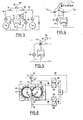
- An extruder 12 consisting of ten housing sections 11 is shown schematically in FIG. 1.
- the extruder 12 has a continuous longitudinal bore in the form of two circular cylinders which are partially established, as can be seen from FIG. 6.
- Two screws 14, 15 are arranged in the housing bore 13, the drive ends 16, 17 of which protrude from the left side of the extruder 12. They are driven there by a rotary drive, the two tightly intermeshing screws 14, 15 rotating in the same direction of rotation in the exemplary embodiment, see also FIG. 6 in this regard.
- the extruder is used in particular for the production of plastics, eg. B. by bulk polymerization.
- the conveying direction of the two screws 14, 15 in the extruder 12 shown in FIG. 1 is from left to right, so that the housing section 11a arranged in FIG. 1 at the left end has a schematically illustrated filling funnel 18 or filler neck for filling plastic or of monomers.
- a schematically illustrated filling funnel 18 or filler neck for filling plastic or of monomers.
- a separate circuit is provided for this purpose, which will be explained in the following. All other housing sections 11 are essentially the same, they are screwed together and form a continuous unit.
- the ninth housing section (second from the right in FIG.
- Fig. 1 the fluid or heat transfer medium circuits are shown with solid lines, the lines indicated by dashed lines are control lines.
- Each housing section 11 contains (in FIG. 1) an inlet 22 at the top and (in FIG. 1 on its underside) an outlet 23 for the heat transfer fluid.
- a servo-operated three-way valve 24 is arranged, each having two inlet sides 25, 26 and an outlet 27.
- the outlet side 27 of each three-way valve 24 is each connected to the inlet 22 of the housing section 11, while in each case one inlet 25 is connected to a fluid circuit 28 of higher temperature and each inlet 26 is connected to a second circuit 29 for a heat transfer fluid at a lower temperature.
- the fluidic circuit 28 is assumed to supply a heat carrier oil with a constant temperature of, for example, 200 ° C., while the fluidic circuit 29 supplies the same heat carrier fluid with the temperature of, for example, 50 ° C.
- a third fluid circuit 33 is provided, which is, for example, water-filled and can have a temperature of 15 °.
- the fluidics Circuit 33 contains a pump 34, a heat exchanger 35, and in addition to the three-way valve 31, a second three-way valve 36.
- the heat exchanger 35 is provided to keep the temperature of the water at exactly 15 °, for which purpose a line 37 is provided for a coolant, the can flow into the heat exchanger 35 in the direction of the arrow. Its flow is controlled by means of the valve 38, which can be controlled by the temperature of the water emerging from the heat exchanger 35 by means of a temperature sensor 39 immediately before the pump 34.
- the water with the constant temperature of 15 ° emerges from the pump 34 in the direction of arrow 40 and flows through the circuit 33 through the line 41 to the valve 31, from where a part of the liquid through the inlet 22 and through the housing section 11a passes through and returns to the heat exchanger 35.
- a portion of the water entering the valve 31 through the line 41 can be directed past the housing section 11a via the outlet 32 from the valve 31 and can be combined with the circuit 33 again on the inlet side or preferably on the outlet side of the heat exchanger 35.
- the fluidic circuit 33 for water contains a branch 42 so that the water of the fluidic circuit 33 can also be used via the valve 36 to cool the fluidic circuit 29 with the aid of the heat exchanger 43.
- the part of the water of the circuit 33 which does not pass through the valve 36 into the heat exchanger 43 is returned to the line 44 to the input side of the heat exchanger 35 or preferably to its output side.
- the valve 36 is influenced by a temperature sensor 45, which senses the temperature of the heat transfer fluid in the fluid circuit 29.
- the fluid circuit 29 for the heat transfer fluid for example 01, with the lower temperature, for example 50 °, contains, in addition to the already mentioned heat exchanger 43, a pump 46 and possibly a container 47 with an electrical heater 48, a line 49 leading from the container 47, which is connected to the inlets 26 of all three-way valves 24, and a return line 50 connected to the outlets 23 from the housing sections 11.
- a shunt 51 with a filter 52 is provided.
- the temperature in the container 47 is controlled via a control unit 54 so that it is exactly at 50 ° C. If the liquid arriving in the return line 50 is warmer than 50 °, it is cooled in the heat exchanger 43 to 50 °, which is done using the water of the circuit 33. In extreme cases, the container 47 can be heated to the desired temperature.
- the fluid circuit 28 for the heat transfer fluid with the higher temperature is in principle constructed in exactly the same way as the circuit 29, but without a heat exchanger. It therefore contains a container 55 with a heater 56 which is controlled by a control unit 57 which is connected to a temperature sensor 58.
- a pump 59 pumps the fluid in the direction of arrow 60 into a line 61 which is connected to the inlets 25 of all three-way valves 24.
- all the inlets 25 for the higher temperature fluid are parallel to each other, while all the inlets 26 for the lower temperature fluid are also parallel to each other.
- the fluidic circuit 28 contains a shunt 62 with a filter 63.
- a common return line 64 which can be divided into sections of different preferred temperatures with the aid of several valves 65.
- the middle valve 65 could be closed so that the two circuits are then separated from one another.
- a connection between the circuits 28 and 29 is also created on the output side.
- a bypass is provided, which can consist, for example, of two check valves 66 connected in parallel.
- valves 65 may be closed. It is also conceivable that the temperature returned is divided differently, for example that the outer housing sections have low temperature and the middle housing sections have high temperature. In this case, too, it would be possible to switch the lines in such a way that unnecessary mixing of fluid of different temperatures is avoided.
- the return line 50 is connected to the left half of the return line 64 and the return line 67 of the fluid circuit 28 to the right half of the return line 64.
- the valve 31 for the housing section 11 a and the valves 24 for the other housing bowl are each provided with a servo drive 68 which adjusts the valve position.
- the servo drives 68 are controlled via control lines 69 shown in dashed lines.
- each housing section 11 is independent of the other by mixing fluid two fluid circuits can be tempered at different temperatures, ie can be cooled, heated or stabilized at a certain temperature.
- the individual housing sections have their own circuits, each of which only as much higher or lower temperature thermal oil or fluid is metered in as is necessary to achieve the desired temperature in the housing section, whereby considerable energy savings can be achieved. If the volume of such a circuit is kept low, the system also works quickly.
- Fig. 2 shows another possibility of tempering with the help of differently constructed valves. Only one housing section 11 is shown and the circuits 28 and 29 are only shown in simplified form.
- the line 61 of the fluid circuit 28 in FIG. 1 leads into an inlet 70 of a servo valve 71, which can also be actuated by a servo drive 68, which is controlled via a control line 69. From the valve 71, the fluid of the circuit 28 can either be connected to the inlet 22 of the housing section to the left or to the return line 67 to the right.
- a line 74 which comes from a second servo valve 72, which is constructed in exactly the same way as the servo valve 71 in the circuit 28.
- the circuit for the housing section 11 can be additionally 1 has its own pump 75, add cooler fluid, while valve 71 can be used to add warmer fluid to the circuit for the housing section 11.
- the servo valves 71, 72 of the embodiment according to FIG. 2 could be driven by a common servo drive.
- the other casing shots have corresponding circuits of their own which are connected to the circuits 28 and 29 of the extremely temperature-controlled heating means via servo valves.
- the lines 61 and 49 of the circuits 28 and 29 each rest on a simple valve 76, both of which can be actuated by a common servo drive 68.
- only one of the two valves 76 need be opened at the same time.
- the outlet 23 has a branch 77, in which a pump 78 is arranged.
- a further simple valve 79 can be arranged behind the pump 78 and can also be controlled by a servo drive 68.
- part of the fluid leaving the housing section 11 can be returned, the temperature of this fluid generally being between the temperatures of the two circuits 28, 29. In this case, therefore, there is normally a mixture between the returned temperature and the lower or the higher temperature. This can lead to a very considerable energy saving, since less U1 needs to be heated or cooled.
- a part of the fluid leaving the outlet is likewise returned via a branch 77 and a pump 78, the returned part abutting the two inlets of two three-way valves 80.
- the left three-way valve 80 can be mixed with the fluid from the circuit 29, while one can be mixed with the right three-way valve 80 Mixing with the fluid from the circuit 28 can take place.
- both three-way valves can be driven by a common servo drive 68, since only one of the two three-way valves 80 need ever be open.
- the servo valves 80 according to FIG. 4 must be designed differently than those according to FIG. 1. In the embodiment according to FIG. 4, both valves 80 must be able to completely shut off a flow.
- FIG. 5 shows an embodiment similar to FIG. 4, in which a single four-way valve 81 with a servo drive 68 is used instead of the two three-way valves 80 according to FIG. 4.
- the four-way valve 81 has three inlets and one outlet.
- FIGS. 2 to 5 each represent only a single housing section 11, with a corresponding parallel connection of the hydraulic circuits taking place in an extruder 12 as in FIG. 1.
- the circulation pumps 78 of the shot circuits can have a common drive.
- Fig. 6 shows a cross section through a housing section 11, from which the arrangement of the two screws 14, 15 results in the housing bore 13. It can also be seen that heat medium channels are arranged in the longitudinal direction of the housing sections, which have the form of bores, and are connected on one side of the housing section to the inlet 22 and on the other side to the outlet 23. The inlet 22 and the outlet 23 are again only shown schematically. The three-way valve 24 according to FIG. 1 is also shown schematically. The arrangements of the temperature sensors can also be seen. A first temperature sensor 83 measures the temperature of the fluid in the inlet 22 of the housing section 11, while a second temperature sensor 84 senses the temperature at the outlet 23. A third temperature sensor 85 is arranged in the metal of the housing section 11, whereby it is guided between two heat medium channels 82 up to the housing opening 13.
- a fourth temperature sensor 86 is arranged in the gusset of the housing bore 13, from which it protrudes somewhat. It is arranged so that it cannot be touched by the threads 87 of the two screws 14, 15. However, it can be seen that it is touched by the plastic material so that it can measure its temperature.
- All temperature sensors are connected via control lines 88 to measuring transducers 89, which convert the signals supplied by the temperature sensors 83 to 86 into signals which can be processed further.
- the transducers 89 are connected to the actual control unit 91 via further control lines 90.
- This control unit 91 generates the signals for control of the servo drive 68 of the valve 24 are required.
- there are four temperature sensors so that the control unit 91 can process a total of four measured values. However, it is also possible for only one of the temperature sensors to be present or for the control unit 91 to make a selection from the measured values supplied.
- the energy balance of chemical reactions that are carried out in the extruder can also be calculated from the measured values and the flow rates of the individual shots, and conclusions can thus be drawn about the course of the reaction. It is also possible to produce plastics, starting from gaseous monomers, by replacing the filling funnels with gas inlet nozzles and guiding the drive ends 16, 17 of the screws 14, 15 gas-tight out of the extruder. Furthermore, the extruder, which is preferably designed to be pressure-tight, can also have pressure measuring points and sampling points for substance samples.
- Zone 8 had an attachment for the distillation of unpolymerized monomers, it had a temperature of 160 ° C.
- Zones 9 and 10 were heated to 145 ° C.
- the entire film is water-resistant on contact with water from the coating side, upon contact with water from the hydroxypropyl cellulose side the entire film dissolves completely.
- the filling zone was cooled to 20 ° C.
- zones 2 to 8 had a temperature of 105 ° C.
- zones 9 and 10 had a temperature of 145 ° C.
- the head of the reaction extruder was connected directly to a second extruder via a temperature-controlled melt line (cascade connection).
- the first zone of the second extruder had an attachment for the distillation of unpolymerized monomers. It had a temperature of 160 ° C. At a screw speed of 50 per minute and a current consumption of 40 A in the first extruder (reaction extruder), 0.15 kg of liquid per hour were distilled off from the distillation attachment of the second extruder (degassing and compounding extruder) ( approx. 99% raw turnover). In zones 2 to 4 of the Compoun In the extruder, the polymer melt was degassed at 160 ° C. in a vacuum of 1 torr.
- zones 5 to 7 5% stearic acid was mixed in at 145 ° C., then the stearic acid-containing polymer melt from zone 8 was applied at 145 ° C. from a slot die, as described in example 1, to the hydroxypropyl cellulose film containing soda.
- the filling zone was cooled to 20 ° C.
- zones 2 to 8 had a temperature of 120 ° C.
- zones 9 and 10 were heated to 145 ° C.
- the head of the reaction extruder was connected directly to a second extruder (cascade connection) via a melt line which could be tempered.
- the first zone of the second extruder had an attachment for distilling off unpolymerized monomers, they had a temperature of 170 ° C.
- a screw speed of 75 per minute and a current consumption of 30 A in the first extruder an average of 2.5 g of liquid per hour were drawn off from the distillation head of the second extruder (degassing and compounding extruder) (Raw turnover approx. 92%).
- the polymer melt was degassed at 170 ° C. in a vacuum of 1 torr.
- the composite film was approximately 150 ⁇ m thick in total.
- the stearic acid-containing side of the film (xthylacrylate-methacrylic acid copolymer) was approx. 50 ⁇ m thick and was water-resistant.
- the AMPD-containing side of the composite film (dimethylaminoethyl methahacrylate-vinyl propyl ether copolymer) was approx. 100 ⁇ m thick, and the entire film dissolved completely on contact with water from this side.
- thermoplastic materials and possibly also their processing can be carried out continuously with the aid of one or more extruders, in that the starting products or their mixture are metered continuously into the extruder. After interruptions to work, controlled heating is sufficient to melt the products solidified in the extruder so that production can continue.
Landscapes
- Engineering & Computer Science (AREA)
- Mechanical Engineering (AREA)
- Physics & Mathematics (AREA)
- Thermal Sciences (AREA)
- Extrusion Moulding Of Plastics Or The Like (AREA)
- Compositions Of Macromolecular Compounds (AREA)
- Addition Polymer Or Copolymer, Post-Treatments, Or Chemical Modifications (AREA)
- Manufacture Of Macromolecular Shaped Articles (AREA)
- Laminated Bodies (AREA)
- Processing And Handling Of Plastics And Other Materials For Molding In General (AREA)
- Physical Or Chemical Processes And Apparatus (AREA)
- Processes Of Treating Macromolecular Substances (AREA)
- Organic Low-Molecular-Weight Compounds And Preparation Thereof (AREA)
- Graft Or Block Polymers (AREA)
- Shaping By String And By Release Of Stress In Plastics And The Like (AREA)
- Transition And Organic Metals Composition Catalysts For Addition Polymerization (AREA)
- Lining Or Joining Of Plastics Or The Like (AREA)
- Accessories For Mixers (AREA)
- Polymerisation Methods In General (AREA)
Priority Applications (1)
| Application Number | Priority Date | Filing Date | Title |
|---|---|---|---|
| AT84109569T ATE63084T1 (de) | 1983-10-04 | 1984-08-10 | Verfahren zur durchfuehrung von chemischen reaktionen, insbesondere zur herstellung von kunststoffen mit hilfe von extrudern und anlage hierzu. |
Applications Claiming Priority (2)
| Application Number | Priority Date | Filing Date | Title |
|---|---|---|---|
| DE3335954 | 1983-10-04 | ||
| DE19833335954 DE3335954A1 (de) | 1983-10-04 | 1983-10-04 | Verfahren zur durchfuehrung von chemischen reaktionen, insbesondere zur herstellung von kunststoffen mit hilfe von extrudern und anlage hierzu |
Publications (3)
| Publication Number | Publication Date |
|---|---|
| EP0143894A2 true EP0143894A2 (fr) | 1985-06-12 |
| EP0143894A3 EP0143894A3 (en) | 1986-02-05 |
| EP0143894B1 EP0143894B1 (fr) | 1991-05-02 |
Family
ID=6210875
Family Applications (2)
| Application Number | Title | Priority Date | Filing Date |
|---|---|---|---|
| EP84109569A Expired - Lifetime EP0143894B1 (fr) | 1983-10-04 | 1984-08-10 | Procédé pour la réalisation de réactions chimiques notamment pour la fabrication de matières plastiques à l'aide de machines à extruder et installation à cet effet |
| EP84111508A Expired EP0143935B1 (fr) | 1983-10-04 | 1984-09-27 | Polymére thermoplastique et articles fabriqués à partir d'un polymère thermoplastique |
Family Applications After (1)
| Application Number | Title | Priority Date | Filing Date |
|---|---|---|---|
| EP84111508A Expired EP0143935B1 (fr) | 1983-10-04 | 1984-09-27 | Polymére thermoplastique et articles fabriqués à partir d'un polymère thermoplastique |
Country Status (10)
| Country | Link |
|---|---|
| US (2) | US4612355A (fr) |
| EP (2) | EP0143894B1 (fr) |
| JP (3) | JPS60108403A (fr) |
| AT (2) | ATE63084T1 (fr) |
| AU (2) | AU581411B2 (fr) |
| CA (2) | CA1256272A (fr) |
| DE (3) | DE3335954A1 (fr) |
| ES (2) | ES8602475A1 (fr) |
| IL (1) | IL73168A (fr) |
| ZA (2) | ZA846951B (fr) |
Cited By (2)
| Publication number | Priority date | Publication date | Assignee | Title |
|---|---|---|---|---|
| EP0123034A3 (fr) * | 1983-03-08 | 1986-11-26 | Riedel Kälte- und Klimatechnik GmbH | Disposition pour le réglage de la température d'appareils permettant la fabrication ou la transformation de matière plastique |
| GB2338920A (en) * | 1998-06-24 | 2000-01-12 | Wan An Machine Produce Co Ltd | Screw conveyor type delivering and mixing device for plastics injection moulding machine |
Families Citing this family (70)
| Publication number | Priority date | Publication date | Assignee | Title |
|---|---|---|---|---|
| US5039433A (en) * | 1985-09-10 | 1991-08-13 | The Lubrizol Corporation | Method of using polymers of amido-sulfonic acid containing monomers and salts as drilling additive |
| JPS62182719U (fr) * | 1986-05-13 | 1987-11-19 | ||
| DE3620145A1 (de) * | 1986-06-14 | 1987-12-17 | Rb Kunststoffpatent Verwert Ag | Waessrige polymerdispersion und verfahren zu ihrer herstellung sowie verwendung |
| DE3736574A1 (de) * | 1987-10-28 | 1989-05-18 | Bayerische Motoren Werke Ag | Verfahren und formkern zur herstellung von kunststoffgegenstaenden mit hinterschneidungen |
| DE3888286D1 (de) * | 1987-10-28 | 1994-04-14 | Belland Ag Solothurn | COOH-Gruppen enthaltendes Polymerisat, Mischung von COOH-Gruppen enthaltenden Polymerisaten mit Füllstoffen und Verwendung zur Herstellung von Formkörpern. |
| US5322878A (en) * | 1987-10-28 | 1994-06-21 | Belland Ag | Carboxylated molding copolymers |
| DE3738786A1 (de) * | 1987-11-14 | 1989-05-24 | Belland Ag | Im waessrigem alkali aufloesbare klebefolie, wie etikett und dgl. |
| DE3742472A1 (de) * | 1987-12-15 | 1989-06-29 | Belland Ag | Aminogruppen enthaltendes polymerisat, verfahren zu seiner herstellung und verwendung |
| US6406797B1 (en) | 1990-05-17 | 2002-06-18 | Cryovac, Inc. | Coextruded packaging film |
| DE4023910A1 (de) * | 1990-07-27 | 1992-01-30 | Belland Ag | Verfahren zur wiedergewinnung von in waessrig alkalischem oder saurem milieu aufloesbaren polymeren |
| US5274029A (en) * | 1990-09-10 | 1993-12-28 | Kelley Joseph M | Styrene polymerization process |
| CA2050021C (fr) * | 1990-10-16 | 2002-07-02 | Kimberly-Clark Worldwide, Inc. | Compositions de laizes polymeriques sans danger pour l'environnement |
| US5149333A (en) * | 1990-10-16 | 1992-09-22 | Kimberly-Clark Corporation | Polymeric web compositions for use in absorbent articles |
| US5063272A (en) * | 1990-10-16 | 1991-11-05 | Kimberly-Clark Corporation | Polymeric web compositions for use in absorbent articles |
| MX9101416A (es) | 1990-10-16 | 1994-05-31 | Kimberly Clark Co | Composiciones de tela polimericas amigables al ambiente. |
| NL9002336A (nl) * | 1990-10-24 | 1992-05-18 | Leuven K U Res & Dev | Bekledings- of matrixmateriaal voor geneesmiddelen. |
| US5316688A (en) * | 1991-05-14 | 1994-05-31 | Ecolab Inc. | Water soluble or dispersible film covered alkaline composition |
| JP3135066B2 (ja) | 1991-05-14 | 2001-02-13 | エコラボ インコーポレイテッド | 2部式薬剤濃縮物 |
| NZ242597A (en) * | 1991-05-14 | 1995-07-26 | Grace W R & Co | Co-extruded water soluble laminated polymeric film and methods of extruding it |
| EP0513692A1 (fr) * | 1991-05-17 | 1992-11-19 | Air Products And Chemicals, Inc. | Film multicouche soluble dans l'eau pour emballer des matières alcalines |
| US5217795A (en) * | 1991-08-13 | 1993-06-08 | Kimberly-Clark Corporation | Polymeric web compositions having improved alkaline solubility for use as fibers |
| DE4202248A1 (de) * | 1992-01-28 | 1993-07-29 | Belland Ag | Verfahren zur wiedergewinnung von in waessrig alkalischem oder saurem milieu geloesten polymeren |
| CA2088129A1 (fr) * | 1992-02-06 | 1993-08-07 | Fritz Erdmann Kempter | Polymerisation continue de monomeres vinyliques |
| US5242646A (en) * | 1992-05-07 | 1993-09-07 | Minnesota Mining And Manufacturing Company | Method of making an interengaging fastener member |
| FR2693400B1 (fr) * | 1992-07-10 | 1994-09-02 | Scamia | Ensemble de plastification et de filtration en continu pour des matières telles que des polymères à l'état pâteux, visqueux ou fondu, produits visco élastiques, produits protéoléagineux. |
| CA2128483C (fr) * | 1993-12-16 | 2006-12-12 | Richard Swee-Chye Yeo | Compositions jetables dans les toilettes |
| ES2142428T3 (es) * | 1994-06-21 | 2000-04-16 | Goodrich Co B F | Mezcla de polimeros degradables. |
| DE9414065U1 (de) * | 1994-08-31 | 1994-11-03 | Röhm GmbH & Co. KG, 64293 Darmstadt | Thermoplastischer Kunststoff für darmsaftlösliche Arznei-Umhüllungen |
| US6018010A (en) * | 1995-04-26 | 2000-01-25 | Nippon Shokubai Co., Ltd. | Polymer with high acid value from unsaturated carboxylic acid and vinyl monomer |
| DE19536048A1 (de) * | 1995-09-28 | 1997-04-03 | Rmh Polymers Gmbh & Co Kg | Formbeständige orientierungsfreie Verbundfolie und Verfahren zu ihrer Herstellung |
| DE19644176A1 (de) * | 1996-10-24 | 1998-04-30 | Belland Ag | Packung, enthaltend einen trockenen alkalischen Feststoff |
| KR20000025835A (ko) * | 1998-10-14 | 2000-05-06 | 김윤 | 반응압출공정에 의한 아크릴계 수지의 연속제조방법 |
| US7754807B2 (en) * | 1999-04-20 | 2010-07-13 | Stratasys, Inc. | Soluble material and process for three-dimensional modeling |
| AR024361A1 (es) | 1999-06-15 | 2002-10-02 | Dow Chemical Co | Proceso y aparato para preparar una composicion utilizando un reactor continuo y mezclador en serie |
| DE10004429C1 (de) * | 2000-02-02 | 2001-05-31 | Skidata Ag | Verfahren zur Herstellung eines Gegenstandes mit einem Transponder |
| US6547210B1 (en) | 2000-02-17 | 2003-04-15 | Wright Medical Technology, Inc. | Sacrificial insert for injection molding |
| AT411890B (de) * | 2000-03-07 | 2004-07-26 | Theysohn Extrusionstechnik Ges | Verfahren zum beheizen und kühlen von extruderzylindern sowie vorrichtung hierfür |
| US6348093B1 (en) | 2000-04-27 | 2002-02-19 | W. R. Grace & Co. - Conn | Basic-medium-soluble packaging material for use in castable cementitious composites |
| US20050213423A1 (en) * | 2004-03-25 | 2005-09-29 | Ferencz Joseph M | Apparatus for manufacturing thermosetting powder coating compositions with dynamic control including low pressure injection system |
| EP1671778A4 (fr) * | 2003-10-09 | 2008-02-20 | Misawa Homes Co | Machine de moulage par extrusion |
| DE10348222A1 (de) | 2003-10-10 | 2005-05-04 | Belland Ag Biberist | Klebstoff und seine Verwendung |
| US20090162476A1 (en) * | 2007-12-21 | 2009-06-25 | Cadbury Adams Usa Llc | Parallel Gum Component Mixing Systems And Methods |
| US9796118B2 (en) | 2008-01-16 | 2017-10-24 | Sika Technology Ag | Extruded expandable barrier |
| JP5175611B2 (ja) * | 2008-05-15 | 2013-04-03 | 三和化工株式会社 | 多軸押出機 |
| US8246888B2 (en) * | 2008-10-17 | 2012-08-21 | Stratasys, Inc. | Support material for digital manufacturing systems |
| DE102009046922A1 (de) | 2009-11-20 | 2011-05-26 | Evonik Röhm Gmbh | Substanzpolymerisation von (Meth)acrylat-Copolymeren, die im Wässrig-alkalischen löslich sind |
| US9592539B2 (en) * | 2010-01-05 | 2017-03-14 | Stratasys, Inc. | Support cleaning system |
| US8920697B2 (en) | 2010-09-17 | 2014-12-30 | Stratasys, Inc. | Method for building three-dimensional objects in extrusion-based additive manufacturing systems using core-shell consumable filaments |
| EP2616229B1 (fr) | 2010-09-17 | 2019-09-04 | Stratasys, Inc. | Méthode de fabrication additive par extrusion |
| USD682490S1 (en) | 2011-01-05 | 2013-05-14 | Stratasys, Inc. | Support cleaning system |
| CN103517637B (zh) | 2011-03-11 | 2015-12-02 | 洲际大品牌有限责任公司 | 形成多层糖食的系统和方法 |
| US8974594B2 (en) * | 2011-03-29 | 2015-03-10 | Empire Technology Development Llc | Microcapsule corrosion control in reinforced concrete |
| US8460755B2 (en) | 2011-04-07 | 2013-06-11 | Stratasys, Inc. | Extrusion-based additive manufacturing process with part annealing |
| US11122815B2 (en) | 2011-07-21 | 2021-09-21 | Intercontinental Great Brands Llc | System and method for forming and cooling chewing gum |
| US8459280B2 (en) | 2011-09-23 | 2013-06-11 | Stratasys, Inc. | Support structure removal system |
| US20150224681A1 (en) * | 2012-07-24 | 2015-08-13 | Surface Generation Limited | Control system for tooling |
| US12064917B2 (en) | 2012-11-21 | 2024-08-20 | Stratasys, Inc. | Method for printing three-dimensional parts with cyrstallization kinetics control |
| US9744722B2 (en) | 2012-11-21 | 2017-08-29 | Stratasys, Inc. | Additive manufacturing with polyamide consumable materials |
| US9592530B2 (en) | 2012-11-21 | 2017-03-14 | Stratasys, Inc. | Additive manufacturing with polyamide consumable materials |
| US9527242B2 (en) | 2012-11-21 | 2016-12-27 | Stratasys, Inc. | Method for printing three-dimensional parts wtih crystallization kinetics control |
| US9523934B2 (en) | 2013-07-17 | 2016-12-20 | Stratasys, Inc. | Engineering-grade consumable materials for electrophotography-based additive manufacturing |
| US9714318B2 (en) | 2013-07-26 | 2017-07-25 | Stratasys, Inc. | Polyglycolic acid support material for additive manufacturing systems |
| EP3072996A4 (fr) * | 2013-11-21 | 2017-07-19 | Finetex Ene, Inc. | Dispositif d'électrofilature pour la fabrication de nanofibre |
| US20160289865A1 (en) * | 2013-11-21 | 2016-10-06 | Finetex Ene, Inc. | Electrospinning Device For Manufacturing Nanofiber |
| CN117694443A (zh) | 2014-03-03 | 2024-03-15 | 洲际大品牌有限责任公司 | 制造食品的方法 |
| US10059053B2 (en) | 2014-11-04 | 2018-08-28 | Stratasys, Inc. | Break-away support material for additive manufacturing |
| EP3234007B1 (fr) * | 2014-12-19 | 2021-05-26 | SABIC Global Technologies B.V. | Procédé de préparation d'un copolymère de propylène hétérophasique |
| US11697242B2 (en) | 2015-07-27 | 2023-07-11 | Nutrition & Biosciences Usa 1, Llc | Method to additive manufacture biocompatible material and articles made by the method |
| MX2020006873A (es) * | 2017-12-27 | 2020-10-14 | Versalis Spa | Circuito y proceso para la gestion de transitorios en una planta para la produccion en masa continua de polimeros granulados expandibles. |
| IT201800011011A1 (it) * | 2018-12-12 | 2020-06-12 | Pegaso Ind S P A | Dispositivo dosatore di additivi liquidi per la lavorazione di materie plastiche |
Family Cites Families (31)
| Publication number | Priority date | Publication date | Assignee | Title |
|---|---|---|---|---|
| BE523318A (fr) * | 1953-07-30 | 1900-01-01 | ||
| US2851448A (en) * | 1953-12-07 | 1958-09-09 | Monsanto Chemicals | Terpolymers and method of making same |
| FR1379328A (fr) * | 1963-01-15 | 1964-11-20 | Procédé et dispositif de thermo-réglage, notamment pour plastificateurs pour l'extrusion de résines thermo-plastiques et similaires | |
| GB1125142A (en) * | 1964-08-31 | 1968-08-28 | Johnson & Son Inc S C | Coating composition |
| BE758139A (fr) * | 1969-12-08 | 1971-04-01 | Goldschmidt Ag Th | Feuille thermodurcissable sans support et son procede de preparation |
| CA980763A (en) * | 1970-09-03 | 1975-12-30 | Manfred D. Stansfield | Cooperating male and female rotating mixer |
| DE2043833B2 (de) * | 1970-09-04 | 1972-03-09 | Fa. Werner & Pfleiderer, 7000 Stuttgart | Schneckenstrangpresse fuer die verarbeitung und behandlung von schmelzen plastischer stoffe kunststoffpulver und granu laten |
| US3685804A (en) * | 1970-10-26 | 1972-08-22 | Sterling Extruder Corp | Mixing apparatus and method |
| US3727678A (en) * | 1970-12-30 | 1973-04-17 | Gloucester Eng Co Inc | Heat transfer device useful for extruders |
| GB1394990A (en) * | 1971-08-12 | 1975-05-21 | Hydrophilics Int Inc | Copolymers and compositions containing copolymers |
| US4021504A (en) * | 1973-11-02 | 1977-05-03 | The Goodyear Tire & Rubber Company | Thermosetting coating composition of acrylic interpolymers |
| US4041231A (en) * | 1974-03-13 | 1977-08-09 | The Dow Chemical Company | Water swellable articles |
| US3980602A (en) * | 1975-02-28 | 1976-09-14 | E. I. Du Pont De Nemours And Company | Acrylic polymer dispersant for aqueous acrylic coating compositions |
| DE2621722C3 (de) * | 1976-05-15 | 1983-11-17 | Basf Ag, 6700 Ludwigshafen | Verfahren zur Herstellung von Copolymerisaten aus (Meth)acrylsäure und (Meth)acrylsäureestern |
| DE2654774C3 (de) * | 1976-12-03 | 1981-10-15 | Werner & Pfleiderer, 7000 Stuttgart | Schneckenmaschine zur Homogenisierung von aufgeschmolzenen Polymeren |
| DE2703005C2 (de) * | 1977-01-26 | 1982-05-19 | Roland Dipl.-Kfm. 7022 Leinfelden-Echterdingen Belz | Toilettensitzauflage und Verfahren zu ihrer Herstellung |
| GB1595249A (en) * | 1977-02-18 | 1981-08-12 | Gaf Corp | Terpolymer emulsions comprising alpha betaunsaturated acids and their lower alkyl esters and methods for their production |
| US4062817A (en) * | 1977-04-04 | 1977-12-13 | The B.F. Goodrich Company | Water absorbent polymers comprising unsaturated carboxylic acid, acrylic ester containing alkyl group 10-30 carbon atoms, and another acrylic ester containing alkyl group 2-8 carbon atoms |
| US4226754A (en) * | 1978-06-08 | 1980-10-07 | Nl Industries, Inc. | Synthetic polymer |
| JPS55164209A (en) * | 1979-06-11 | 1980-12-20 | Nippon Carbide Ind Co Ltd | Thermoplastic resin lubricant and lubricating thermoplastic resin composition |
| EP0028914B1 (fr) * | 1979-11-07 | 1983-11-23 | The Standard Oil Company | Fabrication de copolymères modifiés au caoutchouc dans un réacteur du type à extrusion |
| DE3000516A1 (de) * | 1980-01-09 | 1981-07-16 | Roland Dipl.-Kfm. 7022 Leinfelden-Echterdingen Belz | Verbundfolie, insbesondere toilettensitzauflage, sowie verfahren und vorrichtung zu ihrer herstellung |
| US4316830A (en) * | 1980-02-19 | 1982-02-23 | Union Carbide Corporation | Surfactant free process for production of pressure sensitive adhesive latexes |
| ATE11870T1 (de) * | 1980-03-05 | 1985-03-15 | Smith & Nephew Ass | Fuer die anwendung auf der haut geeignete klebstoffe. |
| US4359564A (en) * | 1980-03-14 | 1982-11-16 | Rohm & Haas Co. | Addition polymer of oligomeric polyesters of acrylic acid |
| FR2478998A1 (fr) * | 1980-04-01 | 1981-10-02 | Oreal | Vernis a ongles anhydres |
| US4272466A (en) * | 1980-08-04 | 1981-06-09 | Harrel, Incorporated | System and method of temperature control for plastics extruder |
| US4404309A (en) * | 1981-07-29 | 1983-09-13 | The B. F. Goodrich Company | Process of preparing copolymer of lower carboxylic acid and ester thereof |
| US4463137A (en) * | 1982-06-04 | 1984-07-31 | The Standard Oil Company | Process for the preparation of rubber-modified thermoplastic resins |
| US4487897A (en) * | 1983-02-18 | 1984-12-11 | Nitto Electric Industrial Co., Ltd. | Process for radical polymerizing acrylic monomers |
| DE3308138A1 (de) * | 1983-03-08 | 1984-09-13 | Riedel Kälte- und Klimatechnik GmbH & Co KG, 8500 Nürnberg | Anordnung zum temperieren von einrichtungen fuer die kunststoffherstellung oder kunststoffverarbeitung |
-
1983
- 1983-10-04 DE DE19833335954 patent/DE3335954A1/de not_active Ceased
-
1984
- 1984-08-10 EP EP84109569A patent/EP0143894B1/fr not_active Expired - Lifetime
- 1984-08-10 DE DE8484109569T patent/DE3484532D1/de not_active Expired - Lifetime
- 1984-08-10 AT AT84109569T patent/ATE63084T1/de not_active IP Right Cessation
- 1984-08-28 ES ES535460A patent/ES8602475A1/es not_active Expired
- 1984-08-29 US US06/645,296 patent/US4612355A/en not_active Expired - Fee Related
- 1984-08-31 AU AU32633/84A patent/AU581411B2/en not_active Ceased
- 1984-09-05 ZA ZA846951A patent/ZA846951B/xx unknown
- 1984-09-07 CA CA000462655A patent/CA1256272A/fr not_active Expired
- 1984-09-07 JP JP59186628A patent/JPS60108403A/ja active Pending
- 1984-09-27 AT AT84111508T patent/ATE45584T1/de not_active IP Right Cessation
- 1984-09-27 DE DE8484111508T patent/DE3479425D1/de not_active Expired
- 1984-09-27 EP EP84111508A patent/EP0143935B1/fr not_active Expired
- 1984-10-03 ZA ZA847756A patent/ZA847756B/xx unknown
- 1984-10-04 IL IL7316884A patent/IL73168A/en not_active IP Right Cessation
- 1984-10-04 AU AU33836/84A patent/AU581626B2/en not_active Ceased
- 1984-10-04 ES ES536516A patent/ES8605709A1/es not_active Expired
- 1984-10-04 JP JP59207200A patent/JPS60155212A/ja active Pending
- 1984-10-04 CA CA000464781A patent/CA1241500A/fr not_active Expired
-
1987
- 1987-06-12 US US07/062,369 patent/US4870148A/en not_active Expired - Lifetime
-
1996
- 1996-02-29 JP JP08043129A patent/JP3041235B2/ja not_active Expired - Fee Related
Cited By (2)
| Publication number | Priority date | Publication date | Assignee | Title |
|---|---|---|---|---|
| EP0123034A3 (fr) * | 1983-03-08 | 1986-11-26 | Riedel Kälte- und Klimatechnik GmbH | Disposition pour le réglage de la température d'appareils permettant la fabrication ou la transformation de matière plastique |
| GB2338920A (en) * | 1998-06-24 | 2000-01-12 | Wan An Machine Produce Co Ltd | Screw conveyor type delivering and mixing device for plastics injection moulding machine |
Also Published As
| Publication number | Publication date |
|---|---|
| ATE45584T1 (de) | 1989-09-15 |
| ES535460A0 (es) | 1985-12-01 |
| US4870148A (en) | 1989-09-26 |
| ZA847756B (en) | 1985-05-29 |
| US4612355A (en) | 1986-09-16 |
| ES536516A0 (es) | 1985-12-16 |
| IL73168A (en) | 1994-04-12 |
| ES8605709A1 (es) | 1985-12-16 |
| EP0143935B1 (fr) | 1989-08-16 |
| ES8602475A1 (es) | 1985-12-01 |
| DE3484532D1 (de) | 1991-06-06 |
| AU581411B2 (en) | 1989-02-23 |
| EP0143894A3 (en) | 1986-02-05 |
| CA1241500A (fr) | 1988-08-30 |
| JPH0948826A (ja) | 1997-02-18 |
| ZA846951B (en) | 1985-04-24 |
| DE3479425D1 (en) | 1989-09-21 |
| EP0143935A1 (fr) | 1985-06-12 |
| AU581626B2 (en) | 1989-03-02 |
| EP0143894B1 (fr) | 1991-05-02 |
| IL73168A0 (en) | 1985-01-31 |
| ATE63084T1 (de) | 1991-05-15 |
| JPS60108403A (ja) | 1985-06-13 |
| JP3041235B2 (ja) | 2000-05-15 |
| JPS60155212A (ja) | 1985-08-15 |
| AU3263384A (en) | 1985-04-18 |
| AU3383684A (en) | 1985-04-26 |
| DE3335954A1 (de) | 1985-04-04 |
| CA1256272A (fr) | 1989-06-27 |
Similar Documents
| Publication | Publication Date | Title |
|---|---|---|
| EP0143894B1 (fr) | Procédé pour la réalisation de réactions chimiques notamment pour la fabrication de matières plastiques à l'aide de machines à extruder et installation à cet effet | |
| DE3885086T2 (de) | Verfahren zum Herstellen von Folien aus thermoplastischem Harz und Anlage. | |
| DE2759573C2 (fr) | ||
| EP3782794B1 (fr) | Installation de fabrication d'une matière plastique fondue et utilisation d'une telle installation de fabrication d'une matière plastique fondue pour une feuille poreuse | |
| DE2417865C2 (de) | Vorrichtung zum Extrudieren von Kunststoff | |
| DE2108936C3 (de) | Verfahren und Vorrichtung zum Herstellen von Kunststoffhalbzeug mit Schaumstoffkern und ungeschäumtem Mantel | |
| DE2025778B2 (de) | Verfahren zur extrusionsformung von thermoplastischen, insbesondere pulverfoermigen, kunststoffen und extruder zur durchfuehrung des verfahrens | |
| EP0155552B1 (fr) | Procédé de fabrication de matériau comprenant des éléments sensibles aux efforts de cisaillement | |
| DE2821333A1 (de) | Rohr aus thermoplastischem material wowie verfahren zu seiner herstellung | |
| DE3412158C2 (de) | Im Recyclingprozeß arbeitende Extrudieranlage und Steuerung einer solchen Extrudieranlage | |
| DE2845650B2 (de) | Verfahren und Vorrichtung zur Herstellung von Kunststoff-Flach- oder Blasfolien | |
| DE2555079A1 (de) | Verfahren und vorrichtung zum definierten und schonenden temperieren von hochviskosen loesungen oder schmelzen thermoplastischer kunststoffe | |
| DE10054854A1 (de) | Extruder mit Entgasung | |
| EP0676270A1 (fr) | Méthode et appareil pour la production de matériau plastique moussant | |
| DE2654774C3 (de) | Schneckenmaschine zur Homogenisierung von aufgeschmolzenen Polymeren | |
| DE19539203A1 (de) | Extruder für Kunststoffe | |
| DE19935938A1 (de) | Verfahren zum Herstellen von auf unvernetztem Polypropylen basierenden Harzschaumplatten und auf unvernetztem Polypropylen basierende Harzschaumplatten | |
| DE3029565C2 (fr) | ||
| EP1058611A1 (fr) | Procede et dispositif permettant de creer des mousses de polyolefine reticulees | |
| DE202013104512U1 (de) | Eine Misch- und Reaktionsvorrichtung | |
| DE3738976A1 (de) | Verfahren und vorrichtung zur herstellung von thermoplastischen kunststoffen | |
| EP0264708A1 (fr) | Procédé et appareil pour extruder une feuille à plusieurs couches en matière thermoplastique | |
| DE3037441C2 (fr) | ||
| DE2310920C3 (de) | Verfahren zur Gewinnung von für die Verarbeitung zu Folien und Bändchen geeignetem Granulat aus Niederdruckpolyolefinen, insbesondere Niederdruckpolyäthylen-Copolymerisaten | |
| WO1998003323A1 (fr) | Dispositif de traitement pour une matiere fondue constituee d'une matiere plastique plastifiee |
Legal Events
| Date | Code | Title | Description |
|---|---|---|---|
| PUAI | Public reference made under article 153(3) epc to a published international application that has entered the european phase |
Free format text: ORIGINAL CODE: 0009012 |
|
| AK | Designated contracting states |
Designated state(s): AT BE CH DE FR GB IT LI LU NL SE |
|
| PUAL | Search report despatched |
Free format text: ORIGINAL CODE: 0009013 |
|
| AK | Designated contracting states |
Designated state(s): AT BE CH DE FR GB IT LI LU NL SE |
|
| 17P | Request for examination filed |
Effective date: 19860726 |
|
| RAP1 | Party data changed (applicant data changed or rights of an application transferred) |
Owner name: RB KUNSTSTOFFPATENT-VERWERTUNGS AG |
|
| RIN1 | Information on inventor provided before grant (corrected) |
Inventor name: BELZM ROLAND KARL |
|
| 17Q | First examination report despatched |
Effective date: 19870626 |
|
| GRAA | (expected) grant |
Free format text: ORIGINAL CODE: 0009210 |
|
| AK | Designated contracting states |
Kind code of ref document: B1 Designated state(s): AT BE CH DE FR GB IT LI LU NL SE |
|
| REF | Corresponds to: |
Ref document number: 63084 Country of ref document: AT Date of ref document: 19910515 Kind code of ref document: T |
|
| REF | Corresponds to: |
Ref document number: 3484532 Country of ref document: DE Date of ref document: 19910606 |
|
| ET | Fr: translation filed | ||
| GBT | Gb: translation of ep patent filed (gb section 77(6)(a)/1977) | ||
| ITF | It: translation for a ep patent filed | ||
| PLBI | Opposition filed |
Free format text: ORIGINAL CODE: 0009260 |
|
| 26 | Opposition filed |
Opponent name: WERNER & PFLEIDERER GMBH Effective date: 19920127 |
|
| NLR1 | Nl: opposition has been filed with the epo |
Opponent name: WERNER & PFLEIDERER GMBH. |
|
| PGFP | Annual fee paid to national office [announced via postgrant information from national office to epo] |
Ref country code: NL Payment date: 19920831 Year of fee payment: 9 |
|
| PGFP | Annual fee paid to national office [announced via postgrant information from national office to epo] |
Ref country code: GB Payment date: 19930204 Year of fee payment: 9 |
|
| PGFP | Annual fee paid to national office [announced via postgrant information from national office to epo] |
Ref country code: FR Payment date: 19930215 Year of fee payment: 9 |
|
| PGFP | Annual fee paid to national office [announced via postgrant information from national office to epo] |
Ref country code: DE Payment date: 19930217 Year of fee payment: 9 Ref country code: CH Payment date: 19930217 Year of fee payment: 9 |
|
| PGFP | Annual fee paid to national office [announced via postgrant information from national office to epo] |
Ref country code: SE Payment date: 19930219 Year of fee payment: 9 |
|
| PGFP | Annual fee paid to national office [announced via postgrant information from national office to epo] |
Ref country code: AT Payment date: 19930223 Year of fee payment: 9 |
|
| PGFP | Annual fee paid to national office [announced via postgrant information from national office to epo] |
Ref country code: LU Payment date: 19930302 Year of fee payment: 9 |
|
| PGFP | Annual fee paid to national office [announced via postgrant information from national office to epo] |
Ref country code: BE Payment date: 19930303 Year of fee payment: 9 |
|
| EPTA | Lu: last paid annual fee | ||
| PG25 | Lapsed in a contracting state [announced via postgrant information from national office to epo] |
Ref country code: LU Free format text: LAPSE BECAUSE OF NON-PAYMENT OF DUE FEES Effective date: 19930810 |
|
| RDAG | Patent revoked |
Free format text: ORIGINAL CODE: 0009271 |
|
| STAA | Information on the status of an ep patent application or granted ep patent |
Free format text: STATUS: PATENT REVOKED |
|
| 27W | Patent revoked |
Effective date: 19931004 |
|
| GBPR | Gb: patent revoked under art. 102 of the ep convention designating the uk as contracting state |
Free format text: 931004 |
|
| REG | Reference to a national code |
Ref country code: CH Ref legal event code: PL |
|
| NLR2 | Nl: decision of opposition | ||
| EUG | Se: european patent has lapsed |
Ref document number: 84109569.8 Effective date: 19940223 |