EP0143943A2 - Einrichtung zur Drehzahlsteuerung bei Wechsel- und Drehstrommotoren - Google Patents
Einrichtung zur Drehzahlsteuerung bei Wechsel- und Drehstrommotoren Download PDFInfo
- Publication number
- EP0143943A2 EP0143943A2 EP84111862A EP84111862A EP0143943A2 EP 0143943 A2 EP0143943 A2 EP 0143943A2 EP 84111862 A EP84111862 A EP 84111862A EP 84111862 A EP84111862 A EP 84111862A EP 0143943 A2 EP0143943 A2 EP 0143943A2
- Authority
- EP
- European Patent Office
- Prior art keywords
- voltage
- motor
- control unit
- switching element
- supply circuit
- Prior art date
- Legal status (The legal status is an assumption and is not a legal conclusion. Google has not performed a legal analysis and makes no representation as to the accuracy of the status listed.)
- Granted
Links
Images
Classifications
-
- H—ELECTRICITY
- H02—GENERATION; CONVERSION OR DISTRIBUTION OF ELECTRIC POWER
- H02P—CONTROL OR REGULATION OF ELECTRIC MOTORS, ELECTRIC GENERATORS OR DYNAMO-ELECTRIC CONVERTERS; CONTROLLING TRANSFORMERS, REACTORS OR CHOKE COILS
- H02P25/00—Arrangements or methods for the control of AC motors characterised by the kind of AC motor or by structural details
- H02P25/02—Arrangements or methods for the control of AC motors characterised by the kind of AC motor or by structural details characterised by the kind of motor
- H02P25/04—Single phase motors, e.g. capacitor motors
Definitions
- the invention relates to a device for speed control in AC and three-phase motors with a principle based on the leading edge control or another electronically operating control unit in the supply circuit of the motor to be regulated with regard to its speed.
- the aim of the present invention is therefore to improve the known phase control for speed adjustment in AC or three-phase motors and in particular to provide an improved device for this purpose compared to the prior art.
- This object is achieved in that in a device according to the preamble of claim 1 in parallel with the control unit, a voltage-reducing switching element is arranged in the motor supply circuit.
- phase angle control or another electronically operating control device which in an expedient embodiment of the invention can be a choke, a capacitor or, in the case of low motor powers, also a resistor the set minimum speed of the motor, its voltage supply takes place without any phase gating solely via the voltage-reducing switching element, with no change in the sinusoidal voltage curve, but only a reduction in the voltage amplitudes.
- Switching element predetermined minimum speed takes place a phase gating, which, however, can only trigger small induction voltage peaks in comparison to conventional phase gating control, because switching is carried out from the base load specified by the voltage-reducing switching element.
- the result is smooth engine running even in the speed adjustment range.
- the noise and the thermal load on the motors are significantly reduced and less interference suppression is required, precisely because only the difference between the base load and the full mains voltage is switched.
- devices for speed control according to the invention can be used in AC motors and three-phase motors, with a voltage-reducing switching element being arranged in each phase of the motor supply circuit in the case of three-phase drives.
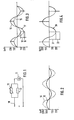
- a conventional phase control unit 12 for stepless speed adjustment of the motor is arranged in the supply branch 10 of a single-phase AC motor 11 which is of no particular interest here in terms of its construction, and in parallel with it a known throttle 13 is connected to the power consumption of the Motor-coordinated performance data, the design of which determines the minimum speed of the motor with completely ineffective phase control.
- the voltage applied to the motor 11 when the phase angle control is ineffective shows the voltage curve 15 in FIG. 2, whereas the unaffected mains voltage shows the voltage curve 16.
- the voltage curve 15 in FIG. 2, determined solely by the choke connected in parallel with the control device 12, is purely sinusoidal with amplitudes flattened relative to the mains voltage according to the voltage curve 16.
- the voltage curve 15 in this respect corresponds to the voltage curve 16 representing the mains voltage
- extremely smooth motor running is guaranteed at a minimum speed and the magnetic losses which may occur in the throttle 13 are small
- the motor operation with a speed that is higher than the minimum speed is characterized by the solid curve 17 in FIG. 3, in which the voltage curve 15 corresponding to the base load at minimum speed and the voltage curve 16 corresponding to the mains voltage are shown in thin dash lines.
- the voltage curve 17 runs identically with the voltage curve 15 over part of each half-wave, in order then to rise to the mains voltage according to the voltage curve 16 as a result of phase angle control at 18.
- the phase control only switches from the base load given by the voltage curve 15 to the mains voltage and thus by a reduced voltage compared to the pure phase control without a choke connected in parallel to the control unit.
- induction voltage peaks occur, which are indicated in FIG. 3 at 19.
- the voltage curve 20 drawn in full lines in FIG. 4, illustrates the motor operation with pure leading edge control, that is to say without a throttle connected in parallel with the control unit.
- the phase gating points are selected at the same time as in FIG. 3.
- the voltage increase from the amount 0 to the mains voltage is indicated. It can be seen that the voltage is much greater jump occurs when switching from the base load characterized by the voltage curve 15 to the mains voltage. In view of this increased voltage jump, substantially larger induction voltage peaks occur in pure phase control, which are denoted by 22 in FIG. 4.
Landscapes
- Engineering & Computer Science (AREA)
- Power Engineering (AREA)
- Control Of Ac Motors In General (AREA)
- Control Of Multiple Motors (AREA)
- Ac-Ac Conversion (AREA)
Abstract
Description
- Die Erfindung betrifft eine Einrichtung zur Drehzahlsteuerung bei Wechsel- und Drehstrommotoren mit einem nach dem Prinzip der Phasenanschnittsteuerung oder einem anderen elektronisch arbeitenden Steuergerät im Versorgungskreis des hinsichtlich seiner Drehzahl zu regelnden Motors.
- Die Steuerung der Drehzahl von Wechselstrom- und Drehstrommotoren mit Hilfe der Phasenanschnittsteuerung ist allgemein bekannt, aber mit einigen Unzulänglichkeiten behaftet, die der Anwendung häufig entgegenstehen. So treten infolge des zweifachen Anschnittes einer jeden Sinuswelle erhebliche Induktions-Spannungspitzen mit doppelter Netzfrequenz auf, die ein höchst unerwünschtes Motorbrummen verursachen. Auch wirken die durch die Phasenanschnitte verursachten Spannungsspitzen auf das Netz zurück und können der Netzfrequenz als Oberwellen überlagert werden. Naturgemäß kann dies zu starken Störeffekten bei Rundfunk- und Fernsehempfängern führen und sehr aufwendige Entstörungsmaßnahmen erforderlich machen. Schließlich wurde aber auch eine nicht unbeachtliche thermische Belastung bei Motoren mit Drehzahlveränderung mittels Phasenanschnittsteuerung festgestellt. .
- Das Ziel der vorliegenden Erfindung besteht daher in der Verbesserung der vorbekannten Phasenanschnittsteuerung zur Drehzahleinstellung bei Wechsel- oder Drehstrommotoren und insbesondere soll eine gegenüber dem Stande der Technik verbesserte Einrichtung für diesen Zweck geschaffen werden. Diese Aufgabe ist erfindungsgemäß dadurch gelöst, daß bei einer Einrichtung nach dem Oberbegriff des Patentanspruchs 1 in Parallelschaltung zu dem Steuergerät ein spannungsminderndes Schaltelement im Motor-Versorgungskreis angeordnet ist.
- Angesichts des in Parallelschaltung zu dem nach dem Prinzip der Phasenanschnittsteuerung oder einem anderen elektronisch arbeitenden Steuergerät liegenden Schaltelements, bei dem es sich in zweckmäßiger Ausgestaltung der Erfindung um eine Drossel, einen Kondensator oder, bei geringen Motorleistungen, auch um einen Widerstand handeln kann, findet bei der eingestellten Mindestdrehzahl des Motors dessen Spannungsversorgung ohne jeden Phasenanschnitt allein über das spannungsmindernde Schaltelement statt, wobei keine Änderung des sinusförmigen Spannungsverlaufs, sondern lediglich eine Reduzierung der Spannungsamplituden eintritt. Dies hat einen äußerst ruhigen Motorlauf zur Folge und die bei Verwendung einer Drossel oder eines spannungsfesten Kondensators als spannungsminderndes Schaltelement auftretenden Energieverluste sind vernachlässigbar gering. Erst beim Steuern der Drehzahl über die von demEpannungsmindernden. Schaltelement vorgegebene Mindestdrehzahl hinaus findet ein Phasenanschnitt statt, der jedoch darum im Vergleich zur herkömmlichen Phasenanschnittsteuerung nur geringe Induktions-Spannungsspitzen auslösen kann, weil von der durch das spannungsmindernde Schaltelement vorgegebenen Grundlast aus geschaltet wird. Ein ruhiger Motorlauf auch im Drehzahl-Verstellbereich ist die Folge. Darüber hinaus sind im Vergleich zu der reinen Phasenanschnittsteuerung die Geräuschentfaltung und die thermische Belastung der Motoren erheblich reduziert sowie ein geringerer Entstörungsaufwand erforderlich, eben weil nur die Differenz zwischen der Grundlast und der vollen Netzspannung geschaltet wird.
- Selbstverständlich können erfindungsgemäße Einrichtungen zur Drehzahlsteuerung bei Wechselsstrommotoren und Drehstrommotoren Verwendung finden, wobei im Falle von Drehstromantrieben in jeder Phase des Motor-Versorgungskreises ein spannungsminderndes Schaltelement angeordnet ist.
- Nachstehend soll eine Ausführungsform der Erfindung anhand der beigefügten Zeichnung näher erläutert werden. In schematischen Ansichten zeigen:
- Fig. 1 in einem Schaltbild die Anwendung der Erfindung auf einen Einphasen-Wechselstrommotor mit einer in Parallelschaltung zu einem Steuergerät zur Phasenanschnittsteuerung im Motor-Versorgungskreis angeordneten Drossel,
- Fig. 2 den Verlauf der am Motor anliegenden Spannung bei Mindestdrehzahl, also bei Spannungsversorgung des Motors allein über die Drossel, und im Vergleich dahzu den Verlauf der Netzspannung,
- Fig. 3 den Verlauf der am Motor anliegenden Spannung bei wirksamer Phasenanschnittsteuerung mit zu dem Steuergerät parallel geschalteter Drossel und
- Fig. 4 die bei reiner Phasenanschnittsteuerung am Motor anliegende Spannung und die auftretenden Induktions-Spannungsspitzen.
- Bei der Schaltung nach Fig. 1 ist im Versorgungszweig 10 eines hinsichtlich seines Aufbaues im einzelnen hier nicht interessierenden Ein-Phasenwechselstrommotors 11 ein herkömmliches Phasenanschnitt-Steuergerät 12 zur stufenlosen Drehzahleinstellung des Motors angeordnet und in Parallellage dazu liegt eine bekannte Drossel 13 mit auf die Leistungsaufnahme des Motors abgestimmten Leistungsdaten, deren Auslegung die Mindestdrehzahl des Motors bei völlig unwirksamer Phasenanschnittsteuerung bestimmt. Die bei wirkungsloser Phasenanschnittsteuerung am Motor 11 anliegende Spannung zeigt die Spannungskurve 15 in Fig. 2, hingegen die unbeeinflußte Netzspannung die Spannugskurve 16.
- Die allein durch die parallel zu dem Steuergerät 12 geschaltete Drossel bestimmte Spannungskurve 15 in Fig. 2 ist rein sinusförmig bei gegenüber der Netzspannung nach der Spannungskurve 16 abgeflachten Amplituden. Angesichts des rein sinusförmigen Verlaufs der Spannungskurve 15, die insoweit mit der die Netzspannung repräsentierenden Spannungskurve 16 übereinstimmt, ist ein extrem ruhiger Motorlauf bei Mindestdrehzahl gewährleistet und die in der Drossel 13 allenfalls auftretenden Ummagnetisierungsverluste sind klein
- Den Motorbetrieb mit gegenüber der Mindestdrehzahl erhöhter Drehzahl charakterisiert die in vollen Linien ausgezogene Spannungskurve 17 in Fig. 3, in der die der Grundlast bei Mindestdrehzahl entsprechende Spannungskurve 15 und die der Netzspannung entsprechende Spannungskurve 16 in dünnen Strichlinien eingetragen sind. Die Spannungskurve 17 verläuft über einen Teil einer jeden Halbwelle identisch mit der Spannungskurve 15, um dann infolge Phasenanschnittsteuerung bei 18 auf die Netzspannung gemäß der Spannungskurve 16 anzusteigen. Die Phasenanschnittsteuerung schaltet mithin lediglich von der durch die Spannungskurve 15 gegebenen Grundlast auf die Netzspannung und mithin um einen gegenüber der reinen Phasenanschnittsteuerung ohne zum Steuergerät parallel geschalteter Drossel um einen reduzierten Spannungsbetrag. Beim Schalten von Grundlast auf Netzspannung treten Induktions-Spannungsspitzen auf, die in Fig. 3 bei 19 angedeutet sind.
- Die in vollen Linien ausgezogene Spannungskurve 20 in Fig. 4 veranschaulicht hingegen den Motorbetrieb bei reiner Phasenanschnittsteuerung, also ohne parallel zum Steuergerät geschalteter Drossel. Die Phasenanschnittpunkte sind zeitgleich wie in Fig. 3 gewählt. Bei 21 ist der Spannungsanstieg vom Betrage 0 auf die Netzspannung angedeutet. Es ist ersichtlich, daß dabei ein ungleich größerer Spannungssprung als beim Schalten von der durch die Spannungskurve 15 charakterisierten Grundlast auf Netzspannung eintritt. Angesichts dieses erhöhten Spannungssprunges treten bei reiner Phasenanschnittsteuerung auch wesentlich größere Induktions-Spannungsspitzen auf, die in Fig. 4 mit 22 bezeichnet sind.
- Angesichts der bei der erfindungsgemäßen Steuerung in den Schaltpunkten gegenüber reiner Phasenanschnittsteuerung reduzierten Spannungssprünge im jeweiligen Schaltpunkt ist ein vergleichsweise ruhiger Motorbe- trieb bei stark reduzierter Geräuschentfaltung gewährleistet. Da erfindungsgemäß auch die in den Schaltpunkten auftretenden Induktions-Spannungsspitzen 19 gegenüber den Induktions-Spannungsspitzen 22 bei reiner Phasenanschnittsteuerung stark reduziert sind, treten vergleichsweise geringe Rückwirkungen auf das Netz ein, was gleichbedeutend mit einer erheblichen Reduzierung von Störeinflüssen ist. Demgemäß sind bei der Erfindung Entstörmaßnahmen entbehrlich oder im Vergleich zum reinen Phasenanschnittbetrieb erheblich reduziert.
Claims (5)
dadurch gekennzeichnet,
daß in Parallelschaltung zu dem Steuergerät (12) ein spannungsminderndes Schaltelement (13) im Versorgungskreis (10) des Motors (11) angeordnet ist.
Priority Applications (1)
| Application Number | Priority Date | Filing Date | Title |
|---|---|---|---|
| AT84111862T ATE41573T1 (de) | 1983-12-01 | 1984-10-04 | Einrichtung zur drehzahlsteuerung bei wechselund drehstrommotoren. |
Applications Claiming Priority (2)
| Application Number | Priority Date | Filing Date | Title |
|---|---|---|---|
| DE3343434 | 1983-12-01 | ||
| DE19833343434 DE3343434A1 (de) | 1983-12-01 | 1983-12-01 | Einrichtung zur drehzahlsteuerung bei wechsel- und drehstrommotoren |
Publications (3)
| Publication Number | Publication Date |
|---|---|
| EP0143943A2 true EP0143943A2 (de) | 1985-06-12 |
| EP0143943A3 EP0143943A3 (en) | 1986-06-04 |
| EP0143943B1 EP0143943B1 (de) | 1989-03-15 |
Family
ID=6215733
Family Applications (1)
| Application Number | Title | Priority Date | Filing Date |
|---|---|---|---|
| EP84111862A Expired EP0143943B1 (de) | 1983-12-01 | 1984-10-04 | Einrichtung zur Drehzahlsteuerung bei Wechsel- und Drehstrommotoren |
Country Status (3)
| Country | Link |
|---|---|
| EP (1) | EP0143943B1 (de) |
| AT (1) | ATE41573T1 (de) |
| DE (2) | DE3343434A1 (de) |
Family Cites Families (4)
| Publication number | Priority date | Publication date | Assignee | Title |
|---|---|---|---|---|
| AT329690B (de) * | 1974-01-31 | 1976-05-25 | Uher Ag | Phasenanschnitt-drehzahlsteuerschaltung fur einen aus einem triac oder einem thyristorpaar bestehenden wechselstrom-halbleiterventilsteller zur speisung eines wechselstrommotors |
| US3906316A (en) * | 1974-04-17 | 1975-09-16 | Bodine Electric Company | Electric motor starting circuit |
| US4276506A (en) * | 1979-06-29 | 1981-06-30 | Chore-Time Equipment, Inc. | Motor control circuit |
| DE3367306D1 (en) * | 1982-07-13 | 1986-12-04 | Arid Electronic Ag | Method and device for controlling the rotation speed of a pump driving asynchronous motor |
-
1983
- 1983-12-01 DE DE19833343434 patent/DE3343434A1/de not_active Withdrawn
-
1984
- 1984-10-04 AT AT84111862T patent/ATE41573T1/de not_active IP Right Cessation
- 1984-10-04 DE DE8484111862T patent/DE3477325D1/de not_active Expired
- 1984-10-04 EP EP84111862A patent/EP0143943B1/de not_active Expired
Also Published As
| Publication number | Publication date |
|---|---|
| DE3343434A1 (de) | 1985-07-11 |
| DE3477325D1 (en) | 1989-04-20 |
| EP0143943B1 (de) | 1989-03-15 |
| EP0143943A3 (en) | 1986-06-04 |
| ATE41573T1 (de) | 1989-04-15 |
Similar Documents
| Publication | Publication Date | Title |
|---|---|---|
| DE3934139C2 (de) | Elektronische Steuerschaltung für einen bürstenlosen Gleichstrommotor | |
| DE69506612T2 (de) | Steuerschaltung für induktive Belastung | |
| EP0989666B1 (de) | System zur Drehzahlsteuerung von Wechselstrom-Motoren | |
| EP2178201B1 (de) | Verfahren und Steuersystem zum Umformen einer Speisewechselspannung in eine Verbraucher-Betriebsspannung mit einstellbarem Effektivwert | |
| EP2502342B1 (de) | Verfahren und schaltungsanordnung zur stromregelung bei motoren | |
| EP0179356A2 (de) | Verfahren und Einrichtung zur Regelung einer Drehfeldmaschine | |
| DE19843106A9 (de) | System zur Drehzahlsteuerung von Wechselstrom-Motoren | |
| EP0802617A2 (de) | Leistungselektronische Schaltungsanordnung | |
| DE2251292C3 (de) | Anordnung zur Drehzahlregelung eines kollektorlosen Gleichstrommotors | |
| WO2009015826A1 (de) | Verfahren zum ansteuern eines asynchronmotors | |
| DE69403730T2 (de) | Leistungs oder Geschwindigkeitssteuerung einer Last | |
| DE102012108869A1 (de) | "Thermodynamische Kreisprozessanlage" | |
| EP0143943A2 (de) | Einrichtung zur Drehzahlsteuerung bei Wechsel- und Drehstrommotoren | |
| DE4413802C2 (de) | Verfahren und Vorrichtung zum Steuern der Drehzahl eines elektrischen Dreiphasen-Asynchronmotors | |
| DE4241647C1 (de) | Verfahren der Vektormodulation für die Ansteuerung eines Pulswechselrichters | |
| DE19536148A1 (de) | Leistungssteuerung für elektrisch betriebene Heizungspumpen | |
| DE3110308A1 (de) | Schaltungsanordnung zum drehzahlveraenderlichen ansteuern eines einphasen-induktionsmotors | |
| DE2804374A1 (de) | Spannungsregelkreis | |
| DE19942203B4 (de) | Verfahren zur Ausgangsspannungsbegrenzung für einen spannungs-/frequenzgeführten Umrichter | |
| DE3207262A1 (de) | Drehzahlsteuerschaltung fuer einen ventilatormotor, insbesondere in einer dunsthaube | |
| EP0456854B1 (de) | Verfahren und Vorrichtung zur Steuerung eines dreiphasigen Pulswechselrichters | |
| WO1991005401A1 (de) | Verfahren und vorrichtung zum regeln und steuern von wechselspannungen ab dem öffentlichen verteilernetz | |
| DE4034520A1 (de) | Verfahren und einrichtung zur einstellung des ausgangsseitigen sternspannungs-raumzeigers eines dreiphasigen, selbstgefuehrten und symmetrisch belasteten gleichspannungs-drehstrom-wechselrichters | |
| DE2730984C3 (de) | Stromrichterschaltung | |
| EP0930698B1 (de) | Verfahren und System zur Drehzahlsteuerung von elektronisch kommutierten Gleichstrommotoren |
Legal Events
| Date | Code | Title | Description |
|---|---|---|---|
| PUAI | Public reference made under article 153(3) epc to a published international application that has entered the european phase |
Free format text: ORIGINAL CODE: 0009012 |
|
| AK | Designated contracting states |
Designated state(s): AT BE CH DE FR GB IT LI LU NL SE |
|
| PUAL | Search report despatched |
Free format text: ORIGINAL CODE: 0009013 |
|
| AK | Designated contracting states |
Kind code of ref document: A3 Designated state(s): AT BE CH DE FR GB IT LI LU NL SE |
|
| 17P | Request for examination filed |
Effective date: 19860702 |
|
| 17Q | First examination report despatched |
Effective date: 19871020 |
|
| GRAA | (expected) grant |
Free format text: ORIGINAL CODE: 0009210 |
|
| AK | Designated contracting states |
Kind code of ref document: B1 Designated state(s): AT BE CH DE FR GB IT LI LU NL SE |
|
| PG25 | Lapsed in a contracting state [announced via postgrant information from national office to epo] |
Ref country code: NL Effective date: 19890315 Ref country code: IT Free format text: LAPSE BECAUSE OF FAILURE TO SUBMIT A TRANSLATION OF THE DESCRIPTION OR TO PAY THE FEE WITHIN THE PRESCRIBED TIME-LIMIT;WARNING: LAPSES OF ITALIAN PATENTS WITH EFFECTIVE DATE BEFORE 2007 MAY HAVE OCCURRED AT ANY TIME BEFORE 2007. THE CORRECT EFFECTIVE DATE MAY BE DIFFERENT FROM THE ONE RECORDED. Effective date: 19890315 Ref country code: BE Effective date: 19890315 |
|
| REF | Corresponds to: |
Ref document number: 41573 Country of ref document: AT Date of ref document: 19890415 Kind code of ref document: T |
|
| REF | Corresponds to: |
Ref document number: 3477325 Country of ref document: DE Date of ref document: 19890420 |
|
| GBT | Gb: translation of ep patent filed (gb section 77(6)(a)/1977) | ||
| ET | Fr: translation filed | ||
| NLV1 | Nl: lapsed or annulled due to failure to fulfill the requirements of art. 29p and 29m of the patents act | ||
| PG25 | Lapsed in a contracting state [announced via postgrant information from national office to epo] |
Ref country code: LU Free format text: LAPSE BECAUSE OF NON-PAYMENT OF DUE FEES Effective date: 19891031 |
|
| PLBE | No opposition filed within time limit |
Free format text: ORIGINAL CODE: 0009261 |
|
| STAA | Information on the status of an ep patent application or granted ep patent |
Free format text: STATUS: NO OPPOSITION FILED WITHIN TIME LIMIT |
|
| 26N | No opposition filed | ||
| PGFP | Annual fee paid to national office [announced via postgrant information from national office to epo] |
Ref country code: GB Payment date: 19930924 Year of fee payment: 10 |
|
| PGFP | Annual fee paid to national office [announced via postgrant information from national office to epo] |
Ref country code: SE Payment date: 19931018 Year of fee payment: 10 |
|
| PGFP | Annual fee paid to national office [announced via postgrant information from national office to epo] |
Ref country code: FR Payment date: 19931029 Year of fee payment: 10 Ref country code: AT Payment date: 19931029 Year of fee payment: 10 |
|
| PGFP | Annual fee paid to national office [announced via postgrant information from national office to epo] |
Ref country code: DE Payment date: 19931110 Year of fee payment: 10 |
|
| PGFP | Annual fee paid to national office [announced via postgrant information from national office to epo] |
Ref country code: CH Payment date: 19931229 Year of fee payment: 10 |
|
| PG25 | Lapsed in a contracting state [announced via postgrant information from national office to epo] |
Ref country code: GB Effective date: 19941004 Ref country code: AT Effective date: 19941004 |
|
| PG25 | Lapsed in a contracting state [announced via postgrant information from national office to epo] |
Ref country code: SE Effective date: 19941005 |
|
| PG25 | Lapsed in a contracting state [announced via postgrant information from national office to epo] |
Ref country code: LI Effective date: 19941031 Ref country code: CH Effective date: 19941031 |
|
| EAL | Se: european patent in force in sweden |
Ref document number: 84111862.3 |
|
| GBPC | Gb: european patent ceased through non-payment of renewal fee |
Effective date: 19941004 |
|
| PG25 | Lapsed in a contracting state [announced via postgrant information from national office to epo] |
Ref country code: FR Effective date: 19950630 |
|
| REG | Reference to a national code |
Ref country code: CH Ref legal event code: PL |
|
| PG25 | Lapsed in a contracting state [announced via postgrant information from national office to epo] |
Ref country code: DE Effective date: 19950701 |
|
| EUG | Se: european patent has lapsed |
Ref document number: 84111862.3 |
|
| REG | Reference to a national code |
Ref country code: FR Ref legal event code: ST |