EP0143961A1 - Vorrichtung zum Einhüllen von Gegenständen, insbesondere Zigaretten-Gruppen - Google Patents
Vorrichtung zum Einhüllen von Gegenständen, insbesondere Zigaretten-Gruppen Download PDFInfo
- Publication number
- EP0143961A1 EP0143961A1 EP84112558A EP84112558A EP0143961A1 EP 0143961 A1 EP0143961 A1 EP 0143961A1 EP 84112558 A EP84112558 A EP 84112558A EP 84112558 A EP84112558 A EP 84112558A EP 0143961 A1 EP0143961 A1 EP 0143961A1
- Authority
- EP
- European Patent Office
- Prior art keywords
- suction
- blank
- cutting cylinder
- bores
- material web
- Prior art date
- Legal status (The legal status is an assumption and is not a legal conclusion. Google has not performed a legal analysis and makes no representation as to the accuracy of the status listed.)
- Granted
Links
- 235000019504 cigarettes Nutrition 0.000 title claims abstract description 34
- 239000000463 material Substances 0.000 claims abstract description 34
- ATJFFYVFTNAWJD-UHFFFAOYSA-N Tin Chemical compound [Sn] ATJFFYVFTNAWJD-UHFFFAOYSA-N 0.000 claims abstract description 8
- 230000002093 peripheral effect Effects 0.000 claims description 33
- 238000012546 transfer Methods 0.000 claims description 7
- 238000004806 packaging method and process Methods 0.000 description 5
- 238000013461 design Methods 0.000 description 3
- 238000010586 diagram Methods 0.000 description 3
- 241000208125 Nicotiana Species 0.000 description 1
- 235000002637 Nicotiana tabacum Nutrition 0.000 description 1
- 230000001133 acceleration Effects 0.000 description 1
- 230000005540 biological transmission Effects 0.000 description 1
- 239000000969 carrier Substances 0.000 description 1
- 230000006835 compression Effects 0.000 description 1
- 238000007906 compression Methods 0.000 description 1
- 238000010276 construction Methods 0.000 description 1
- 239000000109 continuous material Substances 0.000 description 1
- 239000000428 dust Substances 0.000 description 1
- 238000003780 insertion Methods 0.000 description 1
- 230000037431 insertion Effects 0.000 description 1
- 238000012423 maintenance Methods 0.000 description 1
- 238000012856 packing Methods 0.000 description 1
- 239000002245 particle Substances 0.000 description 1
Images

Classifications
-
- B—PERFORMING OPERATIONS; TRANSPORTING
- B65—CONVEYING; PACKING; STORING; HANDLING THIN OR FILAMENTARY MATERIAL
- B65B—MACHINES, APPARATUS OR DEVICES FOR, OR METHODS OF, PACKAGING ARTICLES OR MATERIALS; UNPACKING
- B65B41/00—Supplying or feeding container-forming sheets or wrapping material
- B65B41/02—Feeding sheets or wrapper blanks
- B65B41/04—Feeding sheets or wrapper blanks by grippers
- B65B41/06—Feeding sheets or wrapper blanks by grippers by suction-operated grippers
-
- B—PERFORMING OPERATIONS; TRANSPORTING
- B65—CONVEYING; PACKING; STORING; HANDLING THIN OR FILAMENTARY MATERIAL
- B65B—MACHINES, APPARATUS OR DEVICES FOR, OR METHODS OF, PACKAGING ARTICLES OR MATERIALS; UNPACKING
- B65B19/00—Packaging rod-shaped or tubular articles susceptible to damage by abrasion or pressure, e.g. cigarettes, cigars, macaroni, spaghetti, drinking straws or welding electrodes
- B65B19/02—Packaging cigarettes
- B65B19/22—Wrapping the cigarettes; Packaging the cigarettes in containers formed by folding wrapping material around formers
- B65B19/228—Preparing and feeding blanks
Definitions
- the invention relates to a device for wrapping objects in a blank, in particular groups of cigarettes in a tin foil blank, which is separated from a material web in the area of a first endless conveyor (suction and cutting cylinder) and conveyed to a second endless conveyor (suction disks), wherein the blank is held at least on two lateral edge regions by the second endless conveyor in a plane transverse to the direction of transport of the object and can be laid around the object by pulling it off in a U-shape.
- a device of this type is the subject of DE-OS 29 06 204.
- a material web made of tinfoil or the like is fed to a suction and cutting cylinder which rotates continuously at a uniform speed.
- the individual blanks are separated from the material web by separating knives and fed to the suction disks as the subsequent second endless conveyor.
- the cigarette groups to be wrapped are conveyed between the suction disks, which are mounted at the same axis and at a distance from one another, a blank being placed in a U-shape around the front face of the cigarette group lying in the direction of transport.
- the cigarette group in this known device is inserted into a mouthpiece which is flush with the cigarette group on the front side in the transport direction and absorbs mechanical loads in the U-shaped wrapper.
- the suction discs are also driven to rotate continuously and uniformly, in coordination with the suction and cutting cylinders.
- the invention has for its object to further develop and improve devices of the above type or similar structure, in particular to increase performance, without affecting sensitive packaging goods, in particular cigarettes, by greater mechanical stress.
- the device according to the invention is characterized in that the suction and cutting cylinder (first endless conveyor) is continuously rotating and the suction disks (second endless conveyor) are cyclically driven in such a way that the cutting during a standstill phase of suction slices through the object (cigarette group) is removable from the suction discs.
- the first endless conveyor that is the suction and cutting cylinder
- the suction and cutting cylinder is driven at a relatively high rotational speed.
- their peripheral speed corresponds to that of the suction and cutting cylinder. Then, namely when the next cut is conveyed into the transfer area, the suction disks rotate at a correspondingly higher rotational speed.
- the material web (tinfoil) is fed continuously to the suction and cutting cylinder at a constant speed.
- the always constant conveying speed is significantly lower than the maximum rotational speed (peripheral speed) of the suction and Cutting cylinder.
- the front part of the material web lying against the jacket of the material web is slipped on, that is to say with relative movement to the suction and cutting cylinder.
- suction bores which are used for the corresponding fixation on the jacket of the suction and cutting turret.
- a special feature of the invention is therefore that the material web is fed at a constant speed, the severed cut by the first endless conveyor is then considerably accelerated, transferred to the rotating suction disks at a coordinated conveying speed and these are brought down to a current standstill. This sequence of movements enables noticeably higher performance.
- the device shown in the drawings is part of a packaging machine for cuboid objects, in particular cigarette groups 10. These are conveyed in succession and at a distance from one another along a straight (linear) packaging path 11.
- the cigarettes of the cigarette group 10 are oriented in the conveying direction.
- a blank 13 - in particular made of tinfoil - is folded in a U shape around the cigarette group 10, specifically as a result of entrainment of the blank 13 by an end face 14 of the cigarette group 10 lying forward in the direction of movement.
- the end face 14 detects the Blank 13 in a predetermined area, usually in the middle.
- the U-shaped wrapping takes place as a result of the insertion of the cigarette group 10 together with the blank 13 into a mouthpiece-like opening 15 of a further conveying path 16.
- the cigarette group 10 In order to protect the cigarette group 10 against undesired mechanical stress when the blank 13 is taken over, the cigarette group 10 is conveyed through a reciprocatingly driven mouthpiece 17. A sharp tapering leading edge 18 of the mouthpiece 17 lies at the moment of taking over the The blank 13 is essentially flush with the end face 14 of the cigarette group 10. Its upper, lower and lateral edges are thus protected by the mouthpiece 17 which is formed with an essentially closed cross section.
- the mouthpiece 17 is supported laterally outside the movement path of the cigarette groups 10 with transverse support legs 19 and a sliding body 20, to be precise in a reciprocating manner on lateral sliding rods 21.
- the coordinated reciprocating movement takes place by means of push rods 22 Mouthpiece drive 17.
- a continuous slot 24 is formed in the conveying direction.
- a conveying member namely a driver 25 of a chain conveyor 26 for the transport of the cigarette groups 10 in the region of the packaging web 11.
- the drivers 25, each of which detects a cigarette group 10 on its rear side, are attached to cross bars 27, which in turn are connected to side chains 28 are. Otherwise, the construction and mode of operation of the mouthpiece 17 and of the chain conveyor 26 correspond to the details of the device according to DE-OS 29 06 204.
- the blanks 13 are separated from a continuous material web 28, for example of tinfoil.
- the material web 28 is fed by a pair of pull rollers 29, 30 which are driven at a constant speed.
- the feed rate of the material web 28 is accordingly also constant, in such a way that it is exact within one work cycle a section of the material web 28 corresponding to the length of a blank 13 is provided.
- the material web 28 is fed to a suction and cutting cylinder 32 via deflection rollers 31.
- the material web 28 runs with a front part 33 approximately tangentially on the peripheral surface 34 of the suction and cutting cylinder 32.
- the further transport is now taken over by the rotating suction and cutting cylinder 32.
- the suction and cutting cylinder 32 is equipped with two separating knives 35 and 36.
- a cutting edge of the cutting knife 35 extends in the plane of the peripheral surface 34.
- This cutting knife 35 works together with a stationary counter knife 37, the cutting edge of which is arranged at such a small distance from the peripheral surface 34 of the suction and cutting cylinder 32 that the relative movement between Separating knife 35 and counter knife 37 cut the material web 28 and thus the blank 13 is produced.
- the counter knife 37 is arranged with respect to the position of the inflow of the material web 28 to the peripheral surface 34 such that, after the cut 13 has been cut off, a front part 33 which is sufficient to continue the transport of the material web 28 bears against the peripheral surface 34.
- the cut blank 13 is provided during the further transport by the suction and cutting cylinder 32 by means of the second cutting knife 36, which is set back with the cutting edge in relation to the peripheral surface 34, in the area of a knife roller 38 with a further cutting cut or a perforation cut, for example in the case of a tinfoil wrapping of the ziga rescue group 10 to define a flap.
- the rotatingly driven knife roller 38 is provided with a freely rotatable knife roller 39 which projects beyond the peripheral surface of the knife roller 38. This interacts with the cutting edge of the cutting knife 36 in such a way that the perforation cut can be carried out within the blank 13.
- the blank 13 is then transferred to suction disks 40, 41 as a second endless conveyor. These convey the blank 13 into the relative position to the packing web 11 already described for the transfer of the blank 13 to the cigarette group 10.
- the material web 28 or the blank 13 are held by suction on the peripheral surface 34 of the suction and cutting cylinder 32.
- suction bores open on the peripheral surface 34, several of which are each connected via an approximately radially directed connection bore 42 or 43 to axially or axially parallel collecting bores 44, 45. The latter open out in the region of a lateral end face 46 of the cutting and suction cylinder 32.
- distributor grooves 48 and 49 are formed in a fixed, that is to say not with rotating distributor disc 47. These each extend over a partial circumference of the suction and cutting cylinder 32 in accordance with the suction bores which are acted upon differently in different locations.
- the distributor grooves 48, 49 are connected to a central vacuum source (not shown).
- the distributor disk 47 is pressed against the end face 46 of the suction and cutting cylinder 32 by axially acting compression springs 50.
- connection bore 42a is assigned to a larger number of distributedly opening suction bores 51.
- the task of this multiplicity of suction bores 51 is, with a corresponding relative position of the suction and cutting cylinder 32 after cutting off the blank 13, to fix the front part 33 of the material web 28 sufficiently on the peripheral surface 34 in order to ensure further transport.
- the connection bore 42a is located with the associated collecting bore 44 in the region of the distributor groove 49.
- the suction bores 52 following counter to the direction of rotation of the suction and cutting cylinder 32 are also arranged in such a way that the part of the material web 28 conveyed on the peripheral surface 34 is reliably fixed.
- connection bores 43 which are assigned to the distributor groove 48, then follows in the circumferential direction - counter to the direction of rotation. It is also the task of the associated suction bores 53 to hold the material web 28 on the peripheral surface 34 (FIG. 1) when the suction bores 51 and 52 have been moved out of the area thereof. The suction bores 53 are then followed by a peripheral section of the suction and cutting cylinder 32 which is free of suction bores. The blank 13 extends in this area after it has been separated from the material web 28. The phase of the separating cut is shown in FIG. 3.
- the blank 13 is accordingly held in a region lying forward in the conveying direction by the suction bores 53 and in the rear region by a single, radially directed suction bore 54, which is assigned to the distributor groove 49 via a collecting bore 44.
- a single, radially directed suction bore 54 which is assigned to the distributor groove 49 via a collecting bore 44.
- several of the suction bores described above are arranged next to one another and distributed (FIG. 2).
- suction bores 53 are still operatively connected to the front region of the blank 13 when it is transferred to the suction disks 40, 41. After the blank 13 has been grasped by it, a peripheral region of the suction and cutting cylinder free of suction bores follows.
- the collecting bores 45 assigned to the suction bores 53 leave the area of the distributor groove 48.
- the suction bores 53 are thereby vented, and the holding force exerted on the blank 13 is accordingly eliminated.
- the collecting bores 45 as well as the collecting bores 44 enter the area of blow grooves 55 and 56, which are formed in the distributor disk 47 in the manner of the distributor grooves 48 and 49.
- the suction grooves 55 and 56 are connected to a compressed air source via a compressed air connection 57. In this area, the entire system of grooves and bores is cleaned of dust and tobacco particles by compressed air.
- the distributor grooves 48 and 49 enable an exact determination of the holding force for the mate due to their different design (diameter) and their position within the stationary distributor disc 47 rialbahn 28 and the blank 13.
- the partially overlapping distributor grooves 48 and 49 are connected by a radial connecting groove 58 to form a uniform suction channel system.
- the suction disks 40 and 41 are constructed in a similar manner. As can be seen in particular from FIG. 5, the suction disks 40 and 41 are each attached to a shaft end 59 and 60 in such a way that a transport space 61 remains approximately between them in the width of the cigarette group 10. This is conveyed between the suction disks 40, 41, the blank 13 held ready on the circumference of the suction disks 40, 41 being pulled off and taken along.
- suction disks 40, 41 which are designed in a corresponding manner, are likewise provided with suction bores 62 which open on the peripheral surfaces and are connected to collecting bores 63 which are parallel to the axis. These in turn open in the area of lateral end faces 64 in a distributor groove 65 of a distributor disk 66. This is furthermore formed with a blow groove 67.
- the distributor groove 65 ends below the transport plane of the cigarette group 10, so that an area of the blank 13 lying forward in the conveying direction is no longer held. This is the slipping pull of the zu section 13 of the suction discs 40, 41 relieved.
- the rear area of the blank 13, still associated with the peripheral surface 34 of the suction and cutting cylinder, is also free of suction air (FIG. 1) due to the design of the suction channel system in the suction and cutting cylinder 32.
- the drive of the conveying bodies described is of particular importance.
- the suction and cutting cylinder 32 rotates at a substantially higher peripheral speed V2 while maintaining the constant, uniform feed speed Y1 of the material web 28. This results in a relative movement between the material web 28 and the suction and cutting cylinder 32.
- a maintenance movement of the material web 28 on the peripheral surface 34 results in a slipping movement.
- this is conveyed as a result of the fixation on the peripheral surface 34 at the (higher) speed V2 of the suction and cutting cylinder 32 and thereby moves away from the front part 33 of the material web 28.
- This high acceleration of the blank makes it quick , short-term transfer to the suction discs 40, 41 enables.
- the peripheral speed of the suction and cutting cylinder 32 corresponds to that of the suction disks 40, 41.
- the feed speed V1 of the material web can be approximately 150 cm / sec, while the speed V2 is approximately 300 cm / sec.
- the suction disks 40 and 41 are driven discontinuously, i.e. intermittently.
- a special step mechanism 68 known in principle is provided.
- This consists of a driver 69 and a switching star 70.
- the former is driven continuously via a central shaft 71.
- Switching rollers 72 of the driver 69 enter the recesses of the switching star 70 one after the other.
- a peripheral region of the driver 69 is not equipped with such switching rollers 72.
- no rotation is transmitted despite the driver 69 rotating. This results in a non-uniform rotation of the switching star 70.
- the movement of the switching star 70 is transmitted to the suction disk 40, 41 via gear wheels 73 and 74.
- the standstill phase of the switching star 70 is otherwise fixed to the switching star 70 by support rollers 75, which temporarily rest on the outer circumference of the driver 69.
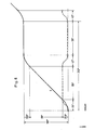
- FIG. 6 shows the movement characteristic of the driver in relation to that of the switching star in a diagram. It follows from this that a rotary movement takes place during a path of 180 ° of the switching star, while the switching star and thus the suction disks 40, 41 are at a standstill along the same angle of rotation or the same time period.
- the solid line of the diagram shows the time / distance ratio of the driver and the switching star, while the dashed line also shows the speed of the switching star in relation to the path of the driver.
- the drive through the central shaft 71 is transmitted via gear wheels 76, 77, 78, 79 and 80 to the suction and cutting cylinder 32 as well as to the knife roller 38 with a corresponding step-up or step-down ratio.
- the work cycle is due to the smaller distances between the supplied Ziga Rescue groups 10 from each other - due to the smaller distances between the carriers 25 - shorter than usual. Nevertheless, a more precise feeding of the blanks to the objects (cigarette groups) is possible due to the temporarily significantly higher conveying speed of the blanks and a standstill phase on the other hand.
Landscapes
- Engineering & Computer Science (AREA)
- Mechanical Engineering (AREA)
- Wrapping Of Specific Fragile Articles (AREA)
- Manufacturing Of Cigar And Cigarette Tobacco (AREA)
- Specific Conveyance Elements (AREA)
Abstract
Description
- Die Erfindung betrifft eine Vorrichtung zum Einhüllen von Gegenständen in einen Zuschnitt, insbesondere Gruppen von Zigaretten in einen Stanniol-Zuschnitt, der von einer Materialbahn im Bereich eines ersten Endlosförderers (Saug- und Schneidzylinder) abgetrennt und an einen zweiten Endlosförderer (Saugscheiben) weitergefördert wird, wobei der Zuschnitt wenigstens an zwei seitlichen Randbereichen durch den zweiten Endlosförderer in einer Ebene quer zur Transportrichtung des Gegenstands gehalten und unter Abziehen von diesem U-förmig um den Gegenstand herumlegbar ist. Eine Vorrichtung dieser Art ist Gegenstand der DE-OS 29 06 204. Eine Materialbahn aus Stanniol oder dgl. wird einem kontinuierlich mit gleichförmiger Geschwindigkeit umlaufenden Saug- und Schneidzylinder zugeführt. Auf dem Umfang desselben werden durch Trennmesser die einzelnen Zuschnitte von der Materialbahn abgetrennt und den Saugscheiben als nachfolgender zweiter Endlosförderer zugeführt. Zwischen den im Abstand voneinander gleichachsig gelagerten Saugscheiben werden die zu umhüllenden Zigaretten-Gruppen hindurchgefördert, wobei jeweils ein Zuschnitt U-förmig um die in Transportrichtung vornliegende Stirnfläche der Zigarettengruppe herumgelegt wird. Zum Schutz der Zigaretten wird die Zigarettengruppe bei dieser bekannten Vorrichtung in ein Mundstück eingeführt, welches an der in Transportrichtung vorderen Seite mit der Zigarettengruppe bündig abschließt und mechanische Belastungen bei der U-förmigen Umhüllung aufnimmt. Die Saugscheiben werden ebenfalls kontinuierlich und gleichförmig rotierend angetrieben, in Abstimmung mit dem Saug- und Schneidzylinder.
- Der Erfindung liegt die Aufgabe zugrunde, Vorrichtungen der vorstehenden Art oder ähnlichen Aufbaus weiter zu entwickeln und zu verbessern, insbesondere die Leistungsfähigkeit zu erhöhen, ohne empfindliche Verpackungsgüter, insbesondere Zigaretten, durch größere mechanische Beanspruchung zu beeinträchtigen.
- Zur Lösung dieser Aufgabe ist die erfindungsgemäße Vorrichtung dadurch gekennzeichnet, daß der Saug-und Schneidzylinder (erster Endlosförderer) kontinuierlich umlaufend und die Saugscheiben (zweiter Endlosförderer) taktweise angetrieben sind, derart, daß der Zuschnitt während einer Stillstandsphase der Saugscheiben durch den Gegenstand (Zigaretten-Gruppe) von den Saugscheiben abziehbar ist.
- Durch den momentanen Stillstand der Saugscheiben ist eine genauere Ausrichtung des Zuschnitts hinsichtlich der Relativlage auf den Gegenstand (Zigaretten-Gruppe) möglich. Des weiteren sind dadurch höhere Leistungen der Verpackungsmaschine erzielbar, indem die Abstände in der Zuführung der Gegenstände (Zigaretten-Gruppen) kleiner gewählt werden. Die Taktzeiten werden dadurch kürzer, ohne daß die Zigarettengruppen mit höherer Geschwindigkeit gefördert und dadurch erhöhten Belastungen ausgesetzt werden. Der momentane Stillstand der Saugscheiben ermöglicht überraschenderweise die kürzeren Taktzeiten, weil während der Bewegung, nämlich während der Zuförderung des Zuschnitts, mit höheren Geschwindigkeiten gearbeitet werden kann. Diese führen aber wegen der Stillstandsphase nicht zu einer ungenauen Relativlage des Zuschnitts.
- Nach einem weiteren Vorschlag der Erfindung wird der erste Endlosförderer, also der Saug- und Schneidzylinder, mit verhältnismäßig hoher Drehgeschwindigkeit angetrieben. Während der Übergabe eines Zuschnitts an die Saugscheiben entspricht deren Umfangsgeschwindigkeit derjenigen des Saug- und Schneidzylinders. Danach, nämlich bei der Förderung des nächsten Zuschnitts in den Übergabebereich, laufen die Saugscheiben mit entsprechend höherer Drehgeschwindigkeit um.
- Die Materialbahn (Stanniol) wird fortlaufend mit konstanter Geschwindigkeit dem Saug- und Schneidzylinder zugeführt. Die stets gleichbleibende Fördergeschwindigkeit ist deutlich geringer als die maximale Drehgeschwindigkeit (Umfangsgeschwindigkeit) des Saug- und Schneidzylinders. Der am Mantel desselben anliegende Vorderteil der Materialbahn wird schlupfend, also unter Relativbewegung zum Saug- und Schneidzylinder, weitergefördert. Sobald der Zuschnitt auf dem Saug-und Schneidzylinder von der Materialbahn abgetrennt ist, wird dieser mit der höheren Geschwindigkeit des genannten Zylinders weitertransportiert. Die schlupfende Relativbewegung der Materialbahn wird durch Saugbohrungen ermöglicht, die zur entsprechenden Fixierung auf dem Mantel des Saug- und Schneidrevolvers dienen.
- Eine Besonderheit der Erfindung besteht demnach darin, daß die Materialbahn mit einer konstanten Geschwindigkeit zugeführt, der abgetrennte Zuschnitt durch den ersten Endlosförderer sodann erheblich beschleunigt, bei abgestimmter Fördergeschwindigkeit an die umlaufenden Saugscheiben übergeben und diese auf momentanen Stillstand heruntergefahren werden. Dieser Bewegungsablauf ermöglicht eine merkbar höhere Leistung.
- Weitere Merkmale der Erfindung beziehen sich auf die Ausgestaltung der Endlosförderer sowie von Trennvorrichtungen.
- Ein Ausführungsbeispiel der Erfindung wird nachfolgend anhand der Zeichnungen näher erläutert. Es zeigen:
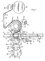
- Fig. 1 den wesentlichen Teil der Vorrichtung in schematischer Seitenansicht, teilweise im Längsschnitt,
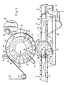
- Fig. 2 einen Querschnitt zu der Vorrichtung gemäß Fig. 1,
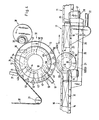
- Fig. 3 eine Ansicht entsprechend Fig. 1 ohne Schaltgetriebe bei veränderter Relativlage von Vorrichtungsteilen,
- Fig. 4 eine Darstellung entsprechend Fig. 3 bei nochmals veränderter Relativstellung,
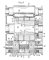
- Fig. 5 einen Ausschnitt der Fig. 2 in vergrößertem Maßstab,
- Fig. 6 ein Diagramm für die Bewegungscharakteristik innerhalb eines Arbeitstaktes.
- Die in den Zeichnungen dargestellte Vorrichtung ist Teil einer Verpackungsmaschine für quaderförmige Gegenstände, insbesondere Zigarettengruppen 10. Diese werden aufeinanderfolgend und mit Abstand voneinander längs einer geradlinigen (linearen) Packungsbahn 11 zugefördert. Die Zigaretten der Zigarettengruppe 10 sind dabei in Förderrichtung orientiert. Im Bereich einer Umhüllungsstation 12 wird ein quer zur Förderrichtung bereitgehaltener Zuschnitt 13 - insbesondere aus Stanniol - U-förmig um die Zigarettengruppe 10 herumgefaltet, und zwar infolge Mitnahme des Zuschnitts 13 durch eine in Bewegungsrichtung vornliegende Stirnseite 14 der Zigarettengruppe 10. Die Stirnseite 14 erfaßt den Zuschnitt 13 in einem vorgegebenen Bereich, üblicherweise in der Mitte. Durch die Weiterförderung der Zigarettengruppe 10 erfolgt die U-förmige Umhüllung infolge Einschubs der Zigarettengruppe 10 samt Zuschnitt 13 in eine mundstückartige Öffnung 15 einer Weiterförderbahn 16.
- Um die Zigarettengruppe 10 bei der Übernahme des Zuschnitts 13 gegen unerwünschte mechanische Belastung zu schützen, wird die Zigarettengruppe 10 durch ein hin- und hergehend angetriebenes Mundstück 17 hindurchgefördert. Eine scharf auslaufende Vorderkante 18 des Mundstücks 17 liegt im Moment der Übernahme des Zuschnitts 13 im wesentlichen bündig mit der Stirnseite 14 der Zigarettengruppe 10. Deren obere, untere und seitliche Kanten sind so durch das mit einem im wesentlichen geschlossenen Querschnitt ausgebildeten Mundstück 17 geschützt.
- Wie insbesondere aus Fig. 5 ersichtlich, ist das Mundstück 17 mit quergerichteten Tragschenkeln 19 und einem Gleitkörper 20 seitlich außerhalb der Bewegungsbahn der Zigarettengruppen 10 abgestützt, und zwar hin- und herbeweglich auf seitlichen Gleitstangen 21. Durch Schubstangen 22 erfolgt der abgestimmte hin- und hergehende Antrieb des Mundstücks 17.
- An der Unterseite des Mundstücks 17, nämlich in einer Bodenwandung 23 desselben, ist ein durchgehender Schlitz 24 in Förderrichtung gebildet. Dieser ermöglicht den Durchtritt eines Förderorgans, nämlich eines Mitnehmers 25 eines Kettenförderers 26 für den Transport der Zigarettengruppen 10 im Bereich der Packungsbahn 11. Die jeweils eine Zigarettengruppe 10 an ihrer Rückseite erfassenden Mitnehmer 25 sind an Querstangen 27 angebracht, die ihrerseits mit seitlichen Ketten 28 verbunden sind. Im übrigen entsprechen Aufbau und Arbeitsweise des Mundstücks 17 sowie des Kettenförderers 26 den Einzelheiten der Vorrichtung gemäß DE-OS 29 06 204.
- Die Zuschnitte 13 werden von einer fortlaufenden Materialbahn 28, z.B. aus Stanniol, abgetrennt. Die Materialbahn 28 wird durch ein Paar von Zugwalzen 29, 30 zugefördert, die mit konstanter Geschwindigkeit angetrieben werden. Die Zufördergeschwindigkeit der Materialbahn 28 ist demnach ebenfalls konstant, und zwar derart, daß innerhalb eines Arbeitstaktes exakt ein der Länge eines Zuschnitts 13 entsprechender Abschnitt der Materialbahn 28 zur Verfügung gestellt wird.
- Die Materialbahn 28 wird über Umlenkwalzen 31 einem Saug-und Schneidzylinder 32 zugeführt. Die Materialbahn 28 läuft mit einem Vorderteil 33 etwa tangential auf die Umfangsfläche 34 des Saug- und Schneidzylinders 32 auf. Der weitere Transport wird nun durch den umlaufenden Saug- und Schneidzylinder 32 übernommen.
- Der Saug- und Schneidzylinder 32 ist mit zwei Trennmessern 35 und 36 ausgerüstet. Eine Schneidkante des Trennmessers 35 erstreckt sich in der Ebene der Umfangsfläche 34. Dieses Trennmesser 35 wirkt zusammen mit einem ortsfesten Gegenmesser 37, dessen Schneidkante mit einem so geringen Abstand von der Umfangsfläche 34 des Saug- und Schneidzylinders 32 angeordnet ist, daß bei der Relativbewegung zwischen Trennmesser 35 und Gegenmesser 37 die Materialbahn 28 durchtrennt und somit der Zuschnitt 13 hergestellt wird.
- Das Gegenmesser 37 ist in bezug auf die Stelle des Zulaufs der Materialbahn 28 an die Umfangsfläche 34 so angeordnet, daß nach dem Abtrennen des Zuschnitts 13 ein für die Fortsetzung des Transports der Materialbahn 28 ausreichender Vorderteil 33 an der Umfangsfläche 34 anliegt.
- Der abgetrennte Zuschnitt 13 wird während des Weitertransports durch den Saug- und Schneidzylinder 32 durch das mit der Schneidkante gegenüber der Umfangsfläche 34 zurückgesetzte zweite Trennmesser 36 im Bereich einer Messerwalze 38 mit einem weiteren Trennschnitt bzw. einem Perforationsschnitt versehen, beispielsweise um bei einer Stanniolumhüllung der Zigarettengruppe 10 einen Flap zu definieren. Die rotierend angetriebene Messerwalze 38 ist mit einer frei drehbar gelagerten, über die Umfangsfläche der Messerwalze 38 hinwegragenden Messerrolle 39 versehen. Diese wirkt mit der Schneidkante des Trennmessers 36 zusammen, derart, daß der Perforationsschnitt innerhalb des Zuschnitts 13 ausgeführt werden kann.
- Der Zuschnitt 13 wird nun im weiteren Verlauf, nämlich im unteren Bereich des Saug- und Schneidzylinders 32, an Saugscheiben 40, 41 als zweitem Endlosförderer übergeben. Diese fördern den Zuschnitt 13 in die bereits beschriebene Relativstellung zur Packungsbahn 11 für die Übergabe des Zuschnitts 13 an die Zigarettengruppe 10.
- Die Materialbahn 28 bzw. der Zuschnitt 13 werden durch Ansaugen auf der Umfangsfläche 34 des Saug- und Schneidzylinders 32 gehalten. Zu diesem Zweck münden an der Umfangsfläche 34 Saugbohrungen, von denen jeweils mehrere über eine etwa radial gerichtete AnschluBbohrung 42 bzw. 43 mit axial bzw. achsparallel geführten Sammelbohrungen 44, 45 verbunden sind. Die letztgenannten münden im Bereich einer seitlichen Stirnfläche 46 des Schneid- und Saugzylinders 32. Korrespondierend zu den Mündungen der Sammelbohrungen 44, 45 sind in einer feststehenden, also nicht mit umlaufenden Verteilerscheibe 47 kreisbogenförmig ausgebildete Verteilernuten 48 und 49 gebildet. Diese erstrecken sich jeweils über einen Teilumfang des Saug-und Schneidzylinders 32 entsprechend den örtlich unterschiedlich beaufschlagten Saugbohrungen. Die Verteilernuten 48, 49 sind an eine zentrale Unterdruckquelle angeschlossen (nicht gezeigt). Die Verteilerscheibe 47 wird durch axial wirkende Druckfedern 50 an die Stirnfläche 46 des Saug- und Schneidzylinders 32 angedrückt.
- Die Saugbohrungen sind aufgrund der unterschiedlichen Funktionen ungleichförmig über die Umfangsfläche 34 des Saug- und Schneidzylinders 32 verteilt. Die Anschlußbohrung 42a ist einer größeren Anzahl von verteilt mündenden Saugbohrungen 51 zugeordnet. Aufgabe dieser Vielzahl von Saugbohrungen 51 ist es, bei entsprechender Relativstellung des Saug- und Schneidzylinders 32 nach Abtrennen des Zuschnitts 13 den Vorderteil 33 der Materialbahn 28 auf der Umfangsfläche 34 ausreichend zu fixieren, um den Weitertransport zu sichern. Die Anschlußbohrung 42a befindet sich dabei mit der zugeordneten Sammelbohrung 44 im Bereich der Verteilernut 49.
- Die entgegen der Drehrichtung des Saug- und Schneidzylinders 32 folgenden Saugbohrungen 52 sind ebenfalls so angeordnet, daß der auf der Umfangsfläche 34 geförderte Teil der Materialbahn 28 zuverlässig fixiert wird.
- Es folgt dann in Umfangsrichtung - entgegen der Drehrichtung - die Gruppe der Anschlußbohrungen 43, die der Verteilernut 48 zugeordnet sind. Aufgabe der hierzu gehörenden Saugbohrungen 53 ist es ebenfalls, die Materialbahn 28 auf der Umfangsfläche 34 zu halten (Fig. 1), wenn die Saugbohrungen 51 und 52 aus dem Bereich derselben bewegt worden sind. Auf die Saugbohrungen 53 folgt dann ein Umfangsabschnitt des Saug-und Schneidzylinders 32, der frei von Saugbohrungen ist. In diesem Bereich erstreckt sich der Zuschnitt 13, nachdem dieser von der Materialbahn 28 abgetrennt ist. Die Phase des Trennschnitts ist in Fig. 3 gezeigt. Der Zuschnitt 13 wird demnach in einem in Förderrichtung vornliegenden Bereich durch die Saugbohrungen 53 gehalten und im rückwärtigen Bereich durch eine einzelne, radialgerichtete Saugbohrung 54, die über eine Sammelbohrung 44 der Verteilernut 49 zugeordnet ist. In Axialrichtung des Saug- und Schneidzylinders sind jeweils mehrere der vorstehend beschriebenen Saugbohrungen nebeneinander und verteilt angeordnet (Fig. 2).
- Wie aus Fig. 4 ersichtlich, sind nur noch wenige Saugbohrungen 53 mit dem Vorderbereich des Zuschnitts 13 in Wirkverbindung, wenn dieser an die Saugscheiben 40, 41 übergeben wird. Nach Erfassen des Zuschnitts 13 durch diese folgt ein von Saugbohrungen freier Umfangsbereich des Saug- und Schneidzylinders.
- Im Bereich der unmittelbaren Übertragung des Zuschnitts 13 auf den Umfang der Saugscheiben 40, 41 verlassen die den Saugbohrungen 53 zugeordneten Sammelbohrungen 45 den Bereich der Verteilernut 48. Die Saugbohrungen 53 werden dadurch entlüftet, die auf den Zuschnitt 13 ausgeübte Haltekraft demnach aufgehoben.
- Bei Weiterbewegung des Saug- und Schneidzylinders 32 gelangen die Sammelbohrungen 45 ebenso wie die Sammelbohrungen 44 in den Bereich von Blasnuten 55 und 56, die nach Art der Verteilernuten 48 und 49 in der Verteilerscheibe 47 gebildet sind. Die Saugnuten 55 und 56 sind über einen Druckluftanschluß 57 mit einer Druckluftquelle verbunden. Das gesamte System der Nuten und Bohrungen wird in diesem Bereich durch Druckluft von Staub- und Tabakpartikeln gereinigt.
- Die Verteilernuten 48 und 49 ermöglichen aufgrund ihrer unterschiedlichen Gestaltung (Durchmesser) sowie ihrer Lage innerhalb der ortsfesten Verteilerscheibe 47 eine genaue Bestimmung der Haltekraft für die Materialbahn 28 und den Zuschnitt 13. Die einander zum Teil überlappenden Verteilernuten 48 und 49 sind durch eine radiale Verbindungsnut 58 zu einem einheitlichen Saugkanalsystem zusammengeschlossen.
- In ähnlicher Weise sind die Saugscheiben 40 und 41 aufgebaut. Wie insbesondere aus Fig. 5 ersichtlich, sind die Saugscheiben 40 und 41 jeweils an einem Wellenende 59 und 60 angebracht, derart, daß zwischen diesen ein Transportraum 61 etwa in der Breite der Zigarettengruppe 10 verbleibt. Diese wird zwischen den Saugscheiben 40, 41 hindurchgefördert, wobei der auf dem Umfang der Saugscheiben 40, 41 bereitgehaltene Zuschnitt 13abgezogen und mitgenommen wird.
- Die in übereinstimmenderweise ausgebildeten Saugscheiben 40, 41 sind zu diesem Zweck ebenfalls mit Saugbohrungen 62 versehen, die an den Umfangsflächen münden und mit achsparallelen Sammelbohrungen 63 verbunden sind. Diese wiederum münden im Bereich seitlicher Stirnflächen 64 in einer Verteilernut 65 einer Verteilerscheibe 66. Dieser ist weiterhin eine Blasnut 67 gebildet.
- Die Längs des Umfangs der Saugscheiben 40, 41 etwa mit gleichen Abständen voneinander angeordneten Saugbohrungen 62 wirken mit der sich längs eines Teilumfangs erstreckenden Verteilernut 65 so zusammen, daß die Saugbohrungen 62 im Bereich der Übernahme eines Zuschnitts 13 und der Weiterförderung bis in die Übergabeposition an die Zigarettengruppe 10 durch Saugluft ausreichend fixiert ist. Wie erkennbar, endet die Verteilernut 65 unterhalb der Transportebene der Zigarettengruppe 10, so daß ein in Förderrichtung vornliegender Bereich des Zuschnitts 13 nicht mehr gehalten wird. Dadurch ist das schlupfende Abziehen des Zuschnitts 13 von den Saugscheiben 40, 41 erleichtert. Auch der rückwärtige, noch der Umfangsfläche 34 des Saug- und Schneidzylinders zugeordnete Bereich des Zuschnitts 13 ist frei von Saugluft (Fig. 1) aufgrund der Ausgestaltung des Saugkanalsystems im Saug- und Schneidzylinder 32.
- Von besonderer Bedeutung ist der Antrieb der beschriebenen Förderorgane. Der Saug- und Schneidzylinder 32 läuft bei Aufrechterhaltung der konstanten, gleichförmigen Zufördergeschwindigkeit Y1 der Materialbahn 28 mit beträchtlich höherer Umfangsgeschwindigkeit V2 um. Dadurch ergibt sich eine Relativbewegung zwischen der Materialbahn 28 und dem Saug- und Schneidzylinder 32. Unter Aufrechterhaltung der Anlage der Materialbahn 28 an der Umfangsfläche 34 findet eine schlupfende Bewegung statt. Nach Abtrennen des Zuschnitts 13 wird dieser infolge der Fixierung auf der Umfangsfläche 34 mit der (höheren) Geschwindigkeit V2 des Saug- und Schneidzylinders 32 gefördert und entfernt sich dabei zunehmend von dem Vorderteil 33 der Materialbahn 28. Durch diese hohe Beschleunigung des Zuschnitts wird eine schnelle, kurzfristige Übergabe an die Saugscheiben 40, 41 ermöglicht. Während dieser Phase entspricht die Umfangsgeschwindigkeit des Saug- und Schneidzylinders 32 derjenigen der Saugscheiben 40, 41. Beispielsweise kann die Zufördergeschwindigkeit V1 der Materialbahn etwa 150 cm/sec betragen, während die Geschwindigkeit V2 etwa 300 cm/sec beträgt.
- Die Saugscheiben 40 und 41 werden diskontinuierlich, also taktweise, angetrieben. Zu diesem Zweck ist ein besonderes, prinzipiell aber bekanntes Schrittschaltgetriebe 68 vorgesehen. Dieses besteht aus einem Treiber 69 und einem Schaltstern 70. Ersterer wird über eine Zentralwelle 71 kontinuierlich angetrieben. Dabei treten nacheinander Schaltrollen 72 des Treibers 69 in Ausnehmungen des Schaltsterns 70 ein. Ein Umfangsbereich des Treibers 69 ist nicht mit derartigen Schaltrollen 72 bestückt. Während dieser Phase wird trotz Drehung des Treibers 69 keine Drehbewegung übertragen. Daraus ergibt sich eine ungleichförmige Drehung des Schaltsterns 70. Die Bewegung desselben wird über Zahnräder 73 und 74 auf die Saugscheibe 40, 41 weitergeleitet. Die Stillstandsphase des Schaltsterns 70 wird im übrigen durch Stützrollen 75 am Schaltstern 70 fixiert, die am Außenumfang des Treibers 69 zeitweilig anliegen.
- In Fig. 6 ist in einem Diagramm die Bewegungscharakteristik des Treibers im Verhältnis zu der des Schaltsterns wiedergegeben. Hieraus ergibt sich, daß während eines Weges von 180° des Schaltsterns eine Drehbewegung stattfindet, während längs eines gleichen Drehwinkels bzw. der gleichen Zeitdauer ein Stillstand des Schaltsterns und damit der Saugscheiben 40, 41 gegeben ist. Die ausgezogene Linie des Diagramms zeigt das Verhältnis Zeit/Weg von Treiber und Schaltstern, während die gestrichelte Linie die Geschwindigkeit des Schaltsterns ebenfalls im Verhältnis zum Weg des Treibers wiedergibt. Der Antrieb durch die Zentralwelle 71 wird über Zahnräder 76, 77, 78, 79 und 80 sowohl auf den Saug- und Schneidzylinder 32 als auch auf die Messerwalze 38 übertragen bei entsprechendem Über- oder Untersetzungsverhältnis.
- Bei der beschriebenen Vorrichtung ist der Arbeitstakt infolge der geringeren Abstände der zugeführten Zigarettengruppen 10 voneinander - aufgrund geringerer Abstände der Mitnehmer 25 - kürzer als üblich. Gleichwohl ist eine genauere Zuführung der Zuschnitte zu den Gegenständen (Zigarettengruppen) möglich infolge der zeitweilig erheblich höheren Fördergeschwindigkeit der Zuschnitte und einer Stillstandsphase derselben andererseits.
Claims (11)
Applications Claiming Priority (2)
| Application Number | Priority Date | Filing Date | Title |
|---|---|---|---|
| DE3340408 | 1983-11-09 | ||
| DE19833340408 DE3340408A1 (de) | 1983-11-09 | 1983-11-09 | Vorrichtung zum einhuellen von gegenstaenden, insbesondere zigaretten-gruppen |
Publications (2)
| Publication Number | Publication Date |
|---|---|
| EP0143961A1 true EP0143961A1 (de) | 1985-06-12 |
| EP0143961B1 EP0143961B1 (de) | 1988-01-27 |
Family
ID=6213782
Family Applications (1)
| Application Number | Title | Priority Date | Filing Date |
|---|---|---|---|
| EP84112558A Expired EP0143961B1 (de) | 1983-11-09 | 1984-10-18 | Vorrichtung zum Einhüllen von Gegenständen, insbesondere Zigaretten-Gruppen |
Country Status (6)
| Country | Link |
|---|---|
| US (1) | US4603534A (de) |
| EP (1) | EP0143961B1 (de) |
| JP (1) | JPH0620890B2 (de) |
| BR (1) | BR8405709A (de) |
| CA (1) | CA1305040C (de) |
| DE (2) | DE3340408A1 (de) |
Cited By (4)
| Publication number | Priority date | Publication date | Assignee | Title |
|---|---|---|---|---|
| EP0226872A3 (en) * | 1985-12-23 | 1988-03-23 | Focke & Co. (Gmbh & Co.) | Device for making (cigarette) packages from at least one foldable blank |
| EP0573944A1 (de) * | 1992-06-12 | 1993-12-15 | G.D Societa' Per Azioni | Zuführ- und Schneidevorrichtung für Wickelmaterial in einer Einwickelmaschine für Gegenstände |
| EP0629552A1 (de) * | 1993-06-18 | 1994-12-21 | G.D Societa' Per Azioni | Verfahren und Vorrichtung zum Beschicken einer Verpackungsstrasse mit Abschnitten von Wickelmaterial |
| EP0787648A3 (de) * | 1996-01-03 | 2000-03-29 | SASIB TOBACCO S.p.A. | Verpackungsmaschine,insbesondere für Zigaretten oder dergleichen |
Families Citing this family (12)
| Publication number | Priority date | Publication date | Assignee | Title |
|---|---|---|---|---|
| DE4411358B4 (de) * | 1994-03-31 | 2005-10-27 | Focke & Co.(Gmbh & Co. Kg) | Vorrichtung zum Herstellen von Verpackungen aus insbesondere dünner Kunststofffolie |
| DE19644079A1 (de) * | 1996-10-31 | 1998-05-07 | Focke & Co | Vorrichtung zum Herstellen von Verpackungen aus dünnem Verpackungsmaterial |
| DE19721144B4 (de) * | 1997-05-21 | 2006-04-20 | Focke & Co.(Gmbh & Co. Kg) | Verfahren und Vorrichtung zum Handhaben von Zuschnitten |
| DE19859949A1 (de) * | 1998-12-28 | 2000-06-29 | Focke & Co | Zigarettenpackung sowie Verfahren und Vorrichtung zum Herstellen derselben |
| DE102004012642A1 (de) * | 2004-03-12 | 2005-10-13 | Hauni Maschinenbau Ag | Vorrichtung und Verfahren zur Verpackung von Produkten der Tabak verarbeitenden Industrie |
| ITBO20050275A1 (it) * | 2005-04-22 | 2005-07-22 | Gd Spa | Macchina sovraincartatrice per pacchetti di sigarette |
| IT1394894B1 (it) | 2009-04-17 | 2012-07-20 | Gima Spa | Dispositivo per il confezionamento di un prodotto in un involucro |
| IT1394942B1 (it) | 2009-04-17 | 2012-07-27 | Gima Spa | Sistema per il confezionamento di sigarette in fogli ripiegati dotato di motori di controllo elettronici |
| DE102009044897A1 (de) | 2009-12-15 | 2011-06-16 | Krones Ag | Vorrichtung und Verfahren zum gruppenweisen Verpacken von Gegenständen |
| IT1399036B1 (it) * | 2010-01-26 | 2013-04-05 | Gima Spa | Convogliatore di incarto di una macchina impacchettatrice |
| DE102011113401A1 (de) * | 2011-09-16 | 2013-03-21 | Focke & Co. (Gmbh & Co. Kg) | Verfahren und Vorrichtung zum Herstellen von Zigaretten-Packungen |
| DE102011114522A1 (de) * | 2011-09-29 | 2013-04-04 | Focke & Co. (Gmbh & Co. Kg) | Verfahren und Vorrichtung zum Herstellen einer Verpackung für eine Gruppe rauchbarer Artikel |
Citations (1)
| Publication number | Priority date | Publication date | Assignee | Title |
|---|---|---|---|---|
| EP0015386A1 (de) * | 1979-02-17 | 1980-09-17 | FOCKE & CO. | Vorrichtung zum Einhüllen von Gegenständen, insbesondere Zigaretten-Gruppen |
Family Cites Families (10)
| Publication number | Priority date | Publication date | Assignee | Title |
|---|---|---|---|---|
| US2153483A (en) * | 1937-03-06 | 1939-04-04 | Rose Bros Gainsborough Ltd | Wrapping machine |
| US2860466A (en) * | 1956-05-08 | 1958-11-18 | Bellingham Steel Products Inc | Wrapping machines |
| DE1169361B (de) * | 1959-12-08 | 1964-04-30 | Hauni Werke Koerber & Co Kg | Verfahren und Vorrichtung zum Zufuehren von Huellmaterial zu einer Verpackungsbahn |
| DE1169835B (de) * | 1960-07-07 | 1964-05-06 | Hauni Werke Koerber & Co Kg | Verpackungsmaschine zum Einwickeln von Zigarettenpackungen |
| GB1037261A (en) * | 1962-03-08 | 1966-07-27 | Derek Henry Youngman | Improvements in or relating to the cutting of desired lengths from a web of wrapper material |
| GB1114708A (en) * | 1964-10-08 | 1968-05-22 | Wix Of London Ltd | Method and apparatus for packing and wrapping |
| CH491004A (de) * | 1968-05-28 | 1970-05-31 | Sig Schweiz Industrieges | Vorrichtung an einer Verpackungsmaschine zum Zuführen und Trennen eines Einschlagmaterialbandes |
| IT1001431B (it) * | 1973-12-20 | 1976-04-20 | Gd Spa | Dispositivo per alimentare materia le d incarto particolarmente mate riale in nastro avvolto in bobina del tipo cosiddetto floscio traspa rente alle macchine incartatrici con organo di strappo e di accom pagnamento alla posizione di uti lizzazione del foglio o spezzone precedentemente tagliato soltanto parzialmente |
| DE2407767C3 (de) * | 1974-02-19 | 1978-04-27 | Focke & Pfuhl, 3090 Verden | Verfahren und Vorrichtung zum Einschlagen von Zigarettengruppen o.dgl |
| GB1516522A (en) * | 1974-06-11 | 1978-07-05 | Focke Pfuhl Verpack Automat | Feeding groups of cigarettes |
-
1983
- 1983-11-09 DE DE19833340408 patent/DE3340408A1/de not_active Withdrawn
-
1984
- 1984-10-18 DE DE8484112558T patent/DE3469007D1/de not_active Expired
- 1984-10-18 EP EP84112558A patent/EP0143961B1/de not_active Expired
- 1984-10-30 US US06/666,516 patent/US4603534A/en not_active Expired - Lifetime
- 1984-11-02 CA CA000467005A patent/CA1305040C/en not_active Expired - Lifetime
- 1984-11-07 JP JP59233360A patent/JPH0620890B2/ja not_active Expired - Lifetime
- 1984-11-08 BR BR8405709A patent/BR8405709A/pt unknown
Patent Citations (1)
| Publication number | Priority date | Publication date | Assignee | Title |
|---|---|---|---|---|
| EP0015386A1 (de) * | 1979-02-17 | 1980-09-17 | FOCKE & CO. | Vorrichtung zum Einhüllen von Gegenständen, insbesondere Zigaretten-Gruppen |
Cited By (4)
| Publication number | Priority date | Publication date | Assignee | Title |
|---|---|---|---|---|
| EP0226872A3 (en) * | 1985-12-23 | 1988-03-23 | Focke & Co. (Gmbh & Co.) | Device for making (cigarette) packages from at least one foldable blank |
| EP0573944A1 (de) * | 1992-06-12 | 1993-12-15 | G.D Societa' Per Azioni | Zuführ- und Schneidevorrichtung für Wickelmaterial in einer Einwickelmaschine für Gegenstände |
| EP0629552A1 (de) * | 1993-06-18 | 1994-12-21 | G.D Societa' Per Azioni | Verfahren und Vorrichtung zum Beschicken einer Verpackungsstrasse mit Abschnitten von Wickelmaterial |
| EP0787648A3 (de) * | 1996-01-03 | 2000-03-29 | SASIB TOBACCO S.p.A. | Verpackungsmaschine,insbesondere für Zigaretten oder dergleichen |
Also Published As
| Publication number | Publication date |
|---|---|
| DE3469007D1 (en) | 1988-03-03 |
| CA1305040C (en) | 1992-07-14 |
| US4603534A (en) | 1986-08-05 |
| BR8405709A (pt) | 1985-09-10 |
| DE3340408A1 (de) | 1985-05-15 |
| JPS60123315A (ja) | 1985-07-02 |
| JPH0620890B2 (ja) | 1994-03-23 |
| EP0143961B1 (de) | 1988-01-27 |
Similar Documents
| Publication | Publication Date | Title |
|---|---|---|
| EP0143961B1 (de) | Vorrichtung zum Einhüllen von Gegenständen, insbesondere Zigaretten-Gruppen | |
| EP0071736B1 (de) | Verpackungs-Vorrichtung zum Herstellen von Zuschnitten und Zuführen derselben zu einer Verpackungsstation | |
| EP0312877B1 (de) | Verfahren und Vorrichtung zum Herstellen und Fördern von Packungs-Zuschnitten | |
| DE2407767C3 (de) | Verfahren und Vorrichtung zum Einschlagen von Zigarettengruppen o.dgl | |
| EP0109582B1 (de) | Vorrichtung zum Herstellen von Verpackungszuschnitten | |
| DE2350111A1 (de) | Schnellaufender bodenfaltungspacker | |
| EP0226872A2 (de) | Vorrichtung zum Herstellen von (Zigaretten-)Packungen aus mindestens einem faltbaren Zuschnitt | |
| DE2526047A1 (de) | Umlaufende foerdervorrichtung an einer einwickelmaschine | |
| EP0176789A2 (de) | Verfahren und Vorrichtung zum Wechseln von Bobinen in Verbindung mit Verpackungsmaschinen | |
| EP0304736B1 (de) | Verfahren und Vorrichtung zum Einhüllen von insbesondere Zigaretten-Packungen | |
| EP0015386A1 (de) | Vorrichtung zum Einhüllen von Gegenständen, insbesondere Zigaretten-Gruppen | |
| DE2711471A1 (de) | Vorrichtung zum einstellen und ausscheiden von verpackungsmaterialabschnitten (aus staniolpapier) in hochleistungs- zigarettenverpackungsmaschinen | |
| EP0133511B1 (de) | Vorrichtung zum Zuführen von Zuschnitten zu einer Verpackungsstation | |
| EP1013183B1 (de) | Vorrichtung zum Herumwickeln von Blättchen um stabförmige Gegenstände | |
| DE1235217B (de) | Packmaschine, insbesondere Zigarettenpackmaschine | |
| DE2217032C3 (de) | Vorrichtung zum Anbringen von aus einer fortlaufenden Bahn hergestellten Zuschnitten an Gegenständen | |
| EP0297266A2 (de) | Verfahren und Vorrichtung zum Zuführen von Verpackungs-Zuschnitten zu einem Faltaggregat | |
| EP0839719A1 (de) | Vorrichtung zum Herstellen von Verpackungen aus dünnem Verpackungsmaterial | |
| DE2244533A1 (de) | Packmaschine zum verpacken von aus stabfoermigen rauchartikeln bestehenden formationen | |
| EP0879761B1 (de) | Verfahren und Vorrichtung zum Handhaben von Zuschnitten | |
| DE602004011729T2 (de) | Verpackungsvorrichtung | |
| EP1890563A1 (de) | Rollung von stabförmigen rauchartikelgruppen | |
| DE2716391A1 (de) | Verfahren und vorrichtung zum herstellen und verpacken von filterzigaretten | |
| DE3515655A1 (de) | Verfahren und vorrichtung zum umhuellen von packungen mit huellmaterial | |
| DE69309157T2 (de) | Zuführ- und Schneidevorrichtung für Wickelmaterial in einer Einwickelmaschine für Gegenstände |
Legal Events
| Date | Code | Title | Description |
|---|---|---|---|
| PUAI | Public reference made under article 153(3) epc to a published international application that has entered the european phase |
Free format text: ORIGINAL CODE: 0009012 |
|
| AK | Designated contracting states |
Designated state(s): DE FR GB IT NL SE |
|
| 17P | Request for examination filed |
Effective date: 19850903 |
|
| 17Q | First examination report despatched |
Effective date: 19860207 |
|
| RAP1 | Party data changed (applicant data changed or rights of an application transferred) |
Owner name: FOCKE & CO. (GMBH & CO.) |
|
| GRAA | (expected) grant |
Free format text: ORIGINAL CODE: 0009210 |
|
| AK | Designated contracting states |
Kind code of ref document: B1 Designated state(s): DE FR GB IT NL SE |
|
| REF | Corresponds to: |
Ref document number: 3469007 Country of ref document: DE Date of ref document: 19880303 |
|
| ITF | It: translation for a ep patent filed | ||
| ET | Fr: translation filed | ||
| GBT | Gb: translation of ep patent filed (gb section 77(6)(a)/1977) | ||
| PLBE | No opposition filed within time limit |
Free format text: ORIGINAL CODE: 0009261 |
|
| STAA | Information on the status of an ep patent application or granted ep patent |
Free format text: STATUS: NO OPPOSITION FILED WITHIN TIME LIMIT |
|
| 26N | No opposition filed | ||
| PGFP | Annual fee paid to national office [announced via postgrant information from national office to epo] |
Ref country code: SE Payment date: 19910927 Year of fee payment: 8 |
|
| PGFP | Annual fee paid to national office [announced via postgrant information from national office to epo] |
Ref country code: FR Payment date: 19911007 Year of fee payment: 8 |
|
| ITTA | It: last paid annual fee | ||
| PG25 | Lapsed in a contracting state [announced via postgrant information from national office to epo] |
Ref country code: SE Effective date: 19921019 |
|
| PG25 | Lapsed in a contracting state [announced via postgrant information from national office to epo] |
Ref country code: FR Effective date: 19930630 |
|
| REG | Reference to a national code |
Ref country code: FR Ref legal event code: ST |
|
| PGFP | Annual fee paid to national office [announced via postgrant information from national office to epo] |
Ref country code: NL Payment date: 19931031 Year of fee payment: 10 |
|
| EUG | Se: european patent has lapsed |
Ref document number: 84112558.6 Effective date: 19930510 |
|
| PG25 | Lapsed in a contracting state [announced via postgrant information from national office to epo] |
Ref country code: NL Effective date: 19950501 |
|
| NLV4 | Nl: lapsed or anulled due to non-payment of the annual fee | ||
| REG | Reference to a national code |
Ref country code: GB Ref legal event code: IF02 |
|
| PGFP | Annual fee paid to national office [announced via postgrant information from national office to epo] |
Ref country code: GB Payment date: 20021016 Year of fee payment: 19 |
|
| PGFP | Annual fee paid to national office [announced via postgrant information from national office to epo] |
Ref country code: DE Payment date: 20021019 Year of fee payment: 19 |
|
| PG25 | Lapsed in a contracting state [announced via postgrant information from national office to epo] |
Ref country code: GB Free format text: LAPSE BECAUSE OF NON-PAYMENT OF DUE FEES Effective date: 20031018 |
|
| PG25 | Lapsed in a contracting state [announced via postgrant information from national office to epo] |
Ref country code: DE Free format text: LAPSE BECAUSE OF NON-PAYMENT OF DUE FEES Effective date: 20040501 |
|
| GBPC | Gb: european patent ceased through non-payment of renewal fee |
Effective date: 20031018 |