EP0144010A2 - Bicyclette - Google Patents
Bicyclette Download PDFInfo
- Publication number
- EP0144010A2 EP0144010A2 EP84113602A EP84113602A EP0144010A2 EP 0144010 A2 EP0144010 A2 EP 0144010A2 EP 84113602 A EP84113602 A EP 84113602A EP 84113602 A EP84113602 A EP 84113602A EP 0144010 A2 EP0144010 A2 EP 0144010A2
- Authority
- EP
- European Patent Office
- Prior art keywords
- seat
- bicycle according
- frame
- bracket
- rear wheel
- Prior art date
- Legal status (The legal status is an assumption and is not a legal conclusion. Google has not performed a legal analysis and makes no representation as to the accuracy of the status listed.)
- Withdrawn
Links
Images


Classifications
-
- B—PERFORMING OPERATIONS; TRANSPORTING
- B62—LAND VEHICLES FOR TRAVELLING OTHERWISE THAN ON RAILS
- B62K—CYCLES; CYCLE FRAMES; CYCLE STEERING DEVICES; RIDER-OPERATED TERMINAL CONTROLS SPECIALLY ADAPTED FOR CYCLES; CYCLE AXLE SUSPENSIONS; CYCLE SIDECARS, FORECARS, OR THE LIKE
- B62K3/00—Bicycles
- B62K3/02—Frames
Definitions
- the invention relates to a bicycle of the type corresponding to the preamble of claim 1.
- Such a bicycle corresponds to the classic construction, which has the so-called pentagonal frame.
- Such bicycles are also known with a smaller front wheel, more recently in particular as track racing bikes.
- the pentagonal frame (see the book by Rauck / Volke / Paturi "With the wheel through two centuries", second edition (1979), pages 113 to 117) is based on the framework principle and consists mainly of straight pipe sections that are joined at the nodes by sleeves.
- the pentagon comprises a front quadrilateral from a from the seat to the bottom bracket slightly obliquely forward leading, but rather steep stationary frame tube, the seat forward leading and the bottom bracket obliquely upwards leading frame tube and the Gabella formed by a tubular section g he exists, to which the frame tubes leading to the front are attached with their front ends.
- the fifth corner is formed by the rear wheel bearing, which is held by struts leading backwards from the bottom bracket and diagonally downwards from the seat.
- D is a bottom bracket only slightly in front of the seat and extending between the seat and bottom bracket frame tube is quite steep at an angle of about 7 0 ° to the vertical, the leg extends in contact virtually downward, in particular if the respective pedal crank is below and the leg is practically straight. To ensure that the pedal crank never touches the ground when driving, which can cause a fall, it must be installed at a certain height above the ground.
- the normal driving posture is a compulsory posture that deviates from any normal posture and represents another element of uncertainty.
- the invention has for its object a bicycle, which with regard to the presence of a frame tube leading from the seat to the bottom bracket, with regard to a deep and between the wheels at approximately the height of their hubs and with regard to the presence of normal sized wheels as The classic type is to be described in such a way that the driver takes a less unusual sitting posture and the causes of the feeling of insecurity at the start and when driving slowly are eliminated.
- a particularly important point is the fairly flat position of the main frame tube. It means that the bottom bracket is not essentially under, but considerably in front of the seat.
- the fact that at the same time the seat is not arranged in front of and under the upper vertex of the rear wheel (as in DE-OS 3o 2o 937) results in an increase in the distance from the seat to the pedal crank, which is an actuation the same with almost extended legs allowed.
- the legs do not run essentially downwards, as in the classic bicycle and also not almost horizontally as in the so-called recumbent bicycles, but in an overall orientation that extends diagonally forward and downward, which corresponds to a very natural sitting position, such as that of a person when sitting with outstretched legs on an armchair.
- the opposing forces to the pedaling forces are no longer applied by the weight of the driver and, in some cases, under heavy loads by holding on to the handlebars with the arms, but by means of support on the backrest.
- the seat with the backrest, the main frame tube and the pedal crank thus form a self-contained power system for driving the bicycle.
- the arms are much less involved in the generation of force for propulsion and mostly only have the function of steering.
- the upper body is positioned essentially upright because it is no longer necessary for the arms to extend downwards to generate any counter-forces. Rather, they can be guided forward in a relaxed, normal posture.
- the handlebar is raised accordingly.
- the seat is very close to the top of the rear wheel. Its height is no longer determined by the leg length, but the leg length can be accommodated to the front, ie with an essential horizontal component. The result is that the driver sitting on the seat can reach the ground with both legs without any effort and stands securely, and gains greater safety when driving slowly through the awareness of contact with the ground that can be reached at any time. The ground contact can also be maintained until a certain minimum speed is reached, so there are no wobbly start-up processes.
- the position of the seat can be changed relative to the bottom bracket according to claim 2. Because of the flat position of the main frame tube, however, such a change in position is accompanied by only a relatively small change in the height of the seat. The seat height that allows you to stand on the floor with both feet is not left.
- the backrest should essentially stand upright to form the best abutment against the pedaling forces.
- they can be adjustable at an angle of plus / minus 15 ° to the vertical (claim 3).
- a particularly effective adjustment type with regard to accommodating different leg lengths results from the rail guide according to claim 4.
- the embodiment according to claim 5 leads to a superimposed adjustment of the seat.
- the rail guide can be designed and arranged on the frame.
- the bracket can be bent in one piece in its tube section.
- the seat must be able to absorb the possibly considerable counterforce to the pedaling forces, and yet it must be possible to adjustably attach it to the bracket.
- the seat is no longer an actual saddle, because the legs do not lead downwards from the side of the seat, but extend forward from the seat.
- the seat therefore has more of an armchair function and can advantageously be embodied in the manner set out in claim 13.
- the seat shell is made of sheet metal or a hard plastic material and is anatomically shaped.
- the seat and the backrest should be at a slightly slightly more than right angle to each other, so that when the backrest is upright the seat is usually slightly inclined forward and downward.
- the seat should be quite short with a specified dimension of about 15o to 25o mm and beveled at the front edge from the center to the rear.
- the function of the seat according to the invention rests less in the interception of the driver's weight by merely resting on the seat surface than in the abutment against the pedaling forces. It is the contact pressure on the backrest that counts, through which part of the weight is absorbed by the friction on the backrest.
- the backrest is relatively high also contributes to this, in any case significantly higher than the length the seat, in particular about 1.5 to 2 times as high as the seat (claim 18).
- the frame can be designed in detail in the manner reproduced in claim 2o.
- a sleeveless frame with some of these features is known from DE-OS 31 43 265.
- the main frame tube that runs from the seat to the bottom bracket is missing and the subframes are completely endless, i.e. also in the area of the fork head.
- a comfortable reach is given when the handlebar grips are about the bottom bracket and about 25o mm to 4oo mm above the seat.
- the ride comfort can be further increased by Federun g s according to claim 24, if desired.
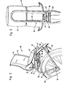
- the bicycle designated as a whole in FIG. 1 has a frame 1 0 which extends essentially in one plane and which has a continuous straight main frame tube 1 running from the seat 2o to the bottom bracket 8o, and subframes 2, 2 'arranged on both sides thereof. comprises, which are identical to each other.
- the subframes consist of an endlessly bent steel tube in the rear area, which is fastened at the front with its ends 3, 4 at the upper or lower end of the fork bearing 5 formed by a tube section, the connection being stabilized by an inserted reinforcing plate 6.
- the subframe 2 Starting from the upper end 3, the subframe 2 initially runs downward in a straight leg 7 and then merges in an arc 8 into a straight leg 9 which runs parallel to the main frame tube 1, rests laterally on this and is connected to it is.
- the legs 7, 9 form the upper frame spar, which is bent downward in a V-shape (FIG. 1), the legs 7, 9 forming an angle of approximately 120 ° and the arch 8 forming the apex of the "V".
- the bend 8 is, calculated from the upper end of the main frame tube 1, at about 3/5 its length.
- the leg 9 merges in an arc 11 into a straight strut 13 which extends obliquely at 45 ° to the rear and down to the rear wheel hub 12, which in an arc 14 extends in a straight line approximately horizontally to the front strut 15 extending up to the bottom bracket 8o.
- the radii of all arches are approximately 60 nm.
- the overall structure would correspond to a pentagonal frame. Because of the actually existing additional protruding corner on the arch 8, the frame could be called the hexagon frame
- the main frame tube 1 runs above the bottom bracket 80 and engages between the frame bars 16. Like the frame bars 15, 16, it is welded or soldered to the bottom bracket.
- the seat 2o is fixed on a support which consists of a bracket 21 formed in one piece from a tubular section.
- the bracket 21 is bent in a V-shape in the plane parallel to the frame or drawing plane and has on both sides of the rear wheel 22 extending straight legs 23, 23 ', which are pivotable at their front ends with screws 24 on the struts 13 approximately are placed in the middle.
- the legs 23, 26 form an angle of approximately 45 ° with one another in a plane parallel to the frame plane.
- the main frame tube 1 ends approximately at the level of the upper vertex of the rear wheel 22 in a clamping sleeve 28 which can be actuated by a clamping screw 29 and serves to fix a holding tube 3o which can be telescopically displaced in the main frame tube when the clamping screw 29 is loosened.
- a cross pin 31 (FIG. 2) is attached, which engages with its ends on the front ends of the legs 26.
- the bracket 21 tilts about the axis given by the position of the screws 24 and can in the different tilt positions Tightening the clamping screws 29 can be fixed.
- the legs 26 of the bracket 21 form a rail guide for the seat 2 0 .
- This includes a seat frame 32 which is an angle of about 9 0 ° to one another in the frame plane engaging frame portions 33,34 of two.
- the frame part 34 supports the seat 35, the frame part 33 the backrest 36.
- the frame parts 33, 34 in turn consist of tubular material. They are additionally braced against bending the right angle, so that the backrest 36 can form the desired abutment against the pedaling forces.
- the frame part 34 supporting the seat surface 35 rests on the legs 26 of the bracket 21 and engages under them with angle pieces 37 fastened to it and guided past the outside of the legs 26, which guide the frame part 34 and thus the seat 2o to the bracket such that only a shift in the longitudinal direction of the bicycle 1 00 is possible.
- the seat 2o does not automatically slip backwards under the pedaling forces, it can be fixed to the bracket 21 on the bracket 21 by means of a clamping piece 4o which extends in the transverse direction and engages with the ends 26 of the legs 26 on the bracket 21 and which is secured by a clamping screw 41 (FIG 3) can be pulled from below against the legs 26, which passes through a cross piece 42 in the connection area of the frame parts 33, 34 and is supported on the latter.
- the bracket 21 and thus the rail guidance of the seat 2o as a whole can be adjusted backwards and upwards and also the seat frame 32 on the bracket 21 in a substantially horizontal direction.
- the holding tube 3o there is also a certain influence on the angular position of the backrest 36, as will be explained with reference to FIGS. 4 to 6.
- a molded seat shell 43 made of hard plastic or sheet metal, which carries padding 44 on the front.
- the seat 2o could also be formed by an integral foam body that is dimensionally stable on the back and soft on the front. It is also possible, instead of the embodiment shown with a separate seat frame, to form the backrest 36, the seat surface 35 and the angle pieces 37 corresponding guide elements in one piece from a molded part made of plastic or an aluminum alloy.
- the padding 44 can be integrated into such a seat and, whether integrated or not, can also be inflatable.
- the seat 35 is relatively short from its foremost point in the middle to the point of intersection with the support surface of the backrest 36 and has a length 52 of only about 2oo mm.
- the backrest 36 is, however, relatively high and has a height 53 of approximately 35 mm in the exemplary embodiment. Decisive here are the parts of the seat 35 or the backrest 36 that come into contact, not the support structure. These parts also form an angle of approximately 95 °, indicated at 54, so that when the backrest 36 is upright, the seat 35 drops slightly towards the front.
- the seat is inclined 35 from the foremost point of towards both sides to the rear, so that the leading edges 35 ', 35 "form an angle of about 12 0 ° to each other.
- the width of the seat corresponds to the buttocks width and is located in the embodiment in Approximately 250 mm
- Both the seat 35 and the backrest 36 are essentially flat in the unloaded state at first approximation, but adapt to the body shape under load due to their resilience.
- the shortness of the seat 35 in combination with its front edges 35 receding outwards ', 35 " cause that the thigh is not hindered by the seat 35 when pedaling on its underside.
- the rear wheel 22 is driven in the usual way via the pedal cranks 38 and a chain 39.
- the front wheel 47 is also conventionally mounted in a fork 48 in the fork bearing 5.
- the handlebar grips 49 are attached approximately above the bottom bracket 8 0 , which is achieved, among other things, by a fairly strong inclination of the fork bearing 5.
- the steering axis is at an angle 5o to the horizontal of 62 °.
- the handlebars are pulled up so that the handlebar grips in the exemplary embodiment are located approximately 3oo mm above the seat surface 35 when this is compressed to its operating height under the weight of the driver.
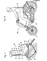
- Fig. 4 the holding tube 3o is shown in a middle extended position, which means that the frame part 33 forming a plane is almost vertical. Since the seat back 36 runs approximately parallel to the frame part 33, the position of the frame part 33 can be used to describe the position of the seat back 36.
- the seat frame 32 with the angle pieces 37 is in a central displacement position along the legs 26 of the bracket 21.
- the frame part 33 is around with respect to the vertical inclined at an angle 45 to the rear.
- the holding tube 3o is extended further than in FIG. 4. In FIG. 6, however, the holding tube 3o is almost completely pushed in, which results in a position of the backrest 36 or the frame part 33 that is slightly inclined forward by an angle 46.
- the construction is such that displacement angles 45, 45 of approximately 15 ° each are possible.
- the adjustment of the bracket 21 and the seat 2o according to FIGS. 4 to 6 not only results in a change in the position of the backrest 36 but also a not inconsiderable influence with regard to the distance to the bottom bracket 8 0 .
- the overall setting is made by a combined adjustment of the angular position of the bracket 21 and the position of the seat frame 32 along the same.
- the main frame tube 1 ends approximately at the height of the upper vertex of the rear wheel 22 and the legs 26 of the bracket 21 extend only a few centimeters above this vertex.
- the arrangement is such that when the driver sits on the seat 2o and the seat is correspondingly compressed, the vertical distance 6o between its lowest point and the vertex of the rear wheel 22 is not more than 100 mm.
- the seat 35 is therefore quite close above the upper vertex of the rear wheel 22.
- the total height of the seat 35 above the floor is therefore at a normal size of the rear wheel 22 a maximum of about 75o mm, so that the driver can still comfortably reach the floor with both legs .
- the main frame tube 1 is guided very flat to the front and makes an angle 7o with the horizontal, which is 32 ° in the exemplary embodiment.
- the pedal crank, the bottom bracket of which is located approximately at the level of the rear wheel hub 12 or the front hub 51 is located quite far forward with a distance in front of the rear wheel that is slightly larger than the radius of the rear wheel.
- the leg thus extends obliquely forwards and downwards, and as a result of the arrangement of the seat surface above the rear wheel 22 and the position of the bottom bracket 80 pulled far forward, the driver's thighs normally do not extend beyond the horizontal and the legs remain largely stretched.
- the sitting posture is shown in Fig. 8, which also clearly shows that the upper body remains almost upright when driving.
- the sitting position corresponds to a relaxed sitting position with legs stretched out on an armchair or a similar seat.
- the ground can be reached with both legs and feet fully up at any time.
- the connecting line given by the main frame tube 1 from the seat 2o to the bottom bracket 8 0 runs obliquely, ie at a flat angle to the horizontal and not essentially upright, as in the classic bicycle.
- the seat 2o can be arranged relatively low and close above the rear wheel 22.
- the seat 2o is not too low, however, so that the driver still has a certain height in order to keep an overview in traffic and to be recognized himself.
- the rear wheel 22 has a normal mm diameter on the order of about 6 00, wherein this dimension may vary by about 1 0% up or down, depending on whether it is apatirad or an adult bike.
- the front wheel 47 is slightly smaller than the rear wheel 22, so that the proportions given in Fig. 1 can be adhered to and closely overlying the front wheel 47 fork head 5 and the frame member 7 are so low that a comfortable and g e-propelled loose on - and descent is possible.
- the diameter of the front wheel 47 in the exemplary embodiment is approximately 82% of the diameter of the rear wheel 22 and can move approximately in the range from 70 to 85% of this diameter.
Landscapes
- Engineering & Computer Science (AREA)
- Mechanical Engineering (AREA)
- Automatic Cycles, And Cycles In General (AREA)
- Steering Devices For Bicycles And Motorcycles (AREA)
Applications Claiming Priority (2)
| Application Number | Priority Date | Filing Date | Title |
|---|---|---|---|
| AU2578/83 | 1983-11-28 | ||
| AU257883 | 1983-11-28 |
Publications (2)
| Publication Number | Publication Date |
|---|---|
| EP0144010A2 true EP0144010A2 (fr) | 1985-06-12 |
| EP0144010A3 EP0144010A3 (fr) | 1986-06-25 |
Family
ID=3693092
Family Applications (1)
| Application Number | Title | Priority Date | Filing Date |
|---|---|---|---|
| EP84113602A Withdrawn EP0144010A3 (fr) | 1983-11-28 | 1984-11-10 | Bicyclette |
Country Status (1)
| Country | Link |
|---|---|
| EP (1) | EP0144010A3 (fr) |
Cited By (2)
| Publication number | Priority date | Publication date | Assignee | Title |
|---|---|---|---|---|
| DE29710985U1 (de) * | 1997-06-24 | 1997-09-25 | Rambaum, Wolfgang, Dipl.-Ing., 22929 Schönberg | Fahrrad |
| EP0870672A1 (fr) * | 1997-04-08 | 1998-10-14 | Johann Hein | Bicyclette |
Family Cites Families (5)
| Publication number | Priority date | Publication date | Assignee | Title |
|---|---|---|---|---|
| AT139904B (de) * | 1933-02-21 | 1934-12-27 | Johann Hagen | Fahrrad mit Tretkurbelantrieb. |
| US2482472A (en) * | 1946-02-07 | 1949-09-20 | Fried Jack | Bicycle and frame and parts therefor |
| GB1018929A (en) * | 1964-10-19 | 1966-02-02 | Emil Friedmann | Improvements in and relating to pedal bicycles |
| DE3020937A1 (de) * | 1980-06-03 | 1981-12-10 | Manfred 4044 Kaarst Klutmann | Fahrrad |
| DE3143265A1 (de) * | 1980-11-21 | 1983-05-11 | Odo Prof. 5600 Wuppertal Klose | Fahrradrahmen |
-
1984
- 1984-11-10 EP EP84113602A patent/EP0144010A3/fr not_active Withdrawn
Cited By (2)
| Publication number | Priority date | Publication date | Assignee | Title |
|---|---|---|---|---|
| EP0870672A1 (fr) * | 1997-04-08 | 1998-10-14 | Johann Hein | Bicyclette |
| DE29710985U1 (de) * | 1997-06-24 | 1997-09-25 | Rambaum, Wolfgang, Dipl.-Ing., 22929 Schönberg | Fahrrad |
Also Published As
| Publication number | Publication date |
|---|---|
| EP0144010A3 (fr) | 1986-06-25 |
Similar Documents
| Publication | Publication Date | Title |
|---|---|---|
| EP2476607B2 (fr) | Trottinette pour petits enfants | |
| WO2014023291A1 (fr) | Bicyclette | |
| DE2437893A1 (de) | Fahrrad | |
| DE102011116213A1 (de) | Fahrradrahmen, Motorradrahmen | |
| EP0586754A1 (fr) | Cadres pour véhicules à voie unique, en particulière bicyclettes | |
| EP0144010A2 (fr) | Bicyclette | |
| DE29911911U1 (de) | Fahrrad | |
| DE202011004794U1 (de) | Klappsattel, Vorrichtung zum Halten u. Stützen des Körpers eines Radfahrers in einer aerodynamisch günstigen Fahrhaltung | |
| DE8432829U1 (de) | Fahrrad | |
| DE212008000106U1 (de) | Fahrrad- oder Trainingsradsitz | |
| DE102004033810B4 (de) | Fahrradtandem | |
| DE20000170U1 (de) | Fahrrad mit abgesenkter Sitzhöhe | |
| DE60018281T2 (de) | Fahrrad mit stützräder | |
| DE4324805C2 (de) | Fahrrad mit einem Tretkurbelantrieb | |
| DE4404994C2 (de) | Führungshilfe für ein Zweirad | |
| DE1035501B (de) | Kraftangetriebenes Zweirad | |
| DE202014001509U1 (de) | Lauffahrrad | |
| DE3906342A1 (de) | Brust- und sitzstuetzvorrichtung an fahrraedern | |
| DE9316154U1 (de) | Tretrad | |
| EP0870672A1 (fr) | Bicyclette | |
| DE3906601A1 (de) | Zweirad mit sicherheitsrahmen | |
| DE102011018876A1 (de) | Liegerad | |
| DE4027643A1 (de) | Fahrrad, bei dem der fahrer wie beim hochrad auf einem sitz hinter dem groesseren vorderrad vorne tritt und einen hinterradgabelschaft mit zwei lenkhebeln zum steuern ausschwenkt | |
| DE3423187A1 (de) | Fahrrad | |
| WO1985000567A1 (fr) | Cyclosiege |
Legal Events
| Date | Code | Title | Description |
|---|---|---|---|
| PUAI | Public reference made under article 153(3) epc to a published international application that has entered the european phase |
Free format text: ORIGINAL CODE: 0009012 |
|
| AK | Designated contracting states |
Designated state(s): AT BE CH DE FR GB IT LI NL |
|
| RTI1 | Title (correction) | ||
| PUAL | Search report despatched |
Free format text: ORIGINAL CODE: 0009013 |
|
| AK | Designated contracting states |
Kind code of ref document: A3 Designated state(s): AT BE CH DE FR GB IT LI NL |
|
| STAA | Information on the status of an ep patent application or granted ep patent |
Free format text: STATUS: THE APPLICATION IS DEEMED TO BE WITHDRAWN |
|
| 18D | Application deemed to be withdrawn |
Effective date: 19861229 |
|
| RIN1 | Information on inventor provided before grant (corrected) |
Inventor name: O'REILLY, BARRY |