EP0144040A2 - Dispositif de solidarisation de tronçons verticaux adjacents rapprochés de tubes d'un échangeur de chaleur à boucles - Google Patents
Dispositif de solidarisation de tronçons verticaux adjacents rapprochés de tubes d'un échangeur de chaleur à boucles Download PDFInfo
- Publication number
- EP0144040A2 EP0144040A2 EP84114067A EP84114067A EP0144040A2 EP 0144040 A2 EP0144040 A2 EP 0144040A2 EP 84114067 A EP84114067 A EP 84114067A EP 84114067 A EP84114067 A EP 84114067A EP 0144040 A2 EP0144040 A2 EP 0144040A2
- Authority
- EP
- European Patent Office
- Prior art keywords
- section
- welded
- sections
- beak
- tubes
- Prior art date
- Legal status (The legal status is an assumption and is not a legal conclusion. Google has not performed a legal analysis and makes no representation as to the accuracy of the status listed.)
- Granted
Links
Images

Classifications
-
- F—MECHANICAL ENGINEERING; LIGHTING; HEATING; WEAPONS; BLASTING
- F28—HEAT EXCHANGE IN GENERAL
- F28F—DETAILS OF HEAT-EXCHANGE AND HEAT-TRANSFER APPARATUS, OF GENERAL APPLICATION
- F28F9/00—Casings; Header boxes; Auxiliary supports for elements; Auxiliary members within casings
-
- F—MECHANICAL ENGINEERING; LIGHTING; HEATING; WEAPONS; BLASTING
- F22—STEAM GENERATION
- F22B—METHODS OF STEAM GENERATION; STEAM BOILERS
- F22B37/00—Component parts or details of steam boilers
- F22B37/02—Component parts or details of steam boilers applicable to more than one kind or type of steam boiler
- F22B37/10—Water tubes; Accessories therefor
- F22B37/20—Supporting arrangements, e.g. for securing water-tube sets
- F22B37/202—Suspension and securing arrangements for contact heating surfaces
-
- F—MECHANICAL ENGINEERING; LIGHTING; HEATING; WEAPONS; BLASTING
- F22—STEAM GENERATION
- F22B—METHODS OF STEAM GENERATION; STEAM BOILERS
- F22B37/00—Component parts or details of steam boilers
- F22B37/02—Component parts or details of steam boilers applicable to more than one kind or type of steam boiler
- F22B37/10—Water tubes; Accessories therefor
- F22B37/20—Supporting arrangements, e.g. for securing water-tube sets
-
- F—MECHANICAL ENGINEERING; LIGHTING; HEATING; WEAPONS; BLASTING
- F28—HEAT EXCHANGE IN GENERAL
- F28F—DETAILS OF HEAT-EXCHANGE AND HEAT-TRANSFER APPARATUS, OF GENERAL APPLICATION
- F28F9/00—Casings; Header boxes; Auxiliary supports for elements; Auxiliary members within casings
- F28F9/007—Auxiliary supports for elements
- F28F9/013—Auxiliary supports for elements for tubes or tube-assemblies
-
- Y—GENERAL TAGGING OF NEW TECHNOLOGICAL DEVELOPMENTS; GENERAL TAGGING OF CROSS-SECTIONAL TECHNOLOGIES SPANNING OVER SEVERAL SECTIONS OF THE IPC; TECHNICAL SUBJECTS COVERED BY FORMER USPC CROSS-REFERENCE ART COLLECTIONS [XRACs] AND DIGESTS
- Y10—TECHNICAL SUBJECTS COVERED BY FORMER USPC
- Y10S—TECHNICAL SUBJECTS COVERED BY FORMER USPC CROSS-REFERENCE ART COLLECTIONS [XRACs] AND DIGESTS
- Y10S165/00—Heat exchange
- Y10S165/355—Heat exchange having separate flow passage for two distinct fluids
- Y10S165/40—Shell enclosed conduit assembly
- Y10S165/401—Shell enclosed conduit assembly including tube support or shell-side flow director
- Y10S165/416—Extending transverse of shell, e.g. fin, baffle
Definitions
- the present invention relates to a device for securing adjacent vertical sections close to tubes of a heat exchanger forming loops between an inlet and an outlet by which they are suspended from a rigid structure.
- Document FR-A-1259288 has already proposed a device for securing adjacent tubes of an exchanger, comprising a male element welded to one of the two adjacent tubes, and two female elements welded to the other tube and coming to block the male element.
- Such devices are relatively complex. They require in the case of document FR-A-1259288 different parts of complex shapes, and in the case of document US-A-2809616 eight parts and six welding operations by junction device.
- the object of the present invention is to provide a device for securing the sections of vertical tubes which transfers the weight of the sections of the central part to the inlet and outlet sections, without however giving rise to stresses liable to produce deformations, cracks or weld breaks, but which is simple and quick to implement.
- each section is provided with a hollow element projecting on its side facing the outside of the bundle, welded to it according to two generatrices, coming from press on the external surface of the neighboring section, and having a beak oriented downwards, while the neighboring section is provided opposite an analogous element, also welded on it according to two generatrices, coming to bear on the external surface of the first section below the first element, and provided with an upwardly facing spout fitting into the spout of the first element.
- each section disposed on the inner side relative to the adjacent section with which it is secured is further provided with a cleat welded to its generatrix closest to the adjacent section below the lowest point of the hollow element , and at a sufficiently small distance from the height of the spouts to prevent the disengagement of the hollow elements for securing the two sections.
- the superheater element comprises three tubes in parallel, forming four loops 5, 6, 7, 8, the sections of inlet tubes shown in 1 being subject to a fixed structure 3 and the sections of tubes of outlet shown in 2 to a fixed structure 4.
- the securing device represented generally at 9, disposed in the upper part of the exchanger, comprises elements for securing adjacent sections, starting from the sections of the central loop, on the one hand to the left, on the other hand to the right, in order to transmit half the weight of the tubes to the inlet sections, and the other half to the outlet sections.
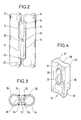
- FIGS. 2 and 3 show on a larger scale hollow elements for securing two adjacent tubes 10 and 11.
- the element 12 is welded to the tube section 10 by the weld beads 14 and 24. Its oblong internal opening comes into contact along the contour 16 with the adjacent section 11, and comprises a beak 18 oriented downwards, resting on the upper part of the element 13. The latter is welded to the section 11 by the weld beads 15 and 25. Its internal opening comes into contact with the section 10 along the contour 17, and has a beak 19 oriented upwards, pressing on the lower part of the element 12. The edges 20 of the spout 18 and 21 of the spout 19 appear in FIG. 3.
- a cleat 22 is welded to the tube 10, below the element 13, and close enough to the latter so that it cannot disengage from the element 12, given the height of their spouts 18 and 19.
- Figure 4 shows in perspective a fastening element before welding on a tube.
- Generally rectangular in shape it has two flat edges 26, 27, along which it is welded to the corresponding tube, separated by a depression 28 of circular shape and of radius equal to the radius of the tubes, so as to be applied to the tube, and on the other side two flat edges 29, 30, separated by a depression 31 also of circular shape and of the same radius, so as to come to be applied on the adjacent tube. It is also pierced with an oblong opening 32, and ends downwards with a spout 18.
Landscapes
- Engineering & Computer Science (AREA)
- Physics & Mathematics (AREA)
- Thermal Sciences (AREA)
- Mechanical Engineering (AREA)
- General Engineering & Computer Science (AREA)
- Heat-Exchange Devices With Radiators And Conduit Assemblies (AREA)
- Details Of Heat-Exchange And Heat-Transfer (AREA)
Abstract
Description
- La présente invention concerne un dispositif de solidarisation de tronçons verticaux adjacents rapprochés de tubes d'un échangeur de chaleur formant des boucles entre une entrée et une sortie par lesquelles ils sont suspendus à une structure rigide.
- En effet, dans de tels échangeurs, le poids des tronçons des tubes disposés dans la partie centrale entraînerait des déformations si ce poids n'était pas reporté sur les tronçons externes reliés à l'entrée et à la sortie. On a déjà proposé de transmettre leur poids en solidarisant rigidement tous les tronçons de tubes dans la zone la plus haute au moyen de petits éléments ronds ou carrés soudés entre les tronçons. Ce dispositif rigide est soumis à des contraintes résultant, outre le poids des tubes,
- - des différences de dilatation entre les diverses boucles, dont les températures moyennes sont différentes, du fait du réchauffage du fluide circulant dans l'échangeur de son entrée à sa sortie,
- - des vibrations pouvant survenir en fonctionnement,
- - de phénomènes de balancement des panneaux de tubes à l'intérieur de la chambre de combustion,
- - du retrait des soudures, celles-ci étant effectuées sur un ensemble rigide.
- Ces contraintes risquent d'entraîner des déformations et des fissurations ou même des ruptures de certaines soudures.
- Il a déjà été proposé dans le document FR-A- 1259288 un dispositif de solidarisation de tubes adjacents d'un échangeur, comprenant un élément mâle soudé sur l'un des deux tubes adjacents, et deux éléments femelles soudés sur l'autre tube et venant bloquer l'élément mâle.
- Il a aussi été proposé dans le document US-A- 2809616 un dispositif de solidarisation de tubes adjacents d'un échangeur, comprenant de chaque côté des deux tubes adjacents trois pièces de jonction, l'une à hauteur médiane soudée à l'un des tubes, et les deux autres disposées respectivement au-dessus et au-dessous de la première, soudées à l'autre tube. Ces pièces sont réunies par un goujon vertical qui les traverse.
- De tels dispositifs sont relativement complexes. Ils nécessitent dans le cas du document FR-A- 1259288 des pièces différentes de formes complexes, et dans le cas du document US-A- 2809616 huit pièces et six opérations de soudage par dispositif de jonction.
- La présente invention a pour but de procurer un dispositif de solidarisation des tronçons de tubes verticaux qui reporte le poids des tronçons de la partie centrale sur les tronçons d'entrée et de sortie, sans cependant entraîner de contraintes susceptibles de produire des déformations, fissurations ou ruptures de soudures, mais qui soit simple et de mise en oeuvre rapide.
- Le dispositif selon l'invention est caractérisé en ce qu'à partir des tronçons centraux, chaque tronçon est muni d'un élément creux en saillie sur son côté tourné vers l'extérieur du faisceau, soudé sur lui selon deux génératrices, venant s'appuyer sur la surface externe du tronçon voisin, et comportant un bec orienté vers le bas, cependant que le tronçon voisin est muni en regard d'un élément analogue, également soudé sur lui selon deux génératrices, venant s'appuyer sur la surface externe du premier tronçon au-dessous du premier élément, et muni d'un bec orienté vers le haut s'emboîtant avec le bec du premier élément.
- De préférence, chaque tronçon disposé du côté intérieur par rapport au tronçon adjacent avec lequel il est solidarisé est en outre muni d'un taquet soudé sur sa génératrice la plus proche du tronçon adjacent au-dessous du point le plus bas de l'élément creux, et à une distance suffisamment faible par rapport à la hauteur des becs pour empêcher le déboîtement des éléments creux de solidarisation des deux tronçons.
- Il est décrit ci-après à titre d'exemple et en référence aux figures du dessin annexé, un dispositif de solidarisation des tronçons verticaux voisins de tubes d'un élément de surchauffeur de vapeur pour chaudière.
-
- La figure 1 représente l'élément de surchauffeur en élévation.
- La figure 2 représente en élévation les éléments creux de solidarisation de deux tronçons voisins soudés sur ceux-ci et en prise l'un sur l'autre.
- La figure 3 représente les mêmes éléments en plan vus de dessus.
- La figure 4 représente en perspective un élément creux de solidarisation.
- Dans la figure 1, l'élément de surchauffeur comporte trois tubes en parallèle, formant quatre boucles 5, 6, 7, 8, les tronçons de tubes d'entrée représentés en 1 étant assujettis à une structure fixe 3 et les tronçons de tubes de sortie représentés en 2 à une structure fixe 4. Le dispositif de solidarisaion, représenté globalement en 9, disposé dans la partie supérieure de l'échangeur, comporte des éléments de solidarisation de tronçons adjacents, à partir des tronçons de la boucle centrale, d'une part vers la gauche, d'autre part vers la droite, afin de transmettre la moitié du poids des tubes aux tronçons d'entrée, et l'autre moitié aux tronçons de sortie.
- Les figures 2 et 3 représentent à plus grande échelle des éléments creux de solidarisation de deux tubes adjacents 10 et 11.
- L'élément 12 est soudé au tronçon de tube 10 par les cordons de soudure 14 et 24. Son ouverture interne oblongue vient au contact le long du contour 16 avec le tronçon adjacent 11, et comporte un bec 18 orienté vers le bas, reposant sur la partie supérieure de l'élément 13. Ce dernier est soudé au tronçon 11 par les cordons de soudure 15 et 25. Son ouverture interne vient au contact du tronçon 10 le long du contour 17, et présente un bec 19 orienté vers le haut, s'appuyant sur la partie inférieure de l'élément 12. Les arêtes 20 du bec 18 et 21 du bec 19 apparaissent sur la figure 3.
- Pour éviter toute possibilité de déboîtement des deux éléments de solidarisation, un taquet 22 est soudé sur le tube 10, au-dessous de l'élément 13, et suffisamment près de celui-ci pour qu'il ne puisse pas se déboîter de l'élément 12, compte tenu de la hauteur de leurs becs 18 et 19.
- La figure 4 représente en perspective un élément de solidarisation avant son soudage sur un tube. De forme générale rectangulaire, il comporte deux bords plans 26, 27, le long desquels il est soudé sur le tube correspondant, séparés par une dépression 28 de forme circulaire et de rayon égal au rayon des tubes, de façon à s'appliquer sur le tube, et de l'autre côté deux bords plans 29, 30, séparés par une dépression 31 également de forme circulaire et de même rayon, de façon à venir s'appliquer sur le tube adjacent. Il est percé en outre d'une ouverture oblongue 32, et se termine vers le bas par un bec 18.
Claims (2)
Priority Applications (1)
| Application Number | Priority Date | Filing Date | Title |
|---|---|---|---|
| AT84114067T ATE27736T1 (de) | 1983-11-25 | 1984-11-22 | Vorrichtung zur festen verbindung von eng aneinanderliegenden vertikalen rohrteilen fuer einen schlangenfoermigen rohrwaermetauscher. |
Applications Claiming Priority (2)
| Application Number | Priority Date | Filing Date | Title |
|---|---|---|---|
| FR8318815A FR2555723B1 (fr) | 1983-11-25 | 1983-11-25 | Dispositif de solidarisation de troncons verticaux adjacents rapproches de tubes d'un echangeur de chaleur a boucles |
| FR8318815 | 1983-11-25 |
Publications (3)
| Publication Number | Publication Date |
|---|---|
| EP0144040A2 true EP0144040A2 (fr) | 1985-06-12 |
| EP0144040A3 EP0144040A3 (en) | 1985-08-14 |
| EP0144040B1 EP0144040B1 (fr) | 1987-06-10 |
Family
ID=9294521
Family Applications (1)
| Application Number | Title | Priority Date | Filing Date |
|---|---|---|---|
| EP84114067A Expired EP0144040B1 (fr) | 1983-11-25 | 1984-11-22 | Dispositif de solidarisation de tronçons verticaux adjacents rapprochés de tubes d'un échangeur de chaleur à boucles |
Country Status (9)
| Country | Link |
|---|---|
| US (1) | US4550777A (fr) |
| EP (1) | EP0144040B1 (fr) |
| JP (1) | JPS60133294A (fr) |
| KR (1) | KR890003110B1 (fr) |
| AT (1) | ATE27736T1 (fr) |
| DE (1) | DE3464156D1 (fr) |
| FR (1) | FR2555723B1 (fr) |
| IN (1) | IN161829B (fr) |
| ZA (1) | ZA849172B (fr) |
Cited By (2)
| Publication number | Priority date | Publication date | Assignee | Title |
|---|---|---|---|---|
| DE3935815A1 (de) * | 1989-10-27 | 1991-05-02 | Degussa | Staubarmes pigment- bzw. farbstoff-feingranulat |
| EP3578911A1 (fr) * | 2018-06-06 | 2019-12-11 | Werner & Pfleiderer Industrielle Backtechnik GmbH | Échangeur de chaleur tubulaire pour un four de cuisson |
Families Citing this family (15)
| Publication number | Priority date | Publication date | Assignee | Title |
|---|---|---|---|---|
| JPS63116707U (fr) * | 1987-01-14 | 1988-07-28 | ||
| FR2610097B1 (fr) * | 1987-01-28 | 1990-06-01 | Stein Industrie | Dispositif de solidarisation des boucles d'un element d'echangeur de chaleur constitue par des tubes dans lesquels circule un fluide |
| JPS6440792A (en) * | 1987-08-07 | 1989-02-13 | Nippon Velbon Seiki Kogyo | Universal head |
| DE3935871A1 (de) * | 1989-10-27 | 1991-05-02 | Gutehoffnungshuette Man | Zwaengungsfreie aufhaengung von waermetauscherbuendeln mit hoher temperaturbeaufschlagung |
| US5282442A (en) * | 1992-12-29 | 1994-02-01 | Combustion Engineering, Inc. | Spiral tube wall furnace seismic/wind tube stop |
| US6152087A (en) * | 1996-12-12 | 2000-11-28 | Ngk Insulators, Ltd. | Boiler tube protector and a method for attaching such protector to a boiler tube |
| US5943985A (en) * | 1996-12-23 | 1999-08-31 | Hartman; Ernest L. | Welded bracket for supporting superheat and reheat assembly tubing on steam cooled hanger tubes |
| US6244330B1 (en) | 1998-11-16 | 2001-06-12 | Foster Wheeler Corporation | Anti-vibration ties for tube bundles and related method |
| US6321691B1 (en) * | 1999-01-14 | 2001-11-27 | The Babcock & Wilcox Company | Oxidation resistant low alloy attachments for boiler components |
| DE10018201A1 (de) * | 2000-04-12 | 2001-10-25 | Linde Ag | Pyrolyseofen zum thermischen Spalten von Kohlenwasserstoffen |
| JP4990019B2 (ja) * | 2007-04-26 | 2012-08-01 | 株式会社神戸製鋼所 | 液化天然ガスの気化装置 |
| US10508862B2 (en) * | 2013-03-15 | 2019-12-17 | Carrier Corporation | Heat exchanger for air-cooled chiller |
| US9851160B2 (en) | 2013-05-03 | 2017-12-26 | Trane International Inc. | Mounting assembly for heat exchanger coil |
| CN105744805A (zh) * | 2016-04-15 | 2016-07-06 | 周哲明 | 一种多通道组合水冷板 |
| JP2019178843A (ja) * | 2018-03-30 | 2019-10-17 | 三菱日立パワーシステムズ株式会社 | 伝熱管の振動防止装置、熱交換器及びボイラ |
Family Cites Families (14)
| Publication number | Priority date | Publication date | Assignee | Title |
|---|---|---|---|---|
| US2477950A (en) * | 1944-08-05 | 1949-08-02 | Babcock & Wilcox Co | Superheater |
| US2809616A (en) * | 1952-03-21 | 1957-10-15 | Babeock & Wilcox Company | Vapor generating and superheating unit with pendent superheater platens |
| US2757649A (en) * | 1952-09-09 | 1956-08-07 | Babcock & Wilcox Co | Fluid heater with guided convection elements |
| US2834324A (en) * | 1953-02-12 | 1958-05-13 | Babcock & Wilcox Co | Vapor generator with high temperature pendent superheater platens |
| US2916263A (en) * | 1955-12-21 | 1959-12-08 | Babcock & Wilcox Co | Fluid heat exchange apparatus |
| US3055349A (en) * | 1959-05-11 | 1962-09-25 | Babcock & Wilcox Co | Tubular fluid heater and support therefor |
| US2997069A (en) * | 1959-06-17 | 1961-08-22 | Combustion Eng | Spacer and guide assembly for superheater and the like |
| FR1259288A (fr) * | 1960-06-10 | 1961-04-21 | Combustion Eng | Perfectionnements apportés aux dispositifs de maintien pour tubes d'échangeurs de chaleur |
| US3434531A (en) * | 1967-06-22 | 1969-03-25 | Combustion Eng | Semirigid tube supporting tie |
| US4036289A (en) * | 1975-01-20 | 1977-07-19 | General Atomic Company | Heat exchanger tube bundle support system |
| GB1489069A (en) * | 1976-02-05 | 1977-10-19 | Clarke Chapman Ltd | Method of and means for locating tubes |
| JPS5525706A (en) * | 1978-08-11 | 1980-02-23 | Babcock Hitachi Kk | Heating pipe support structure using shaft rod for connection |
| US4412510A (en) * | 1978-11-03 | 1983-11-01 | Combustion Engineering, Inc. | Flexible tie for tangent tube construction |
| JPS589097U (ja) * | 1981-07-10 | 1983-01-20 | 株式会社ケンウッド | フアンモ−タ−制御回路 |
-
1983
- 1983-11-25 FR FR8318815A patent/FR2555723B1/fr not_active Expired
-
1984
- 1984-11-14 IN IN865/DEL/84A patent/IN161829B/en unknown
- 1984-11-19 US US06/673,052 patent/US4550777A/en not_active Expired - Lifetime
- 1984-11-22 EP EP84114067A patent/EP0144040B1/fr not_active Expired
- 1984-11-22 DE DE8484114067T patent/DE3464156D1/de not_active Expired
- 1984-11-22 AT AT84114067T patent/ATE27736T1/de not_active IP Right Cessation
- 1984-11-22 JP JP59247905A patent/JPS60133294A/ja active Granted
- 1984-11-23 ZA ZA849172A patent/ZA849172B/xx unknown
- 1984-11-24 KR KR1019840007374A patent/KR890003110B1/ko not_active Expired
Cited By (3)
| Publication number | Priority date | Publication date | Assignee | Title |
|---|---|---|---|---|
| DE3935815A1 (de) * | 1989-10-27 | 1991-05-02 | Degussa | Staubarmes pigment- bzw. farbstoff-feingranulat |
| EP3578911A1 (fr) * | 2018-06-06 | 2019-12-11 | Werner & Pfleiderer Industrielle Backtechnik GmbH | Échangeur de chaleur tubulaire pour un four de cuisson |
| US11015881B2 (en) | 2018-06-06 | 2021-05-25 | Werner & Pfleiderer Industrielle Backtechnik Gmbh | Pipe heat exchanger for a baking oven |
Also Published As
| Publication number | Publication date |
|---|---|
| JPS60133294A (ja) | 1985-07-16 |
| US4550777A (en) | 1985-11-05 |
| IN161829B (fr) | 1988-02-06 |
| DE3464156D1 (en) | 1987-07-16 |
| FR2555723B1 (fr) | 1988-02-05 |
| KR850003982A (ko) | 1985-06-29 |
| ATE27736T1 (de) | 1987-06-15 |
| FR2555723A1 (fr) | 1985-05-31 |
| EP0144040B1 (fr) | 1987-06-10 |
| KR890003110B1 (ko) | 1989-08-22 |
| ZA849172B (en) | 1985-07-31 |
| EP0144040A3 (en) | 1985-08-14 |
| JPH0139040B2 (fr) | 1989-08-17 |
Similar Documents
| Publication | Publication Date | Title |
|---|---|---|
| EP0144040B1 (fr) | Dispositif de solidarisation de tronçons verticaux adjacents rapprochés de tubes d'un échangeur de chaleur à boucles | |
| FR2707382A1 (fr) | Echangeur de chaleur comportant un faisceau de tubes cintrés en U et des barres antivibratoires entre les parties cintrées des tubes. | |
| EP0740949A1 (fr) | Echangeur thermique à plaques | |
| EP0571263A1 (fr) | Faisceau de plaques pour échangeur thermique et procédé d'assemblage d'un tel faisceau de plaques | |
| CA2270781C (fr) | Generateur de vapeur comportant un dispositif d'alimentation en eau perfectionne | |
| EP0364920B1 (fr) | Dispositif de suspension de tubes horizontaux d'échange de chaleur sur un tube porteur vertical et procédé de fabrication de ce dispositif | |
| EP0715144A1 (fr) | Faisceau de plaques pour un échangeur thermique | |
| FR2565338A1 (fr) | Panneau d'echange de chaleur a tubes verticaux, pour chaudieres de recuperation telles que chaudieres a liqueur noire, ou sur fours d'incineration d'ordures menageres, et procedes pour sa fabrication | |
| EP0654636B1 (fr) | Dispositif de calage antivibratoire de tubes d'un échangeur de chaleur et utilisation | |
| EP0544579B1 (fr) | Echangeur de chaleur, à tubes en U équipés d'un dispositif de supportage anti-envol | |
| FR2665757A1 (fr) | Condenseur de fluide refrigerant a circulation verticale, et procede de fabrication. | |
| EP1811256B1 (fr) | Installation déchange thermique | |
| EP0088363B1 (fr) | Dispositif d'accrochage d'un panneau de tubes d'échange de chaleur | |
| EP0276791B1 (fr) | Dispositif de solidarisation des boucles d'un élément d'échangeur de chaleur constitué par des tubes dans lesquels circule un fluide | |
| EP0003594B1 (fr) | Dispositif de jonction d'éléments tubulaires parallèles d'un séparateur à cyclones | |
| FR2568993A1 (fr) | Dispositif de solidarisation de troncons extremes adjacents d'un panneau de tubes horizontaux | |
| EP0142399B1 (fr) | Perfectionnement aux plaques de refroidissement pour hautsfourneaux | |
| EP0014155A1 (fr) | Elément de plancher d'échafaudage et dispositif de montage d'un tel élément sur un échafaudage | |
| FR2640035A1 (fr) | Dispositif de suspension d'un tube horizontal d'echange de chaleur sur un tube porteur vertical | |
| EP0607071A1 (fr) | Echangeur de chaleur dans lequel l'alimentation en fluide secondaire s'effectue en partie haute par un déversoir | |
| EP0687856B1 (fr) | Sole de foyer à lit fluidisé | |
| FR2732454A1 (fr) | Echangeur de chaleur, notamment pour vehicule automobile | |
| EP0409739B1 (fr) | Radiateur de chauffage central | |
| EP0208600A1 (fr) | Ensemble embouti pour la combustion pulsatoire | |
| FR2735857A1 (fr) | Echangeur de chaleur, notamment pour vehicule automobile |
Legal Events
| Date | Code | Title | Description |
|---|---|---|---|
| PUAI | Public reference made under article 153(3) epc to a published international application that has entered the european phase |
Free format text: ORIGINAL CODE: 0009012 |
|
| AK | Designated contracting states |
Designated state(s): AT BE CH DE FR GB IT LI |
|
| PUAL | Search report despatched |
Free format text: ORIGINAL CODE: 0009013 |
|
| AK | Designated contracting states |
Designated state(s): AT BE CH DE FR GB IT LI |
|
| 17P | Request for examination filed |
Effective date: 19860123 |
|
| 17Q | First examination report despatched |
Effective date: 19860430 |
|
| GRAA | (expected) grant |
Free format text: ORIGINAL CODE: 0009210 |
|
| AK | Designated contracting states |
Kind code of ref document: B1 Designated state(s): AT BE CH DE FR GB IT LI |
|
| REF | Corresponds to: |
Ref document number: 27736 Country of ref document: AT Date of ref document: 19870615 Kind code of ref document: T |
|
| REF | Corresponds to: |
Ref document number: 3464156 Country of ref document: DE Date of ref document: 19870716 |
|
| ITF | It: translation for a ep patent filed | ||
| PLBE | No opposition filed within time limit |
Free format text: ORIGINAL CODE: 0009261 |
|
| STAA | Information on the status of an ep patent application or granted ep patent |
Free format text: STATUS: NO OPPOSITION FILED WITHIN TIME LIMIT |
|
| 26N | No opposition filed | ||
| ITTA | It: last paid annual fee | ||
| PGFP | Annual fee paid to national office [announced via postgrant information from national office to epo] |
Ref country code: GB Payment date: 19991012 Year of fee payment: 16 |
|
| PGFP | Annual fee paid to national office [announced via postgrant information from national office to epo] |
Ref country code: CH Payment date: 19991014 Year of fee payment: 16 |
|
| PGFP | Annual fee paid to national office [announced via postgrant information from national office to epo] |
Ref country code: AT Payment date: 19991021 Year of fee payment: 16 |
|
| PGFP | Annual fee paid to national office [announced via postgrant information from national office to epo] |
Ref country code: DE Payment date: 19991025 Year of fee payment: 16 |
|
| PGFP | Annual fee paid to national office [announced via postgrant information from national office to epo] |
Ref country code: BE Payment date: 19991122 Year of fee payment: 16 |
|
| PGFP | Annual fee paid to national office [announced via postgrant information from national office to epo] |
Ref country code: FR Payment date: 20001101 Year of fee payment: 17 |
|
| PG25 | Lapsed in a contracting state [announced via postgrant information from national office to epo] |
Ref country code: GB Free format text: LAPSE BECAUSE OF NON-PAYMENT OF DUE FEES Effective date: 20001122 Ref country code: AT Free format text: LAPSE BECAUSE OF NON-PAYMENT OF DUE FEES Effective date: 20001122 |
|
| PG25 | Lapsed in a contracting state [announced via postgrant information from national office to epo] |
Ref country code: LI Free format text: LAPSE BECAUSE OF NON-PAYMENT OF DUE FEES Effective date: 20001130 Ref country code: CH Free format text: LAPSE BECAUSE OF NON-PAYMENT OF DUE FEES Effective date: 20001130 Ref country code: BE Free format text: LAPSE BECAUSE OF NON-PAYMENT OF DUE FEES Effective date: 20001130 |
|
| BERE | Be: lapsed |
Owner name: STEIN INDUSTRIE Effective date: 20001130 |
|
| GBPC | Gb: european patent ceased through non-payment of renewal fee |
Effective date: 20001122 |
|
| REG | Reference to a national code |
Ref country code: CH Ref legal event code: PL |
|
| PG25 | Lapsed in a contracting state [announced via postgrant information from national office to epo] |
Ref country code: DE Free format text: LAPSE BECAUSE OF NON-PAYMENT OF DUE FEES Effective date: 20010801 |
|
| PG25 | Lapsed in a contracting state [announced via postgrant information from national office to epo] |
Ref country code: FR Free format text: LAPSE BECAUSE OF NON-PAYMENT OF DUE FEES Effective date: 20020730 |
|
| REG | Reference to a national code |
Ref country code: FR Ref legal event code: ST |
|
| REG | Reference to a national code |
Ref country code: FR Ref legal event code: ST |