EP0144131A2 - Russbläservorrichtung in einem Kessel und Verfahren zu ihrem Betrieb - Google Patents
Russbläservorrichtung in einem Kessel und Verfahren zu ihrem Betrieb Download PDFInfo
- Publication number
- EP0144131A2 EP0144131A2 EP84306827A EP84306827A EP0144131A2 EP 0144131 A2 EP0144131 A2 EP 0144131A2 EP 84306827 A EP84306827 A EP 84306827A EP 84306827 A EP84306827 A EP 84306827A EP 0144131 A2 EP0144131 A2 EP 0144131A2
- Authority
- EP
- European Patent Office
- Prior art keywords
- lance tube
- speed
- lance
- sootblower
- tube
- Prior art date
- Legal status (The legal status is an assumption and is not a legal conclusion. Google has not performed a legal analysis and makes no representation as to the accuracy of the status listed.)
- Granted
Links
Images
Classifications
-
- F—MECHANICAL ENGINEERING; LIGHTING; HEATING; WEAPONS; BLASTING
- F28—HEAT EXCHANGE IN GENERAL
- F28G—CLEANING OF INTERNAL OR EXTERNAL SURFACES OF HEAT-EXCHANGE OR HEAT-TRANSFER CONDUITS, e.g. WATER TUBES OR BOILERS
- F28G3/00—Rotary appliances
- F28G3/16—Rotary appliances using jets of fluid for removing debris
- F28G3/166—Rotary appliances using jets of fluid for removing debris from external surfaces of heat exchange conduits
-
- F—MECHANICAL ENGINEERING; LIGHTING; HEATING; WEAPONS; BLASTING
- F28—HEAT EXCHANGE IN GENERAL
- F28G—CLEANING OF INTERNAL OR EXTERNAL SURFACES OF HEAT-EXCHANGE OR HEAT-TRANSFER CONDUITS, e.g. WATER TUBES OR BOILERS
- F28G15/00—Details
- F28G15/04—Feeding and driving arrangements, e.g. power operation
Definitions
- This invention relates to a sootblower cleaning apparatus employed to direct jets of air, steam, water, or a mixture of such agents against fouled or slag encrusted components of large scale boilers and other heat exchangers used by public utilities or by industry for the production of steam for power generation and other purposes.
- the invention relates particularly to sootblowers of the long retracting type, which are moved into the boiler to clean and then withdrawn fran the severe environment therein.
- Sootblowers of this type employ a long retracting lance typically having two or more radially directed nozzles near the tip of the lance.
- sootblower lance As a long retracting sootblower lance is inserted into and retracted from the boiler, it is simultaneously rotated and/or oscillated about its longitudinal axis so that the blowing medium jet emitted from the nozzles sweeps a helical or partially helical path.
- the lance typically rotates a number of times during its projection and retraction movement.
- the relationship between the translational and rotational movement of the lance tube determines the helix distance, i.e. the longitudinal distance between helical sweeps of the lance nozzle jet. Helix distance is dictated by the cleaning requirements for a particular application. Cleaning requirements also determine the speed at which the helical jet is advanced.
- This invention is directed to optimizing the cycle duration of a long retracting type sootblower for applications wherein the cycle time during a part of or the entire operating cycle is primarily dictated by the dynamic instability of the lance tube.
- Dynamic instability results when the rate of rotation of the lance tube, which is supported by a traveling carriage and by a support near the boiler wall, exceeds the critical speed which is characteristic of the particular sootblower configuration. Dynamic instability results in a resonance condition which can have a highly destructuve effect on the lance tube and associated mechanisms.
- the critical speed at which dynamic instability occurs is a function of the sootblower type and configuration, and occurs at a lower speed when the lance tube is fully inserted into the boiler than when the lance tube is partially inserted.
- a sootblower apparatus having a lance tube and drive means for moving said lance tube into and out of a boiler or the like and simultaneously rotating the lance tube, wherein the unsupported length of said lance tube varies during its inward and outward movement, and means for supplying a blowing agent to an outer end of said lance tube, characterised by the provision of variable speed modulation controller means for the drive means such that the lance tube is rotatable at a maximum speed when the lance tube is so positioned relative to the boiler that the lance tube resonance speed is at a maximum, the rate of rotation being at all times below the critical speed at which resonance occurs, thereby enabling the cycle time of the sootblower apparatus to be optimized.
- a principal aspect of this invention is to optimize the total cycle time of a sootblower apparatus of the long retracting type by controlling the speed at which the lance tube is rotated in accordance with the projected length of the lance tube within the boiler and the characteristics of the device such that the rotational speed remains below the critical speed for the lance at each projected length. Since the lance tube becomes unstable at higher speeds at intermediate projected lengths, the lance tube may be safely driven at higher speeds in those positions. By driving the sootblower lance at intermediate projected lengths at a rotational speed greater than the critical speed for a fully extended lance, shorter cycle tines are achievable compared to sootblowers according to the prior art wherein constant driving speeds are used.
- Cycle time reductions are realized for soothlowers having a fixed ratio between the speed of rotation and translation of the lance tube since increases in rotational speed translates into increases in translational speed and therefore cycle time.
- cycle time reduction may be realized since the rotational and translational speeds of the lance tube my be nodulated in accordance with the extended length of the lance thereby resulting in cycle tine reductions.
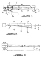
- a sootblower of the long retracting variety is shown as designated generally by reference character 10, the general construction of which is disclosed by U.S. Patent No. 2,668,978.
- Numerous additional features have been incorporated into sootblowers of the type shown subsequent to the above-mentioned disclosure (see, for example, U.S. Patent No. 3,439,376 .
- Such improvements are not involved in the present invention which is readily applicable to these and other sootblowers of the long retracting type.
- the sootblower depicted by Figure 1 will be recognized as typical of the structural and usage environment wherein the present invention can be advantageously employed.
- Lance tube 12 as shown in Figure 1 is inserted reciprocally into a boiler or furnace presumed to be located to the right in the illustration to clean the heat exchanging and other interior surfaces by the discharge of a blowing agent such as air and/or steam fran nozzles 14.
- Lance tube 12 is fixed to motor driven carriage 16 which controls the movement of the lance tube.
- Carriage 16 imparts a simultaneous rotational and longitudinal motion to lance tube 12 as it is cycled into and withdrawn fran the boiler to perform its cleaning function.
- Lance tube 12 is slidably overfitted upon stationary feed tube 18. Blowing medium supplied to feed tube 18 is controlled by blow valve 20 and is conducted into lance tube 12 and thereafter exits through nozzles 14.
- Carriage 16 includes drive motor 22.
- the illustrative sootblower blower considered herein has a single drive motor and employs a drive system having a fixed ratio between rate of translation and rotation.
- motor speed controller 28 could be connected to the translating motor or both the translating and rotating motors. It is also possible to control each of the motors with separate controllers.
- the lance tube is supported at all tines near the boiler wall outer surface by roller support 30, which is illustrated diagramatically.
- a principal aspect of the invention involves varying the driven speed of the lance as a function of the lance tube critical speed of rotation, which varies with lance projected length. Therefore, in order to practice this invention, it is necessary to determine the critical speed characteristics of the lance tube. It has been found that lance instability results primarily due to a rotational exitation. Several means of generating a critical rotation speed versus projected length curve may be utilized. An enpirical approach may be employed by extending a lance tube at various projected lengths and driving it rotatably until resonance is observed. Critical speed may also be calculated using a relationship known as Raleigh's method. The method is intended to calculate the critical speed of a rotating shaft having concentrated masses. Rayleigh's Method is expressed as: where
- Lance tube 12 is divided into a number of sections designated in the Figure as sections 1 through 3 which together encompass the entire lance tube projected length.
- the weights and deflections associated with the sections are measured and substituted into the Rayleigh's method equation above.
- the lance tube critical speed at full extension is nuch lower than at intermediate positions.
- the critical speed at full extension limits the rotational speed of a constant speed blower even though faster speeds would be allowable at travels . less than full lance tube extension.
- Figure 3 shows dimension "A” which is the variable lance tube overhung distance plotted along the abscissa in Figure 4.
- Dimension "B” in Figure 3 is the total lance tube length.
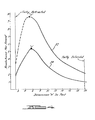
- the ordinate of the graph of Figure 4 is the rate of rotation of the lance tube in revolutions per second or Hertz.
- a graph is shown illustrating on the top curve 32, a limiting relationship between rotational lance speed in revolutions per second versus the lance overhung length and on bottom curve 34, a preferred safe operating curve.
- Curve 32 shows the critical speed of a typical twenty foot sootblower as determined by actual test.
- Curve 34 shown by Figure 4 is an exemplary lance tube speed operating curve selected as a result of the findings indicated by curve 32.
- the lance is driven at 50% of the critical speed of the lance.
- the 50% operating speed as oanpared to critical speed is desirable to insure that lance tube 12 does not develop a resonant condition.
- Outside excitation of the lance tube such as caused by slag striking the lance tube during operation or other force inputs may also cause the lance tube to resonate. at below the theoretical speed of resonance onset. Heating of the lance tube also causes a decrease in critical speed since the lance tube material modulus of elasticity changes in such environments. For these reasons, it is desirable to stay well below the actual critical speed of the lance.
- Speed variation of soot blower drive motor 22 may be accomplished by numerous means. For exanple, a continuously variable speed drive may be employed having a variable frequency power supply and an alternating current drive motor. Other types of controlling systems can be used with equal success.
- the speed control operating curve can be based on lance positions or time from the start of blower operation. Sensors along the length of the blower could also be used to determine lance position, which information may be employed to modulate the lance driving speed.
- this invention permits operating the lance at nuch higher rotational speeds during most of its travel than is possible with constant speed blowers. Higher rotational speeds permits increased translational speeds, thereby decreasing cycle time while maintaining a desired helix distance. Depending upon cleaning requirements, it may not be practical to increase the speed to the maximum indicated by intermediate portions of the curve 34. In these applications, it may be desirable to provide a constant speed of lance insertion or a constant speed of lance retraction and vary the other reciprocal motion in accordance with the teachings of this invention. For these applications, when adequate boiler cleaning is achieved during insertion or retraction, the total cycle time can be reduced by optimizing the other part of the cycle in accordance with the teachings of this invention.
- this invention permits a variation in the helix distance versus the projected length of the lance tube for sootblowers having independently oontrolleable rotation and translational movements.
- it may be desireable to increase the speed of lance rotation at intermediate projected distances while maintaining a nearly constant translaticnal speed, resulting in a shorter of "tighter" helix at the intermediate distances.
- Such shorter helix distance may be desireable in order to achieve desired clearing performance.
- the smallest needed helix distance will exist over the entire range of lance translational movement, resulting in a longer than necessary cycle tire. Cycle times become longer for shorter helix distance since resonance limits rotational speeds and translational speed is directly related to helix distance and rotational speed.
Landscapes
- Engineering & Computer Science (AREA)
- Combustion & Propulsion (AREA)
- Mechanical Engineering (AREA)
- General Engineering & Computer Science (AREA)
- Chemical & Material Sciences (AREA)
- Incineration Of Waste (AREA)
- Processing Of Solid Wastes (AREA)
- Preparation Of Compounds By Using Micro-Organisms (AREA)
- Polysaccharides And Polysaccharide Derivatives (AREA)
- Medicines Containing Plant Substances (AREA)
- Manufacture, Treatment Of Glass Fibers (AREA)
- Glass Compositions (AREA)
- Management, Administration, Business Operations System, And Electronic Commerce (AREA)
- Vehicle Body Suspensions (AREA)
- Treatment Of Sludge (AREA)
- Saccharide Compounds (AREA)
- Physical Or Chemical Processes And Apparatus (AREA)
Priority Applications (1)
| Application Number | Priority Date | Filing Date | Title |
|---|---|---|---|
| AT84306827T ATE31814T1 (de) | 1983-12-05 | 1984-10-05 | Russblaeservorrichtung in einem kessel und verfahren zu ihrem betrieb. |
Applications Claiming Priority (2)
| Application Number | Priority Date | Filing Date | Title |
|---|---|---|---|
| US06/558,380 US4492187A (en) | 1983-12-05 | 1983-12-05 | Sootblower apparatus |
| US558380 | 1983-12-05 |
Publications (3)
| Publication Number | Publication Date |
|---|---|
| EP0144131A2 true EP0144131A2 (de) | 1985-06-12 |
| EP0144131A3 EP0144131A3 (en) | 1985-11-21 |
| EP0144131B1 EP0144131B1 (de) | 1988-01-07 |
Family
ID=24229322
Family Applications (1)
| Application Number | Title | Priority Date | Filing Date |
|---|---|---|---|
| EP84306827A Expired EP0144131B1 (de) | 1983-12-05 | 1984-10-05 | Russbläservorrichtung in einem Kessel und Verfahren zu ihrem Betrieb |
Country Status (9)
| Country | Link |
|---|---|
| US (1) | US4492187A (de) |
| EP (1) | EP0144131B1 (de) |
| JP (1) | JPS60122813A (de) |
| AT (1) | ATE31814T1 (de) |
| AU (1) | AU559198B2 (de) |
| BR (1) | BR8404642A (de) |
| CA (1) | CA1240222A (de) |
| DE (1) | DE3468524D1 (de) |
| ZA (1) | ZA846315B (de) |
Cited By (2)
| Publication number | Priority date | Publication date | Assignee | Title |
|---|---|---|---|---|
| WO1993014887A1 (fr) * | 1992-01-23 | 1993-08-05 | Institut Teplofiziki Sibirskogo Otdelenia Akademii Nauk Sssr | Procede et dispositif d'elimination de depots de cendres des surfaces d'installations technologiques |
| EP0569161A3 (en) * | 1992-05-04 | 1993-12-22 | Babcock & Wilcox Co | Method and apparatus for constant progression of a cleaning jet across heated surfaces |
Families Citing this family (27)
| Publication number | Priority date | Publication date | Assignee | Title |
|---|---|---|---|---|
| EP0195994A3 (de) * | 1985-03-29 | 1987-02-04 | Siemens Aktiengesellschaft | Rohrgassen-Manipulator zum Hochdruckabschlämmmen von Wärmetauschern |
| US4583496A (en) * | 1985-04-19 | 1986-04-22 | Bergemann Gmbh | Soot blower |
| US4763696A (en) * | 1987-02-24 | 1988-08-16 | White Consolidated Industries, Inc. | Weld joint for soot blower lance tube |
| DE8712637U1 (de) * | 1987-09-18 | 1989-01-12 | Siemens AG, 1000 Berlin und 8000 München | Reinigungsgerät für Wärmetauscher mit Rohrbündeln, insbesondere für den Rohrboden- und Abstandshalterplattenbreich |
| JP2667429B2 (ja) * | 1988-02-26 | 1997-10-27 | バブコツク日立株式会社 | 長抜差形スートブロワおよびその運転方法 |
| US4915073A (en) * | 1988-05-25 | 1990-04-10 | Harth George H | Boiler tube wall inspection system |
| US5069172A (en) * | 1990-09-26 | 1991-12-03 | Westinghouse Electric Corp. | Nuclear steam generator sludge lance method and apparatus |
| US5416946A (en) * | 1992-05-01 | 1995-05-23 | The Babcock & Wilcox Company | Sootblower having variable discharge |
| US5355844A (en) * | 1993-05-26 | 1994-10-18 | Kendrick William E | System for slag removal and the like |
| CA2115109C (en) * | 1994-02-01 | 2000-04-25 | James P. Vanderberg | Automated sludge lance |
| US5505163B1 (en) * | 1994-03-18 | 1999-07-06 | Bergemann Usa Inc | Sootblower nozzle |
| US5619771A (en) * | 1995-08-11 | 1997-04-15 | Effox, Inc. | Oscillating and reverse cleaning sootblower |
| US6164956A (en) * | 1997-02-11 | 2000-12-26 | Ge Energy & Environmental Research Corporation | System and method for removing ash deposits in a combustion device |
| US5920951A (en) * | 1997-04-03 | 1999-07-13 | Diamond Power International, Inc. | Parameter sensing sootblower |
| RU2140618C1 (ru) * | 1998-01-08 | 1999-10-27 | Царев Дмитрий Эдуардович | Аппарат для очистки поверхности нагрева |
| US6772775B2 (en) * | 2000-12-22 | 2004-08-10 | Diamond Power International, Inc. | Sootblower mechanism providing varying lance rotational speed |
| US7055209B2 (en) * | 2003-04-04 | 2006-06-06 | Jss Power Solutions, Llc | Method and apparatus for converting a sootblower from a single motor to a dual motor drive |
| US7497224B2 (en) * | 2006-04-25 | 2009-03-03 | Randy Kahrig | Nozzle apparatus |
| US20080250597A1 (en) * | 2007-04-11 | 2008-10-16 | Holden Industries, Llc | Dual-motor sootblower |
| US8381690B2 (en) * | 2007-12-17 | 2013-02-26 | International Paper Company | Controlling cooling flow in a sootblower based on lance tube temperature |
| US7865996B1 (en) | 2009-12-18 | 2011-01-11 | Diamond Power International, Inc. | Sootblower with progressive cleaning arc |
| JP5795868B2 (ja) * | 2011-03-25 | 2015-10-14 | 住友重機械工業株式会社 | 付着灰除去装置の運用制御装置、及び、付着灰除去装置の運用の適正化方法 |
| US9541282B2 (en) | 2014-03-10 | 2017-01-10 | International Paper Company | Boiler system controlling fuel to a furnace based on temperature of a structure in a superheater section |
| US9927231B2 (en) * | 2014-07-25 | 2018-03-27 | Integrated Test & Measurement (ITM), LLC | System and methods for detecting, monitoring, and removing deposits on boiler heat exchanger surfaces using vibrational analysis |
| PL3172520T3 (pl) | 2014-07-25 | 2019-07-31 | International Paper Company | System i sposób określania lokalizacji zanieczyszczenia na powierzchni przenoszenia ciepła kotła |
| GB2586069B (en) * | 2019-08-01 | 2021-09-01 | Tube Tech International Ltd | Tube cleaning system and method |
| US20210341140A1 (en) | 2020-05-01 | 2021-11-04 | International Paper Company | System and methods for controlling operation of a recovery boiler to reduce fouling |
Family Cites Families (5)
| Publication number | Priority date | Publication date | Assignee | Title |
|---|---|---|---|---|
| FR1064610A (fr) * | 1949-06-07 | 1954-05-17 | Babcock & Wilcox Ltd | Perfectionnements aux dispositifs de ramonage pour chaudières |
| US3230568A (en) * | 1964-04-20 | 1966-01-25 | Diamond Power Speciality | Variable speed soot blower |
| US3782336A (en) * | 1971-10-21 | 1974-01-01 | Diamond Power Speciality | Method and apparatus for cleaning heated surfaces |
| US4437201A (en) * | 1981-11-13 | 1984-03-20 | White Consolidated Industries, Inc. | Soot blower |
| JPS58198616A (ja) * | 1982-05-17 | 1983-11-18 | Babcock Hitachi Kk | 長抜き差し型ス−トブロワの制御方法及びその装置 |
-
1983
- 1983-12-05 US US06/558,380 patent/US4492187A/en not_active Expired - Lifetime
-
1984
- 1984-08-14 ZA ZA846315A patent/ZA846315B/xx unknown
- 1984-08-15 CA CA000461096A patent/CA1240222A/en not_active Expired
- 1984-08-16 AU AU31968/84A patent/AU559198B2/en not_active Ceased
- 1984-09-10 JP JP59189481A patent/JPS60122813A/ja active Granted
- 1984-09-17 BR BR8404642A patent/BR8404642A/pt not_active IP Right Cessation
- 1984-10-05 EP EP84306827A patent/EP0144131B1/de not_active Expired
- 1984-10-05 DE DE8484306827T patent/DE3468524D1/de not_active Expired
- 1984-10-05 AT AT84306827T patent/ATE31814T1/de not_active IP Right Cessation
Cited By (2)
| Publication number | Priority date | Publication date | Assignee | Title |
|---|---|---|---|---|
| WO1993014887A1 (fr) * | 1992-01-23 | 1993-08-05 | Institut Teplofiziki Sibirskogo Otdelenia Akademii Nauk Sssr | Procede et dispositif d'elimination de depots de cendres des surfaces d'installations technologiques |
| EP0569161A3 (en) * | 1992-05-04 | 1993-12-22 | Babcock & Wilcox Co | Method and apparatus for constant progression of a cleaning jet across heated surfaces |
Also Published As
| Publication number | Publication date |
|---|---|
| CA1240222A (en) | 1988-08-09 |
| US4492187A (en) | 1985-01-08 |
| JPH0117053B2 (de) | 1989-03-28 |
| AU559198B2 (en) | 1987-02-26 |
| DE3468524D1 (en) | 1988-02-11 |
| EP0144131A3 (en) | 1985-11-21 |
| ZA846315B (en) | 1985-04-24 |
| AU3196884A (en) | 1985-06-13 |
| BR8404642A (pt) | 1985-08-06 |
| EP0144131B1 (de) | 1988-01-07 |
| JPS60122813A (ja) | 1985-07-01 |
| ATE31814T1 (de) | 1988-01-15 |
Similar Documents
| Publication | Publication Date | Title |
|---|---|---|
| US4492187A (en) | Sootblower apparatus | |
| CA2094468C (en) | Method and apparatus for constant progression of a cleaning jet across heated surfaces | |
| US6575122B2 (en) | Oscillating sootblower mechanism | |
| US5937954A (en) | Method for directional drilling | |
| US5555851A (en) | Automated sludge lance | |
| EP0568299A2 (de) | Russbläser mit Umleitung der Strömung in der Lanze | |
| JPS607199B2 (ja) | 回転式再生型熱交換器の伝熱板の清掃方法およびその装置 | |
| US6772775B2 (en) | Sootblower mechanism providing varying lance rotational speed | |
| US3230568A (en) | Variable speed soot blower | |
| EP0424487B1 (de) | Apparat zum bewegen eines flexiblen kabels durch ein zu reinigendes rohr | |
| JP3302234B2 (ja) | 高圧水デスケーリング装置 | |
| US5265671A (en) | Apparatus for mechanically projecting devices through tubes | |
| US4757785A (en) | Steam generator sludge removal apparatus | |
| US3375539A (en) | Traveling overhead textile machine cleaner | |
| US3593691A (en) | Wide jet soot blower | |
| US4893588A (en) | Adaptive control technique for steam generator cleaning | |
| AU683530B2 (en) | Process for the guiding of an elongated element | |
| US3216044A (en) | Long travel soot blower with contoured rail | |
| JP4801282B2 (ja) | 転炉羽口開口方法および装置 | |
| US1045742A (en) | Apparatus for removing scale and the like from boilers. | |
| US2221195A (en) | Flue cleaner | |
| BE902956A (nl) | Werkwijze en inrichting voor het reinigen van een pijpplaat van een verticale warmtewisselaar | |
| JPS58198616A (ja) | 長抜き差し型ス−トブロワの制御方法及びその装置 | |
| JPH10168713A (ja) | 織機における清掃装置 | |
| JPS6210575Y2 (de) |
Legal Events
| Date | Code | Title | Description |
|---|---|---|---|
| PUAI | Public reference made under article 153(3) epc to a published international application that has entered the european phase |
Free format text: ORIGINAL CODE: 0009012 |
|
| AK | Designated contracting states |
Designated state(s): AT BE CH DE FR GB IT LI LU NL SE |
|
| PUAL | Search report despatched |
Free format text: ORIGINAL CODE: 0009013 |
|
| AK | Designated contracting states |
Designated state(s): AT BE CH DE FR GB IT LI LU NL SE |
|
| 17P | Request for examination filed |
Effective date: 19851023 |
|
| 17Q | First examination report despatched |
Effective date: 19860314 |
|
| GRAA | (expected) grant |
Free format text: ORIGINAL CODE: 0009210 |
|
| AK | Designated contracting states |
Kind code of ref document: B1 Designated state(s): AT BE CH DE FR GB IT LI LU NL SE |
|
| REF | Corresponds to: |
Ref document number: 31814 Country of ref document: AT Date of ref document: 19880115 Kind code of ref document: T |
|
| ITF | It: translation for a ep patent filed | ||
| REF | Corresponds to: |
Ref document number: 3468524 Country of ref document: DE Date of ref document: 19880211 |
|
| ET | Fr: translation filed | ||
| PLBE | No opposition filed within time limit |
Free format text: ORIGINAL CODE: 0009261 |
|
| STAA | Information on the status of an ep patent application or granted ep patent |
Free format text: STATUS: NO OPPOSITION FILED WITHIN TIME LIMIT |
|
| 26N | No opposition filed | ||
| PGFP | Annual fee paid to national office [announced via postgrant information from national office to epo] |
Ref country code: FR Payment date: 19911021 Year of fee payment: 8 |
|
| PG25 | Lapsed in a contracting state [announced via postgrant information from national office to epo] |
Ref country code: LU Free format text: LAPSE BECAUSE OF NON-PAYMENT OF DUE FEES Effective date: 19921005 |
|
| ITTA | It: last paid annual fee | ||
| PGFP | Annual fee paid to national office [announced via postgrant information from national office to epo] |
Ref country code: LU Payment date: 19921231 Year of fee payment: 8 |
|
| EPTA | Lu: last paid annual fee | ||
| PG25 | Lapsed in a contracting state [announced via postgrant information from national office to epo] |
Ref country code: FR Effective date: 19930630 |
|
| REG | Reference to a national code |
Ref country code: FR Ref legal event code: ST |
|
| PGFP | Annual fee paid to national office [announced via postgrant information from national office to epo] |
Ref country code: DE Payment date: 19940916 Year of fee payment: 11 Ref country code: CH Payment date: 19940916 Year of fee payment: 11 |
|
| PGFP | Annual fee paid to national office [announced via postgrant information from national office to epo] |
Ref country code: SE Payment date: 19940920 Year of fee payment: 11 Ref country code: AT Payment date: 19940920 Year of fee payment: 11 |
|
| PGFP | Annual fee paid to national office [announced via postgrant information from national office to epo] |
Ref country code: GB Payment date: 19940927 Year of fee payment: 11 |
|
| PGFP | Annual fee paid to national office [announced via postgrant information from national office to epo] |
Ref country code: BE Payment date: 19940929 Year of fee payment: 11 |
|
| PGFP | Annual fee paid to national office [announced via postgrant information from national office to epo] |
Ref country code: NL Payment date: 19941031 Year of fee payment: 11 |
|
| EAL | Se: european patent in force in sweden |
Ref document number: 84306827.1 |
|
| PG25 | Lapsed in a contracting state [announced via postgrant information from national office to epo] |
Ref country code: AT Effective date: 19951005 Ref country code: GB Effective date: 19951005 |
|
| PG25 | Lapsed in a contracting state [announced via postgrant information from national office to epo] |
Ref country code: SE Effective date: 19951006 |
|
| PG25 | Lapsed in a contracting state [announced via postgrant information from national office to epo] |
Ref country code: BE Effective date: 19951031 Ref country code: LI Effective date: 19951031 Ref country code: CH Effective date: 19951031 |
|
| BERE | Be: lapsed |
Owner name: THE BABCOCK & WILCOX CY Effective date: 19951031 |
|
| PG25 | Lapsed in a contracting state [announced via postgrant information from national office to epo] |
Ref country code: NL Effective date: 19960501 |
|
| GBPC | Gb: european patent ceased through non-payment of renewal fee |
Effective date: 19951005 |
|
| REG | Reference to a national code |
Ref country code: CH Ref legal event code: PL |
|
| EUG | Se: european patent has lapsed |
Ref document number: 84306827.1 |
|
| NLV4 | Nl: lapsed or anulled due to non-payment of the annual fee |
Effective date: 19960501 |
|
| PG25 | Lapsed in a contracting state [announced via postgrant information from national office to epo] |
Ref country code: DE Effective date: 19960801 |
|
| PG25 | Lapsed in a contracting state [announced via postgrant information from national office to epo] |
Ref country code: LU Free format text: LAPSE BECAUSE OF NON-PAYMENT OF DUE FEES Effective date: 19911031 |