EP0144161A2 - Steuer- und Regelsystem für einen Wechselstrom-Motor - Google Patents
Steuer- und Regelsystem für einen Wechselstrom-Motor Download PDFInfo
- Publication number
- EP0144161A2 EP0144161A2 EP84307624A EP84307624A EP0144161A2 EP 0144161 A2 EP0144161 A2 EP 0144161A2 EP 84307624 A EP84307624 A EP 84307624A EP 84307624 A EP84307624 A EP 84307624A EP 0144161 A2 EP0144161 A2 EP 0144161A2
- Authority
- EP
- European Patent Office
- Prior art keywords
- angle
- current
- acceleration
- motor
- control
- Prior art date
- Legal status (The legal status is an assumption and is not a legal conclusion. Google has not performed a legal analysis and makes no representation as to the accuracy of the status listed.)
- Granted
Links
Images


Classifications
-
- H—ELECTRICITY
- H02—GENERATION; CONVERSION OR DISTRIBUTION OF ELECTRIC POWER
- H02P—CONTROL OR REGULATION OF ELECTRIC MOTORS, ELECTRIC GENERATORS OR DYNAMO-ELECTRIC CONVERTERS; CONTROLLING TRANSFORMERS, REACTORS OR CHOKE COILS
- H02P25/00—Arrangements or methods for the control of AC motors characterised by the kind of AC motor or by structural details
- H02P25/02—Arrangements or methods for the control of AC motors characterised by the kind of AC motor or by structural details characterised by the kind of motor
- H02P25/022—Synchronous motors
- H02P25/024—Synchronous motors controlled by supply frequency
Definitions
- This invention relates jenerally to a control system for an AC motor and more particularly to an AC motor control system having an inverter that supplies AC power to the AC motor.
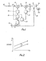
- FIG. 1 of the accompanying drawings shows an example of a conventional control system of an A C motor.
- reference numeral 10 designates a three-phase AC source, 11 a circuit breaker, 12 a thyristor converter, 13 a smoothing DC reactor, 14 a 120°-conduction inverter which includes thyristors, 15 an AC motor which is the load of the inverter 14, 151 a field winding of the AC motor, 152 a converter that supplies power to the field winding 151, 16 a desired speed setter, 24 a detector for detecting the speed of the AC motor, 17 a speed controller, 18 a current controller, 19 a phase controlled for controlling the output voltage of the converter 12, 20 a current detector, 23 a detector for detecting the overlap angle u of the inverter 14, 22 a voltage detector, and 21 a control lead angle ⁇ controller.
- AC power from the three-phase AC power source 10 is converted into a variable DC voltage by means of the converter 12, and is smoothed by the DC reactor 13. Thereafter, it is reversely converted into AC power by the inverter 14 and supplied to the AC motor 15.
- the converter 12 and the inverter 14 are controlled such that a speed reference signal, set by the speed setter 16, and a speed signal corresponding to the speed of the AC motor 15, as detected by the speed detector 24, are fed into the speed controller 17 where they are compared and amplified so as to produce a current reference signal.
- the thus produced current reference signal and the current signal detected by the current detector 20 are supplied to the current controller 18 where they are compared and amplified.
- the result of this comparison is fed into the phase controller 19 so as to control the output voltage of the converter 12.
- the overlap angle detector 23 detects the overlap angle u of the inverter 14 on the basis of currents at least detected by the current detector 20, voltages detected by the voltage detector 22 and frequencies detected by the speed detector 24.
- the thus detected overlap angle u and output voltage of the inverter 14 detected by the voltage detector 22 are fed into the controller 21, which, in turn, determines the firing pulse timing for respective thyristors of the inverter 14 so as to control the output frequency thereof.
- a control lead angle ⁇ is based on a y constant control which is given by the sum of a g asiant car dis ion marginal angl e ⁇ determined by the thyristors employed in the inverter 14 and an overlap angle u that increases in relation to an increase in current of the AC motor 15, and this relationship is shown in Figure 2.
- an ordant of this invention is to provide a novel control system for an alternating current motor, which is capable of controlled a control lead angle ⁇ without commutation failure even during periods of rapid mot.or acceleration or deceleration.
- a control system for an AC motor comprises a controllable thyristor converter for converting AC current from a power source to DC current, a thyristor inverter arranged to receive smoothed DC current from the converter and to convert it to AC current which is supplied to said AC motor; means for detecting the overlap angle of said inverter; and means for controlling the control lead angle of the inverter in response to said detected overlap angle; characterised in the provision of means for providing a signal representing a predetermined overlap angle, means for detecting the rate of acceleration-deceleration of the motor and wherein the control means controls the lead angle of the inverter in response to said signal representing said predetermined overlap angle when the acceleration-deceleration rate exceeds a predetermined value.
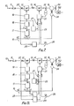
- FIG. 3 is a block diagram illustrating one embodiment of the invention.
- reference numeral 25 designates an acceleration-deceleration rate detector, 26 an overlap angle setter, and 27 a switch.
- the detector 25 operates the switch 27 to feed a specified overlap angle u set by the overlap angle setter 26 into the controller 21.
- reference numeral 28 designates a commutation marginal time controller that controls the commutation marginal time y .
- a signal indicative of the speed detected by the speed detected 24 is fed into the commutation marginal time controller 28 so as to be converted into an angle which, in turn, is summed with an overlap angleu detected by the overl ap angle detector 23 and fed into the controller 21.
- the switch 27 is operated to feed a signal representating a specified overlap angle u set by the overlap angle setter 26 into the controller 21 so as to control the control lead angle
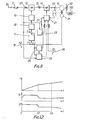
- Figure 6 is a diagram illustrating the relationship between speed, current and control lead angle ⁇ in the embodiment shown in Figure 5.
- the velocity increases and the acceleration-deceleration rate exceeds a specified acceleration-deceleration rate, so that a specified overlap angle is given and, thereafter, a control lead angle ⁇ is controlled on the basis of an overlap angle obtained by the overlap angle detector 23.
- the acceleration-deceleration rate of the motor is obtained by use of a speed signal, however, a current reference signal can also be used to obtain similar advantages.
- reference numeral 251 designates a current level detector that receives a signal indication of current and, when the current exceeds a specified value, it operates the switch 27 to feed a signal representing a specified overlap angle u set by the overlap angle setter 26 into the controller 21.
- the current When acceleration or deceleration is rapid, and the acceleration-deceleration exceeds a specified rate, the current also exceeds a specified level; this causes the switch 27 to be switched so as to feed a specified overlap angle to the control lead angle controller 21, whereby similar advantages can be obtained.
- the current level detector 251 functions to detect a current change rate in addition to comparing the current level, this enables the switch 27 to be switched to feed a specified overlap angle to the controller 21, so as to control the control lead angle ⁇ , even when an abrupt current change occurs, whereby a steady operation can also be obtained without any commutation failure.
- reference numeral 25 designates an acceleration-deceleration rate detector, 26 an overlap angle setter, and 27 a switch.
- the acceleration-deceleration rate detector 25 causes the switch 27 to be switched to feed a specified overlap angle u set by the overlap angle setter 26 into the control lead angle controller 21.
- the control lead angle ⁇ controller 21 also directly receives an output signal of the acceleration-deceleration rate detector 25.
- the control lead angl ⁇ controller 21 controls, on the basis of the output signal of the overlap angle detector 23 and the voltage detecting signal of the voltage detector 22, a control lead angle ⁇ in such a manner that commutation marginal time of the inverter 14 is maintained substantially constant independently of the speed of the AC motor 15.
- the control lead angle controller 21 controls, by use of an overlap angle u set by the overlap angle setter 26, a control lead angle ⁇ in such a manner that commutation marginal angle ⁇ of the inverter 14 is maintained substantially oonstant.
- the acceleration-deceleration rate detector 25 When the acceleration-deceleration rate is decreased, as caused by a decrease in the motor current, the acceleration-deceleration rate detector 25 causes the switch 27 to be reset on the basis of a current detecting signal applied by the current detector 20 as an input si gnal to another terminal of the acceleration-deceleration rate detector 25. Therefore, after the acceleration-deceleration rate has once exceeded a specified value, the acceleration-deceleration rate detector 25 maintains the above-described state until the current of the AC motor decreases to the specified value.
- Figure 10 is a diagram illustrating the relationship between current and control lead angle ⁇ .
- the control lead angle ⁇ controller 21 receives a specified overlap angle u set by the overlap angle setter 26 during the period from 0 to t2 in order to control a commutation marginal angle ⁇ so as to be substantially constant, so that, even when acceleration or deceleration is rapid, a necessary commutation marginal angle Y can be obtained, whereby steady operation of the AC motor can be secured without any commutation failure.
- the control lead angle ⁇ controller 21 controls the control lasd angle ⁇ such that the overlap angle u detected by the overlap angle detector 23 and the commutation marginal time ⁇ are maintained substantially constant, whereby the control lead angled becomes smaller and the operation power factor of the AC motor 15, which is expressed by the following equation: is enhanced.
- control lead angle ⁇ is determined as above described, the operation power factor is enhanced whereby the current of the AC motor is decreased and operation efficiency is also enhanced.
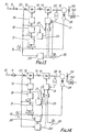
- Figures 11-14 show other embodiments according to the invention.
- the commutation marginal time controller 28 receives a speed signal and an output from the acceleration-deceleration rate detector 25, converts these signals into an angle and, in turn, feeds a signal corresponding to a commutation marginal angle ⁇ to the control lead angle ⁇ controller 21.
- the switch 27 Upon rapid acceleration or deceleration, if the acceleration-deceleration rate detector 25 detects that the acceleration-deceleration rate has exceeded a specified value, the switch 27 is caused to feed a specified overlap angle u set by the overlap setter 26 into the control lead angle ⁇ controller 21 so as to control the control lead angle ⁇ .
- the commutation rarginal time controller 28 controls the control lead angle controller 21 such that the commutation marginal angle is controlled to be substantially constant.
- the commutation marginal time contoller 28 controls the control lead angle ⁇ such that the commutation marginal time is controlled to be substantially constant.
- Figure 12 is a diagram illustrating the relationship between speed, current and the control lead angle ⁇ in the embodiment shown in Figure 11.
- the acceleration-deceleration rate is more than a specified value, so that a specified overlap angle u is fed into the control lead angle ⁇ controller 21 and, after the .time t2, an overlap angle obtained from the overlap angle detector 23 is fed to the control lead angle controller 21 so as to control a control lead angle
- a commutation marginal time is controlled such that a commutation marginal angle y is maintained constant until a time t3.
- the commutation marginal time is controlled so as to be substantially constant.
- the control lead angle becomes smaller compared to that existing in the period between the times t2 and t3.
- control of the AC motor 15 may be carried out only when the acceleration-deceleration rate detector 25 detects a specified acceleration rate or only when a specified deceleration rate is detected by the same. Namely, similar advantages can be obtained even when the control of the AC motor 15 is carried out separately in terms of when acceleration or deceleration is made.
- the acceleration-deceleration rate of speed is detected by use of a speed signal.
- a specified speed reference signal may also be used instead to achieve similar advantages.
- FIG. 13 and 14 show block diagrams illustrating other embodiments according to the invention.
- Reference numeral 251 designates the current level detector, which detects when the current exceeds a specified value, and then causes the switch 27 to be switched so as to feed a specified overlap angle u set by the overlap angle setter 26 into the control lead angle ⁇ controller 21.
- the current level detector 251 detects the current change rate.
- the current level detector 251 can cause the switch to be switched so as to feed a specified overlap angle u into the control lead angle ⁇ controller 21, whereby the control lead angle ⁇ is controlled. This achieves steady operation of the AC motor 15 without any commutation failure.
Landscapes
- Engineering & Computer Science (AREA)
- Power Engineering (AREA)
- Control Of Motors That Do Not Use Commutators (AREA)
Applications Claiming Priority (4)
| Application Number | Priority Date | Filing Date | Title |
|---|---|---|---|
| JP58206878A JPH0728543B2 (ja) | 1983-11-05 | 1983-11-05 | 交流電動機の制御装置 |
| JP206878/83 | 1983-11-05 | ||
| JP59088358A JPH0728544B2 (ja) | 1984-05-04 | 1984-05-04 | 交流電動機の制御装置 |
| JP88358/84 | 1984-05-04 |
Publications (3)
| Publication Number | Publication Date |
|---|---|
| EP0144161A2 true EP0144161A2 (de) | 1985-06-12 |
| EP0144161A3 EP0144161A3 (en) | 1988-07-06 |
| EP0144161B1 EP0144161B1 (de) | 1991-10-16 |
Family
ID=26429751
Family Applications (1)
| Application Number | Title | Priority Date | Filing Date |
|---|---|---|---|
| EP84307624A Expired - Lifetime EP0144161B1 (de) | 1983-11-05 | 1984-11-05 | Steuer- und Regelsystem für einen Wechselstrom-Motor |
Country Status (4)
| Country | Link |
|---|---|
| US (1) | US4633158A (de) |
| EP (1) | EP0144161B1 (de) |
| CA (1) | CA1252507A (de) |
| DE (1) | DE3485176D1 (de) |
Cited By (3)
| Publication number | Priority date | Publication date | Assignee | Title |
|---|---|---|---|---|
| EP0160310A3 (en) * | 1984-05-04 | 1986-11-05 | Kabushiki Kaisha Toshiba | Load-commutated inverter for operating synchronous motor |
| EP0227014A1 (de) * | 1985-12-24 | 1987-07-01 | Kabushiki Kaisha Toshiba | Hilfsantriebsgerät für eine Turbine |
| EP0597118A4 (de) * | 1992-06-01 | 1995-05-24 | Fanuc Ltd | Regelverfahren für einen synchronmotor. |
Families Citing this family (7)
| Publication number | Priority date | Publication date | Assignee | Title |
|---|---|---|---|---|
| GB8519270D0 (en) * | 1985-07-31 | 1985-09-04 | Gen Electric Co Plc | Induction motor drive arrangement |
| US5123080A (en) * | 1987-03-20 | 1992-06-16 | Ranco Incorporated Of Delaware | Compressor drive system |
| US5126642A (en) * | 1991-01-31 | 1992-06-30 | Ranco Incorporated Of Delaware | Variable speed motor control |
| DE19942493A1 (de) * | 1999-09-06 | 2001-03-08 | Wilo Gmbh | Verfahren zum Betrieb von Brushless DC-Motoren bei kleinen Drehzahlen |
| KR100786059B1 (ko) * | 2000-12-01 | 2007-12-17 | 엘지전자 주식회사 | 드럼세탁기의 탈수속도 제어방법 |
| JP2003200363A (ja) * | 2001-12-26 | 2003-07-15 | Makita Corp | バッテリ式電動工具 |
| JP5307855B2 (ja) * | 2011-06-30 | 2013-10-02 | 三菱電機株式会社 | 電動機制御装置、及びその電動機制御装置を用いた電動過給装置 |
Family Cites Families (5)
| Publication number | Priority date | Publication date | Assignee | Title |
|---|---|---|---|---|
| JPS5414281B2 (de) * | 1972-10-13 | 1979-06-06 | ||
| DD132826B1 (de) * | 1977-08-11 | 1980-03-19 | Frank Melzer | Einrichtung zur Beschleunigungsregelung von Elektromotoren |
| JPS5461616A (en) * | 1977-10-27 | 1979-05-18 | Toshiba Corp | Commutatorless motor |
| JPS5953795B2 (ja) * | 1978-02-03 | 1984-12-26 | 株式会社日立製作所 | サイリスタモ−タの制御装置 |
| DE3030465C2 (de) * | 1980-08-12 | 1982-06-03 | Siemens Ag, 1000 Berlin Und 8000 Muenchen | Verfahren zum Betrieb eines Umrichters mit Gleichstromzwischenkreis zur Speisung einer Drehfeldmaschine |
-
1984
- 1984-11-01 US US06/667,468 patent/US4633158A/en not_active Expired - Lifetime
- 1984-11-05 EP EP84307624A patent/EP0144161B1/de not_active Expired - Lifetime
- 1984-11-05 DE DE8484307624T patent/DE3485176D1/de not_active Expired - Lifetime
- 1984-11-05 CA CA000467060A patent/CA1252507A/en not_active Expired
Cited By (4)
| Publication number | Priority date | Publication date | Assignee | Title |
|---|---|---|---|---|
| EP0160310A3 (en) * | 1984-05-04 | 1986-11-05 | Kabushiki Kaisha Toshiba | Load-commutated inverter for operating synchronous motor |
| EP0227014A1 (de) * | 1985-12-24 | 1987-07-01 | Kabushiki Kaisha Toshiba | Hilfsantriebsgerät für eine Turbine |
| US4721861A (en) * | 1985-12-24 | 1988-01-26 | Kabushiki Kaisha Toshiba | Turbine helper drive apparatus |
| EP0597118A4 (de) * | 1992-06-01 | 1995-05-24 | Fanuc Ltd | Regelverfahren für einen synchronmotor. |
Also Published As
| Publication number | Publication date |
|---|---|
| DE3485176D1 (de) | 1991-11-21 |
| EP0144161B1 (de) | 1991-10-16 |
| EP0144161A3 (en) | 1988-07-06 |
| CA1252507A (en) | 1989-04-11 |
| US4633158A (en) | 1986-12-30 |
Similar Documents
| Publication | Publication Date | Title |
|---|---|---|
| US3983463A (en) | Method and apparatus for controlling the speed of induction motors | |
| EP0572729B1 (de) | Vorrichtung und Regelmethode zum Starten und Stoppen eines Dreiphasen-Induktionsmotors | |
| EP0013171A1 (de) | Regelgerät für einen Induktionsmotor | |
| EP0144161A2 (de) | Steuer- und Regelsystem für einen Wechselstrom-Motor | |
| US4758771A (en) | Apparatus for driving AC motor | |
| EP0053916A1 (de) | Steuersystem für einen Induktionsmotor unter Verwendung eines Umrichters als Wechselstromgenerator | |
| KR900007695B1 (ko) | 동기모터구동용 전력변환기의 제어방법과 그 장치 | |
| US4119897A (en) | Static convertor | |
| US4488100A (en) | Motor controller | |
| EP0160310A2 (de) | Lastkommutierter Wechselrichter zum Betrieb eines Synchronmotors | |
| US4058755A (en) | Kramer system utilizing a commutatorless motor | |
| US4314189A (en) | Device for controlling the commutating angle of an inverter device | |
| JPS60234487A (ja) | 交流電動機の制御装置 | |
| JPH0724475B2 (ja) | 同期電動機の制御方法 | |
| EP0446957B1 (de) | Prozedur zur Regelung der Sollgeschwindigkeit eines spannungsgeregelten Kurzschlussläufermotors | |
| JP2645159B2 (ja) | 誘導機の制御装置 | |
| JPH11197550A (ja) | 遠心分離機駆動用インダクションモータの出力制御装置 | |
| JPS6469281A (en) | Inverter controller | |
| JPH01231685A (ja) | 電圧形インバータ | |
| JPH0728543B2 (ja) | 交流電動機の制御装置 | |
| GB1575932A (en) | Method of and apparatus for control of multiphase motors | |
| JPH0158759B2 (de) | ||
| JPS6241598Y2 (de) | ||
| JP2693439B2 (ja) | 誘導電動機の制御装置 | |
| JPS60261384A (ja) | 交流電動機の制御装置 |
Legal Events
| Date | Code | Title | Description |
|---|---|---|---|
| PUAI | Public reference made under article 153(3) epc to a published international application that has entered the european phase |
Free format text: ORIGINAL CODE: 0009012 |
|
| 17P | Request for examination filed |
Effective date: 19841116 |
|
| AK | Designated contracting states |
Designated state(s): DE FR GB SE |
|
| PUAL | Search report despatched |
Free format text: ORIGINAL CODE: 0009013 |
|
| AK | Designated contracting states |
Kind code of ref document: A3 Designated state(s): DE FR GB SE |
|
| 17Q | First examination report despatched |
Effective date: 19900117 |
|
| GRAA | (expected) grant |
Free format text: ORIGINAL CODE: 0009210 |
|
| AK | Designated contracting states |
Kind code of ref document: B1 Designated state(s): DE FR GB SE |
|
| ET | Fr: translation filed | ||
| REF | Corresponds to: |
Ref document number: 3485176 Country of ref document: DE Date of ref document: 19911121 |
|
| PLBE | No opposition filed within time limit |
Free format text: ORIGINAL CODE: 0009261 |
|
| STAA | Information on the status of an ep patent application or granted ep patent |
Free format text: STATUS: NO OPPOSITION FILED WITHIN TIME LIMIT |
|
| 26N | No opposition filed | ||
| EAL | Se: european patent in force in sweden |
Ref document number: 84307624.1 |
|
| PGFP | Annual fee paid to national office [announced via postgrant information from national office to epo] |
Ref country code: GB Payment date: 19961028 Year of fee payment: 13 |
|
| PG25 | Lapsed in a contracting state [announced via postgrant information from national office to epo] |
Ref country code: GB Free format text: LAPSE BECAUSE OF NON-PAYMENT OF DUE FEES Effective date: 19971105 |
|
| GBPC | Gb: european patent ceased through non-payment of renewal fee |
Effective date: 19971105 |
|
| REG | Reference to a national code |
Ref country code: FR Ref legal event code: D6 |
|
| PGFP | Annual fee paid to national office [announced via postgrant information from national office to epo] |
Ref country code: SE Payment date: 20031105 Year of fee payment: 20 |
|
| PGFP | Annual fee paid to national office [announced via postgrant information from national office to epo] |
Ref country code: FR Payment date: 20031110 Year of fee payment: 20 |
|
| PGFP | Annual fee paid to national office [announced via postgrant information from national office to epo] |
Ref country code: DE Payment date: 20031113 Year of fee payment: 20 |
|
| EUG | Se: european patent has lapsed | ||
| REG | Reference to a national code |
Ref country code: FR Ref legal event code: TP |