EP0144168A2 - Aus Keramik oder Porzellan hergestellter Warmhaltebehälter, sowie Verfahren zu dessen Herstellung - Google Patents
Aus Keramik oder Porzellan hergestellter Warmhaltebehälter, sowie Verfahren zu dessen Herstellung Download PDFInfo
- Publication number
- EP0144168A2 EP0144168A2 EP84307688A EP84307688A EP0144168A2 EP 0144168 A2 EP0144168 A2 EP 0144168A2 EP 84307688 A EP84307688 A EP 84307688A EP 84307688 A EP84307688 A EP 84307688A EP 0144168 A2 EP0144168 A2 EP 0144168A2
- Authority
- EP
- European Patent Office
- Prior art keywords
- vessel
- enamel
- hollow chamber
- above mentioned
- reduced pressure
- Prior art date
- Legal status (The legal status is an assumption and is not a legal conclusion. Google has not performed a legal analysis and makes no representation as to the accuracy of the status listed.)
- Withdrawn
Links
- 239000000919 ceramic Substances 0.000 title claims abstract description 64
- 238000000034 method Methods 0.000 title claims description 32
- 229910052573 porcelain Inorganic materials 0.000 title claims description 27
- 210000003298 dental enamel Anatomy 0.000 claims abstract description 97
- 238000002844 melting Methods 0.000 claims description 17
- 230000008018 melting Effects 0.000 claims description 17
- 239000005995 Aluminium silicate Substances 0.000 claims description 16
- 235000012211 aluminium silicate Nutrition 0.000 claims description 16
- NLYAJNPCOHFWQQ-UHFFFAOYSA-N kaolin Chemical compound O.O.O=[Al]O[Si](=O)O[Si](=O)O[Al]=O NLYAJNPCOHFWQQ-UHFFFAOYSA-N 0.000 claims description 16
- 239000004927 clay Substances 0.000 claims description 9
- 230000008602 contraction Effects 0.000 claims description 8
- 238000010438 heat treatment Methods 0.000 claims description 7
- 238000001816 cooling Methods 0.000 claims description 6
- 238000010422 painting Methods 0.000 claims description 4
- 238000007599 discharging Methods 0.000 claims description 2
- 239000002320 enamel (paints) Substances 0.000 claims description 2
- 239000000155 melt Substances 0.000 claims description 2
- 238000007789 sealing Methods 0.000 claims description 2
- 230000000694 effects Effects 0.000 description 9
- 238000010304 firing Methods 0.000 description 7
- 230000002093 peripheral effect Effects 0.000 description 7
- 239000007767 bonding agent Substances 0.000 description 5
- XLYOFNOQVPJJNP-UHFFFAOYSA-N water Substances O XLYOFNOQVPJJNP-UHFFFAOYSA-N 0.000 description 5
- VYPSYNLAJGMNEJ-UHFFFAOYSA-N Silicium dioxide Chemical compound O=[Si]=O VYPSYNLAJGMNEJ-UHFFFAOYSA-N 0.000 description 4
- 238000005034 decoration Methods 0.000 description 4
- 235000013305 food Nutrition 0.000 description 4
- 241001122767 Theaceae Species 0.000 description 3
- 239000004744 fabric Substances 0.000 description 3
- 238000007796 conventional method Methods 0.000 description 2
- 238000002474 experimental method Methods 0.000 description 2
- 239000000835 fiber Substances 0.000 description 2
- 239000000377 silicon dioxide Substances 0.000 description 2
- 239000010425 asbestos Substances 0.000 description 1
- 235000013405 beer Nutrition 0.000 description 1
- 239000011230 binding agent Substances 0.000 description 1
- 230000015572 biosynthetic process Effects 0.000 description 1
- 239000003822 epoxy resin Substances 0.000 description 1
- 239000010433 feldspar Substances 0.000 description 1
- 239000003365 glass fiber Substances 0.000 description 1
- 239000011796 hollow space material Substances 0.000 description 1
- 238000004519 manufacturing process Methods 0.000 description 1
- 239000002184 metal Substances 0.000 description 1
- 238000000465 moulding Methods 0.000 description 1
- 239000003973 paint Substances 0.000 description 1
- 239000005011 phenolic resin Substances 0.000 description 1
- 229920000647 polyepoxide Polymers 0.000 description 1
- 229910052895 riebeckite Inorganic materials 0.000 description 1
- 239000000454 talc Substances 0.000 description 1
- 229910052623 talc Inorganic materials 0.000 description 1
- 230000007306 turnover Effects 0.000 description 1
Images


Classifications
-
- B—PERFORMING OPERATIONS; TRANSPORTING
- B28—WORKING CEMENT, CLAY, OR STONE
- B28B—SHAPING CLAY OR OTHER CERAMIC COMPOSITIONS; SHAPING SLAG; SHAPING MIXTURES CONTAINING CEMENTITIOUS MATERIAL, e.g. PLASTER
- B28B1/00—Producing shaped prefabricated articles from the material
- B28B1/002—Producing shaped prefabricated articles from the material assembled from preformed elements
-
- A—HUMAN NECESSITIES
- A47—FURNITURE; DOMESTIC ARTICLES OR APPLIANCES; COFFEE MILLS; SPICE MILLS; SUCTION CLEANERS IN GENERAL
- A47G—HOUSEHOLD OR TABLE EQUIPMENT
- A47G19/00—Table service
- A47G19/02—Plates, dishes or the like
- A47G19/027—Plates, dishes or the like with means for keeping food cool or hot
-
- A—HUMAN NECESSITIES
- A47—FURNITURE; DOMESTIC ARTICLES OR APPLIANCES; COFFEE MILLS; SPICE MILLS; SUCTION CLEANERS IN GENERAL
- A47G—HOUSEHOLD OR TABLE EQUIPMENT
- A47G19/00—Table service
- A47G19/12—Vessels or pots for table use
- A47G19/127—Vessels or pots for table use with means for keeping liquid cool or hot
-
- A—HUMAN NECESSITIES
- A47—FURNITURE; DOMESTIC ARTICLES OR APPLIANCES; COFFEE MILLS; SPICE MILLS; SUCTION CLEANERS IN GENERAL
- A47G—HOUSEHOLD OR TABLE EQUIPMENT
- A47G19/00—Table service
- A47G19/22—Drinking vessels or saucers used for table service
- A47G19/2288—Drinking vessels or saucers used for table service with means for keeping liquid cool or hot
-
- A—HUMAN NECESSITIES
- A47—FURNITURE; DOMESTIC ARTICLES OR APPLIANCES; COFFEE MILLS; SPICE MILLS; SUCTION CLEANERS IN GENERAL
- A47J—KITCHEN EQUIPMENT; COFFEE MILLS; SPICE MILLS; APPARATUS FOR MAKING BEVERAGES
- A47J41/00—Thermally-insulated vessels, e.g. flasks, jugs, jars
- A47J41/02—Vacuum-jacket vessels, e.g. vacuum bottles
- A47J41/022—Constructional details of the elements forming vacuum space
- A47J41/024—Constructional details of the elements forming vacuum space made of glass
-
- B—PERFORMING OPERATIONS; TRANSPORTING
- B28—WORKING CEMENT, CLAY, OR STONE
- B28B—SHAPING CLAY OR OTHER CERAMIC COMPOSITIONS; SHAPING SLAG; SHAPING MIXTURES CONTAINING CEMENTITIOUS MATERIAL, e.g. PLASTER
- B28B11/00—Apparatus or processes for treating or working the shaped or preshaped articles
- B28B11/04—Apparatus or processes for treating or working the shaped or preshaped articles for coating or applying engobing layers
- B28B11/044—Apparatus or processes for treating or working the shaped or preshaped articles for coating or applying engobing layers with glaze or engobe or enamel or varnish
Definitions
- This invention relates to a warmth keeping vessel made of ceramics or porcelain and a method of producing the same.
- Vessels made of ceramics or porcelain are utilized mostly, for example, as tableware. In order to serve as tableware, it is not sufficient for them to be vessels for merely containing things. That is to-say, the vessels are required to maintain the temperature of foods within them to prolong the tasting time of the foods, in other words, to be able to keep warm things warm for a fixed time and to keep cold things cold for a fixed time.
- ceramic or porcelaneous products are' so comparatively low in the warmth keeping effect that a conventional method taken to bring a warmth keeping effect is to increase the thickness of a ceramic or porcelaneous vessel itself, to preheat the vessel with hot water or the like or to keep the vessel cool in advance in a refrigerator or the like.
- this has been still insufficient to prolong the above described tasting time.
- it is thought to make a ceramic or porcelaneous vessel of a sealed double-walled structure as in a thermos bottle.
- the ceramic or porcelaneous product is made by heating and firing kaolin above 1000 degrees. Therefore, even if an airtight hollow chamber is formed of double walls by molding kaolin in a vessel mold, when it is simply baked, air within the hollow chamber will expand due to heating and the warmth keeping ceramic or porcelaneous vessel itself will break. Thus, it has been difficult to seal a hollow chamber with heating and firing.
- the present invention is made in view of such circumstances as are described above and has as an object to provide a double-walled vessel made of ceramics or porcelain and having a warmth keeping effect and a method of producing the same.
- a particular object of the present invention is to provide a double-walled vessel wherein air in a hollow space between double walls made of ceramics or porcelain is discharged together with firing and then said space is sealed with an enamel so as to be an adiabatic part to be able to control the conduction of heat as much as possible and a method of producing the same.
- a more particular object of the present invention is to provide a ceramic or porcelaneous vessel not only effective to keep warmth but also valuable enough as an article.
- the problem to be solved by the present invention is to provide a warmth keeping vessel made of ceramics or porcelain, simple to manufacture, higher in the airtightness of the reduced pressure airtight chamber and adapted to apply a three-dimensional decoration and a method of producing the same.
- the drawings show warmth keeping ceramic or porcelaneous vessels embodying the present invention.
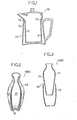
- Fig. 1 shows a vertically sectioned view of a pot 10 embodying the present invention.
- This pot 10 is made of ceramics or porcelain and, needless to say, is painted with an enamel 15 on the surface. Further, this pot 10 is formed by bonding on the joint 13 an inner vessel 11 and outer vessel 12 as separated from each other to form a sealed airtight chamber R under a reduced pressure between the inner vessel 11 and outer vessel 12 so as to be a ceramic or porcelaneous vessel of a double-walled structure having a sealed airtight chamber under a reduced pressure.
- the first producing method of the present invention is a method wherein an inner vessel 11 and outer vessel 12 forming a warmth keeping ceramic or porcelaneous vessel of a double-walled structure are formed of kaolin, are respectively simply baked, are overlapped on each other so as to form a hollow chamber, are then painted with an enamel 15 on the joint 13 of them, are heated at a temperature rather lower than the melting point of the enamel 15 to discharge air in the hollow chamber and are further fired at a temperature higher than the melting point of said enamel 15 so as to be bonded together to keep the hollow chamber airtight under a reduced pressure.
- the simply baked inner vessel 11 and outer vessel 12 are overlapped on each other to form a hollow chamber, are heated at a temperature lower than the melting point of the enamel 15 to expand air in the hollow chamber and discharge it through the joint 13 of the inner vessel 11 and outer vessel 12 and are then fired at a temperature higher than the melting point of the enamel 15 to bond the joint 13 with the molten enamel.
- This first producing method shall be explained more in detail with reference to the porcelaneous bottle 10a shown in Figs. 2 and-3.
- This - bottle-shaped vessel 10a is formed of an inner vessel 11 and an outer vessel 12.
- the inner vessel 11 is substantially bottle-shaped and is of a maximum diameter in the shoulder part.
- the outer vessel 12 is of the shape of a bottle 10a with the part above the shoulder cut off and has a barrel thicker than the above mentioned inner vessel 11.
- the shoulder part of the inner vessel 11 will contact the upper peripheral edge of the outer.vessel 12 and the - inner vessel 11 will not be able to enter the outer vessel 12 any more.
- a hollow chamber is formed of the outer peripheral wall of the inner vessel 11 and the inner peripheral wall of the outer vessel 12.
- the hollow chamber is formed of the outer peripheral wall of the inner vessel 11 and the inner peripheral wall of the outer vessel 12 and the inner vessel 11 and outer vessel 12 contact with each other on the opening edge of this hollow chamber and are sealed.
- the inner vessel 11 may exactly fit in the outer vessel 12.
- Such inner vessel 11 and outer vessel 12 are respectively formed of ordinary kaolin for porcelain and are simply baked by a normal method, are then, as required, printed with pictures and are painted with an enamel 15.
- This enamel 15 is an ordinary enamel of 50% feldspar, 25% silica, 15% kaolin and 10% talc.
- the outer vessel 12 and the inner vessel 11 as contained in the outer vessel 12 are fired at a temperature (of about 1000°C.) rather lower than the melting point (of about 1200°) of the enamel 15 for about 2 hours. As they are fired at a temperature (of about 1000°C.) lower than the melting point (of about 1200°C.) of the enamel 15, the enamel 15 will not be melted and the expanded air within the hollow chamber will be discharged through the above mentioned joint 13.
- the inner and outer vessels are further heated and are fired at a temperature (of 1300°C. of an ordinary firing temperature) higher than the melting point of the enamel for 2 hours to be finished. Then, the enamel 15 will melt to bond the joint 13 of the inner vessel 11 and outer vessel 12 and seal the - hollow chamber.
- the hollow chamber is kept airtight 'under a reduced pressure by the enamel 15 bonding the joint 13 of the inner vessel 11 and outer vessel 12. ;
- the melting point of the enamel 15 is about 1200°C.
- the melting point of the enamel 15 will be lower and therefore the firing temperature will be also lower.
- the vessel itself will be mostly low in the airtightness and the inner vessel 11 and outer vessel 12 may be painted all over with the enamel to utilize the airtightness of the enamel 15 to increase the airtightness of the vessel itself.
- an inner vessel 11 and outer vessel 12 are formed of kaolin, the inner vessel 11 in a kaolin stste is put into the outer vessel 12 in a kaolin state and both are jointed airtightly with each other on a joint 13 positioned in the upper end part.
- the joint 13 of the thus made inner vessel 11 and outer vessel 12 is smoothed with a sponge or cloth so as to be smooth and one or more fine holes 14 are made in a part of the outer vessel.
- the joint 13 of the inner vessel 11 and outer vessel 12 is smoothed with a sponge or cloth so as not to be visible in the appearance when the coffee cut 10b is completed as a product.
- the optimum diameter of the fine hole 14 is about 0.5 mm. according to the experiments made by the Inventors. The number of such fine holes depends on the size of the vessel itself made of ceramics or porcelain but one hole is sufficient for the size -of the coffee cup 10b.
- the coffee cup 10b in this state is simply baked to be well dried. This baking temperature is 700 to 800°C. After this simple baking, the coffee cup 10b is painted all over with an enamel 15. (The state in Fig. 7.)
- the neamel is the same ordi- . nary one as in the first producing method.
- this coffee cup 10b is heated for 8 to 9,minutes at such high temperature (of about 500 to 700 0 C.) as will not melt the enamel 15 on the surface to utilize the . thermal expansion of the air within the airtight chamber R under a reduced pressure to discharge the air.
- this coffee cup 10b is heated for 3 to 4 minutes at such temperature (of about 1200 to 1300°C.) as will.melt the enamel 15.
- the detailed phenomenon is not known, at this time, too, air remaining within the airtight chamber R under a reduced pressure will further expand to be discharged through the respective fine holes 14.
- this coffee cup 10b is cooled gradually over at least 7 to 8 minutes so as to suck the enamel 15 molten at the beginning of this cooling into the airtight chamber R under a reduced pressure through the respective fine holes 14 with the pressure difference by the contraction of the air within the airtight chamber R under a reduced pressure.
- the enamel 15 will close the respective fine holes 14 and a part of the enamel 15 will cover also the outer vessel 12 positioned near the insides of the respective fine holes 14.
- the hollow chamber will be kept airtight under a reduced pressure by the enamel 15 filling the respective fine holes 14 communicating with the hollow chamber and flowing into the hollow chamber so as to be solidified.
- a tea pot 10c or dish 10d is also a ceramic or porcelaneous vessel having such formation as is mentioned above.
- the respective fine holes 14 as formed in the outer vessel 12 have been explained.
- the respective fine holes 14 may be formed in the inner vessel 11. Further, if the respective fine holes 14 are provided not only in the bottom of the vessel as in the above mentioned embodiment but also, for example, in the lower part of a handle 16 of the tea pot 10c shown in Fig. 9, the fine holes 14 will be harder to see.
- an opening 11b may be formed in a vessel 11a in which a space Ra to be an airtight chamber R under a reduced pressure is formed in advance and a lid 11c may be jointed with this opening 11b and may be solidified to form a vessel.
- a hollow chamber provided in a ceramic or porcelaneous product can be easily made airtight under a reduced pressure, the thermal conduction of the contents in the inner vessel 11 is comparatively slow and the preserving effect is remarkably high. That is to say, in case the temperature of the contents in the vessel is higher than the ambient temperature, the heat will be lost substantially only from the surface of the contents. This fact is very different from the fact that, in the conventional vessel, heat has been discharged and exchanged on all of the surface of the contents and the outer periphery of the vessel. Needless to say, even in case the temperature of the contents in the vessel is lower than the ambient temperature, heat will be exchanged comparatively more slowly then in the conventional vessel.
- the fine holes 14 are provided in the part in which the enamel 15-is likely to accumulate, the excess enamel 15a will be sucked into the airtight chamber R under a reduced pressure, therefore the parts in which the enamel 15 accumulates on the outer surface of the ceramic or porcelaneous vessel will be able to be eliminated and, when the ceramic or porcelaneous vessel is completed as an article, such fine holes 14 will not appear on the surface and therefore the value as of an article will not be reduced.
- the respective fine holes 14 may be only formed in advance in the inner vessel 11 or outer vessel 12 and a double-walled vessel high in the warmth keeping effect will be able to be very simply and positively produced.
- the present invention is to provide a warmth keeping vessel having both of the advantage of ceramics or porcelain and a warmth keeping property by utilizing the conventional apparatus for producing ceramics and porcelain and is very high in the utility value particularly as of tableware vessels.
- Fig. 15 shows a vertically sectioned view of a warmth keeping ceramic or porcelaneous vessel 20 (which is in fact a beer jar-or cup) according to the present invention.
- a reduced pressure airtight chamber R is formed by an outer vessel 21 and inner vessel 22 and not only the outside surface of the warmth keeping ceramic or porcelaneous vessel 20 but also the inside surfaces of both outer vessel 21 and inner vessel 22 are coated with an enamel 23.
- a hole 24 is formed in a part of the outer vessel forming this warmth keeping ceramic or porcelaneous vessel 20 and an inserted part 25a of a plug 25 is inserted in this hole 24.
- this plug 25 is coated with the enamel 23 but also the clearances between this plug 25 and outer vessel 21 and between the inserted part 25a of the plug 25 and hole 24 are impregnated and embedded with the solidified enamel 23. Further, such one-point mark (such decoration as a symbol or trademark) as is shown in Fig. 19 is applied to the surface of the head part 25b of the plug 25.
- the outer vessel 21, inner vessel 22 and plug 25 are formed of kaolin, the inner vessel 22 in a clay state is put into the outer vessel 21 also in a clay state and both are jointed with each other in a joint located in the upper end part so as to form an airtight chamber Ra to be one reduced pressure airtight chamber R.
- One or more holes are made in a proper part of the outer vessel 21 in the clay state. It is proper that the diameter of this hole 24 is about 5 to 15 mm. (See Fig. 17).
- the outer vessel 21, inner vessel 22 and plug 25 in such state are simply baked.
- the temperature of this baking is different with the kaolin to be used but is about 700 to 800°C.
- the size' (diameter) of the inserted part 25a of the plug 25 while in the clay state is so determined as to be able to form such clearance as will allow air to come in and go out between them when the inserted part 25a of the plug 25 is inserted into the hole 24 of the simply baked outer vessel 21 as described later.
- the clearance of the above described condition will be able to be well formed by the contraction of both by the simple baking. (See Figs. 19 to 21).
- the enamel 23 is poured through the hole 24 -into the airtight chamber Ra formed by the simply baked outer vessel 21 and inner vessel 22 to paint the entire inner surfaces of the outer vessel 21 and inner vessel 22 forming the airtight chamber Ra with the enamel 23.
- the hole 24 is comparatively large, even if the hole 24 is one, it will be easy to pour in the enamel and discharge the residue.
- such operations will be able to be made more efficiently.
- the inserted part 25a of the plug 25 is inserted into the hole 24 of the outer vessel 21 and is fixed with a bonding agent 26.
- the bonding agent 26 to be used here may be such as will not eliminate the bond between the inserted part 25a and hole 24 at least until the temperature at which the enamel 23 melts.
- the bonding agent satisfying such condition is considered to be a phenol resin or epoxy resin as a binder reinforced with asbestos, glass fibers, silica fibers or metal fibers. However, simply even a kaolin as dissolved in water will be good enough.
- this bonding agent 26 it should be noted that it is not applied to the entire outer periphery of the inserted part 25a of the plug 25 but is applied partly, because a clearance will be required between the hole 24 and inserted part 25a so that inflated air within the airtight chamber Ra will be able to be discharged out in the case of the later described firing.
- the bonding agent 26 may be applied in the form of about two or three lines in the axial direction of the inserted part 25a. Then, the surfaces of the outer vessel 21, inner vessel 22 and plug 25 are painted with the enamel 23.
- the above operation may be carried out in such manner that the simply baked outer vessel 21 and inner vessel 22 are dipped in the enamel 23 contained in a tank, then the excess enamel within the airtight chamber Ra is discharged through the hole 24 and then the plug 25 painted with the enamel 23 -on the head part 25b' is fixed in the inserted part 25a to the hole 24.
- the outer vessel 21, inner vessel 22 and plug 25 thus made integral and painted with the enamel 23 are heated for 8 to 9 minutes at such high temperature (of 500 to 700°C.) that the enamel 23 on the surfaces will not melt and the air within the airtight chamber Ra will be discharged out by the thermal expansion.
- a plurality-of such projections as are shown in Fig. 21 may be provided on the inner surface of the head part 25b of the plug 25 so as to positively form a clearance between the head part 25b and outer vessel 21.
- the surface of the outer vessel 21 will be curved and therefore, even if such projections 25c as are mentioned above are not provided on the head part 25b, there will be a clearance large enough to discharge air. Further, as shown in Fig. 20, the head part 25b of the plug 25 may be partly embedded in a part of the outer vessel 21.
- these outer vessel 21, inner vessel 22 and plug 23 are heated or fired for 3 to 4 minutes at such high temperature (of 1200 to 1300°C.) that the enamel 23 will completely melt..
- these outer vessel 21, inner vessel 22 and plug 25 are cooled in turn over at least 7 to 8 minutes so that the enamel 23 molten in the initial period of this cooling will be sucked into the airtight chamber Ra through the clearance between the hole 24 and plug 25 by the pressure difference by the contraction of the air within the airtight chamber Ra.
- the'enamel 23 will completely close the clearance between the hole 24 and plug 25 and will solidify. Therefore, the airtight chamber Ra will be closed after most of the air within it is discharged and therefore, in case the warmth keeping ceramic or porcelaneous vessel 20 is placed under the normal temperature, the airtight chamber Ra will be a reduced pressure airtight chamber R literally sealed under a reduced pressure.
- the thermal conduction of the contents within the inner vessel 22 will be comparatively slow. That is to say, in case the temperature of the contents within the inner vessel 22 is higher than the ambient temperature, the heat will be very slowly lost only from the surface of the contents and the joint of the outer vessel 21 and inner vessel 22. Needless to say, in case the temperature of the contents within the inner vessel 22 is lower than the ambient temperature, the outside heat will be comparatively slowly conducted into the inner vessel 22 and the temperature of the contents will rise slowly.
- the enamel 23 will completely melt and then cool and therefore will be so to say automatically sucked to the reduced pressure airtight chamber R side by the pressure difference between inside and outside the reduced pressure airtight chamber R so as to completely seal the clearance between the hole 24 and plug 25.
- the plug 25 will be positively secured to the outside surface of the outer vessel by this enamel 23.
- the excess enamel 23 will be sucked to the reduced pressure airtight chamber R side by the pressure difference in the reduced pressure airtight chamber R and will enter the clearance between the outer vessel 21 and plug 25 due to the surface tension before it solidifies and therefore will not accumulate on the surface of the outer vessel.
- a proper decoration may be applied to the surface of the head part 25b of the above described plug 25.
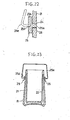
- the decoration may be, for example, a trademark, one-point mark or symbol mark of the manufacturer of this warmth keeping ceramic or porcelaneous vessel 20. Further, if such work as, for example, a hole 25d as shown in Fig. 22 or projection is formed on the head part 25b of this plug 25, it will be able to be made a handle 25e fitting part as shown in Fig. 23.
- the reduced pressure airtight chamber R is formed by the outer vessel 21 and inner vessel 22 and both inside and outside surfaces of them are coated with the enamel 23, even if fine cracks have been produced in the outer vessel 21 or inner vessel 22, they will be doubly covered with the enamel 23 and therefore will not impair the airtightness within the reduced pressure airtight chamber.
- the plug 25 is used in forming the reduced pressure airtight chamber R, a one-point mark or the like can be utilized as attached to this plug 25 and the value as of a product can be further elivated. Needless to say, if this plug 25 - is made a part to fit the handle 25e for carrying the vessel, the handle 25e will be able to be fitted and removed more simply than ever.
- the reduced pressure airtightness of the reduced pressure airtight chamber can be made more positive and the warmth keeping ceramic or porcelaneous vessels having decorative parts indicating one-point marks or the like three-dimensionally can be produced simultaneously and easily.
Landscapes
- Engineering & Computer Science (AREA)
- Food Science & Technology (AREA)
- Chemical & Material Sciences (AREA)
- Ceramic Engineering (AREA)
- Mechanical Engineering (AREA)
- Physics & Mathematics (AREA)
- Thermal Sciences (AREA)
- Manufacturing & Machinery (AREA)
- Structural Engineering (AREA)
- Cookers (AREA)
- Table Devices Or Equipment (AREA)
- Ceramic Products (AREA)
Applications Claiming Priority (6)
| Application Number | Priority Date | Filing Date | Title |
|---|---|---|---|
| JP21928083A JPS60111614A (ja) | 1983-11-21 | 1983-11-21 | 陶磁器製保温容器及びその製造方法 |
| JP219280/83 | 1983-11-21 | ||
| JP141095/84 | 1984-07-07 | ||
| JP14109584A JPS6121958A (ja) | 1984-07-07 | 1984-07-07 | 陶磁器製保温容器及びその製造方法 |
| JP205418/84 | 1984-09-29 | ||
| JP20541884A JPS6182719A (ja) | 1984-09-29 | 1984-09-29 | 陶磁器製保温容器及びその製造方法 |
Publications (2)
| Publication Number | Publication Date |
|---|---|
| EP0144168A2 true EP0144168A2 (de) | 1985-06-12 |
| EP0144168A3 EP0144168A3 (de) | 1986-03-19 |
Family
ID=27318183
Family Applications (1)
| Application Number | Title | Priority Date | Filing Date |
|---|---|---|---|
| EP84307688A Withdrawn EP0144168A3 (de) | 1983-11-21 | 1984-11-07 | Aus Keramik oder Porzellan hergestellter Warmhaltebehälter, sowie Verfahren zu dessen Herstellung |
Country Status (1)
| Country | Link |
|---|---|
| EP (1) | EP0144168A3 (de) |
Cited By (6)
| Publication number | Priority date | Publication date | Assignee | Title |
|---|---|---|---|---|
| WO1986004541A1 (en) * | 1985-02-11 | 1986-08-14 | Kirsten Kampp | A double- or multi-walled thermos container of a ceramic material, and a method and a mould for producing it |
| FR2718156A1 (fr) * | 1994-03-30 | 1995-10-06 | Mireur Georges | Vaisselle chauffante à préhensions froides. |
| GB2418834A (en) * | 2004-10-11 | 2006-04-12 | Donna Compton | Drinking vessel |
| FR2907705A1 (fr) * | 2006-10-25 | 2008-05-02 | Elmeceram Sa | Procede et dispositif de fabrication d'un recipient en ceramique |
| CN110526741A (zh) * | 2019-09-06 | 2019-12-03 | 醴陵市观前瓷业有限公司 | 一种陶瓷色釉喷涂工艺 |
| CN111588244A (zh) * | 2020-06-28 | 2020-08-28 | 云南自然空间门窗有限公司 | 一种双层陶瓷结构保温碗及其制作方法 |
Family Cites Families (4)
| Publication number | Priority date | Publication date | Assignee | Title |
|---|---|---|---|---|
| DE259863C (de) * | ||||
| DE222753C (de) * | ||||
| DE402741C (de) * | 1918-06-01 | 1924-09-17 | Mantle Lamp Company | Verfahren zur Herstellung einer Verbindung zwischen zwei Teilen eines Gegenstandes mittels Lackes und Hitzebehandlung |
| GB952800A (en) * | 1961-02-06 | 1964-03-18 | George Lester Wax | Insulated container and method of making same |
-
1984
- 1984-11-07 EP EP84307688A patent/EP0144168A3/de not_active Withdrawn
Cited By (6)
| Publication number | Priority date | Publication date | Assignee | Title |
|---|---|---|---|---|
| WO1986004541A1 (en) * | 1985-02-11 | 1986-08-14 | Kirsten Kampp | A double- or multi-walled thermos container of a ceramic material, and a method and a mould for producing it |
| FR2718156A1 (fr) * | 1994-03-30 | 1995-10-06 | Mireur Georges | Vaisselle chauffante à préhensions froides. |
| GB2418834A (en) * | 2004-10-11 | 2006-04-12 | Donna Compton | Drinking vessel |
| FR2907705A1 (fr) * | 2006-10-25 | 2008-05-02 | Elmeceram Sa | Procede et dispositif de fabrication d'un recipient en ceramique |
| CN110526741A (zh) * | 2019-09-06 | 2019-12-03 | 醴陵市观前瓷业有限公司 | 一种陶瓷色釉喷涂工艺 |
| CN111588244A (zh) * | 2020-06-28 | 2020-08-28 | 云南自然空间门窗有限公司 | 一种双层陶瓷结构保温碗及其制作方法 |
Also Published As
| Publication number | Publication date |
|---|---|
| EP0144168A3 (de) | 1986-03-19 |
Similar Documents
| Publication | Publication Date | Title |
|---|---|---|
| US4595437A (en) | Method of producing a warmth keeping vessel made of ceramics or porcelain | |
| CN104936491A (zh) | 具有在高温下固化的内涂层的双壁、真空绝缘容器 | |
| CN107962905B (zh) | 一种玻璃嵌制品及其制备方法 | |
| EP0144168A2 (de) | Aus Keramik oder Porzellan hergestellter Warmhaltebehälter, sowie Verfahren zu dessen Herstellung | |
| CN113766993A (zh) | 制造容器的方法和相关系统 | |
| CN106734941A (zh) | 一种能更改熔模精密铸造中芯头自由端稳定性的方法 | |
| CN101222851B (zh) | 用于制造食品的工艺和由此制造的食品 | |
| KR100734439B1 (ko) | 장식 패턴을 갖는 와인 병 및 그 제조 방법 | |
| EP3577089A1 (de) | Verfahren zur herstellung eines natürlich kühlenden keramikbehälters | |
| JPS6182719A (ja) | 陶磁器製保温容器及びその製造方法 | |
| JPH0535707B2 (de) | ||
| EP0781256B1 (de) | Verfahren und vorrichtung zum herstellen von gegenständen aus glas order kristall | |
| JPS6121958A (ja) | 陶磁器製保温容器及びその製造方法 | |
| WO2006005002A2 (en) | Insulated vessel | |
| JPS61191583A (ja) | 陶磁器製2重構造容器の空気流出孔密閉方法 | |
| KR100446915B1 (ko) | 전기로를 이용한 유리공예품 제조방법 | |
| US1165951A (en) | Method of providing enameled vessels with sealed passageways. | |
| CN116040920B (zh) | 双色双只玻璃花瓶的一体成型制作工艺 | |
| JPH0482084B2 (de) | ||
| EP0211909A1 (de) | Ein isolierter behälter mit zwei oder mehr wänden aus keramischem material und verfahren und form zu seiner herstellung | |
| JPS63242983A (ja) | 断熱機能を有する焼物容器の製造方法 | |
| JPH10316481A (ja) | 二重構造の焼物容器の内外容器接着・空気流出孔密閉方法 | |
| US20210348853A1 (en) | Method for producing crockery filled with phase-change material | |
| KR20050011332A (ko) | 방울이 구비된 도자 물품의 제조방법 | |
| JPS60111614A (ja) | 陶磁器製保温容器及びその製造方法 |
Legal Events
| Date | Code | Title | Description |
|---|---|---|---|
| PUAI | Public reference made under article 153(3) epc to a published international application that has entered the european phase |
Free format text: ORIGINAL CODE: 0009012 |
|
| AK | Designated contracting states |
Designated state(s): AT BE CH DE FR GB IT LI LU NL SE |
|
| PUAL | Search report despatched |
Free format text: ORIGINAL CODE: 0009013 |
|
| AK | Designated contracting states |
Kind code of ref document: A3 Designated state(s): AT BE CH DE FR GB IT LI LU NL SE |
|
| STAA | Information on the status of an ep patent application or granted ep patent |
Free format text: STATUS: THE APPLICATION IS DEEMED TO BE WITHDRAWN |
|
| 18D | Application deemed to be withdrawn |
Effective date: 19861120 |
|
| RIN1 | Information on inventor provided before grant (corrected) |
Inventor name: YAMAMOTO, MASASHIGE |