EP0144191A2 - Verfahren zur Untersuchung von unterirdischen Röhrenleitungen - Google Patents
Verfahren zur Untersuchung von unterirdischen Röhrenleitungen Download PDFInfo
- Publication number
- EP0144191A2 EP0144191A2 EP84308019A EP84308019A EP0144191A2 EP 0144191 A2 EP0144191 A2 EP 0144191A2 EP 84308019 A EP84308019 A EP 84308019A EP 84308019 A EP84308019 A EP 84308019A EP 0144191 A2 EP0144191 A2 EP 0144191A2
- Authority
- EP
- European Patent Office
- Prior art keywords
- pipeline
- ionising radiation
- intensity
- test vehicle
- cover
- Prior art date
- Legal status (The legal status is an assumption and is not a legal conclusion. Google has not performed a legal analysis and makes no representation as to the accuracy of the status listed.)
- Granted
Links
- 238000007689 inspection Methods 0.000 title claims description 5
- 230000005855 radiation Effects 0.000 claims abstract description 39
- 238000000034 method Methods 0.000 claims abstract description 20
- 230000003993 interaction Effects 0.000 claims abstract description 4
- 230000001678 irradiating effect Effects 0.000 claims abstract description 3
- 230000002285 radioactive effect Effects 0.000 claims abstract description 3
- 238000012360 testing method Methods 0.000 claims description 50
- 238000001228 spectrum Methods 0.000 claims description 23
- 230000004907 flux Effects 0.000 claims description 10
- 239000011248 coating agent Substances 0.000 claims description 9
- 238000000576 coating method Methods 0.000 claims description 9
- 238000005259 measurement Methods 0.000 claims description 6
- 238000012545 processing Methods 0.000 claims description 5
- 238000006243 chemical reaction Methods 0.000 claims description 4
- 230000003213 activating effect Effects 0.000 claims description 2
- 238000004458 analytical method Methods 0.000 claims description 2
- 239000000203 mixture Substances 0.000 claims description 2
- 230000000063 preceeding effect Effects 0.000 claims 5
- UAGDSHSRQZJWSQ-HYJBFAGTSA-N Radiatin Chemical compound O[C@@H]1[C@@H](C)[C@@H]2C=CC(=O)[C@@]2(C)[C@@H](OC(=O)C(C)=C)[C@@H]2[C@H](C)C(=O)O[C@@H]21 UAGDSHSRQZJWSQ-HYJBFAGTSA-N 0.000 claims 1
- UAGDSHSRQZJWSQ-UHFFFAOYSA-N Radiatin Natural products OC1C(C)C2C=CC(=O)C2(C)C(OC(=O)C(C)=C)C2C(C)C(=O)OC21 UAGDSHSRQZJWSQ-UHFFFAOYSA-N 0.000 claims 1
- JUFPAXGQNKVGNT-UHFFFAOYSA-N dihydrocliviasine Natural products CN1CCC2CC(O)C3OC(O)c4cc5OCOc5cc4C3C12 JUFPAXGQNKVGNT-UHFFFAOYSA-N 0.000 claims 1
- 239000000463 material Substances 0.000 description 7
- UFHFLCQGNIYNRP-UHFFFAOYSA-N Hydrogen Chemical compound [H][H] UFHFLCQGNIYNRP-UHFFFAOYSA-N 0.000 description 5
- 230000008859 change Effects 0.000 description 5
- 229910052739 hydrogen Inorganic materials 0.000 description 5
- 239000001257 hydrogen Substances 0.000 description 5
- 238000010586 diagram Methods 0.000 description 4
- 239000012530 fluid Substances 0.000 description 4
- 238000003860 storage Methods 0.000 description 4
- XLYOFNOQVPJJNP-UHFFFAOYSA-N water Substances O XLYOFNOQVPJJNP-UHFFFAOYSA-N 0.000 description 4
- 239000010426 asphalt Substances 0.000 description 3
- HGLDOAKPQXAFKI-OUBTZVSYSA-N californium-252 Chemical compound [252Cf] HGLDOAKPQXAFKI-OUBTZVSYSA-N 0.000 description 3
- 230000000694 effects Effects 0.000 description 3
- 239000003550 marker Substances 0.000 description 3
- 239000003381 stabilizer Substances 0.000 description 3
- XEEYBQQBJWHFJM-UHFFFAOYSA-N Iron Chemical compound [Fe] XEEYBQQBJWHFJM-UHFFFAOYSA-N 0.000 description 2
- 238000012935 Averaging Methods 0.000 description 1
- ZOXJGFHDIHLPTG-UHFFFAOYSA-N Boron Chemical compound [B] ZOXJGFHDIHLPTG-UHFFFAOYSA-N 0.000 description 1
- 229910000831 Steel Inorganic materials 0.000 description 1
- 238000000862 absorption spectrum Methods 0.000 description 1
- 230000009471 action Effects 0.000 description 1
- 230000002238 attenuated effect Effects 0.000 description 1
- 229910052796 boron Inorganic materials 0.000 description 1
- 238000009933 burial Methods 0.000 description 1
- 238000004364 calculation method Methods 0.000 description 1
- 239000003795 chemical substances by application Substances 0.000 description 1
- 238000004140 cleaning Methods 0.000 description 1
- 230000007797 corrosion Effects 0.000 description 1
- 238000005260 corrosion Methods 0.000 description 1
- 230000007423 decrease Effects 0.000 description 1
- 230000007547 defect Effects 0.000 description 1
- 238000001514 detection method Methods 0.000 description 1
- 230000003628 erosive effect Effects 0.000 description 1
- 239000002657 fibrous material Substances 0.000 description 1
- 239000003365 glass fiber Substances 0.000 description 1
- 229910001385 heavy metal Inorganic materials 0.000 description 1
- 229910052742 iron Inorganic materials 0.000 description 1
- 238000004519 manufacturing process Methods 0.000 description 1
- 230000000149 penetrating effect Effects 0.000 description 1
- 239000004033 plastic Substances 0.000 description 1
- 229920003023 plastic Polymers 0.000 description 1
- 230000008569 process Effects 0.000 description 1
- 239000012857 radioactive material Substances 0.000 description 1
- 230000000246 remedial effect Effects 0.000 description 1
- 230000008439 repair process Effects 0.000 description 1
- 239000013535 sea water Substances 0.000 description 1
- 230000035945 sensitivity Effects 0.000 description 1
- 239000007787 solid Substances 0.000 description 1
- 230000006641 stabilisation Effects 0.000 description 1
- 239000010959 steel Substances 0.000 description 1
- 238000005728 strengthening Methods 0.000 description 1
- 238000010998 test method Methods 0.000 description 1
- 238000009827 uniform distribution Methods 0.000 description 1
Images



Classifications
-
- G—PHYSICS
- G01—MEASURING; TESTING
- G01N—INVESTIGATING OR ANALYSING MATERIALS BY DETERMINING THEIR CHEMICAL OR PHYSICAL PROPERTIES
- G01N23/00—Investigating or analysing materials by the use of wave or particle radiation, e.g. X-rays or neutrons, not covered by groups G01N3/00 – G01N17/00, G01N21/00 or G01N22/00
- G01N23/22—Investigating or analysing materials by the use of wave or particle radiation, e.g. X-rays or neutrons, not covered by groups G01N3/00 – G01N17/00, G01N21/00 or G01N22/00 by measuring secondary emission from the material
- G01N23/221—Investigating or analysing materials by the use of wave or particle radiation, e.g. X-rays or neutrons, not covered by groups G01N3/00 – G01N17/00, G01N21/00 or G01N22/00 by measuring secondary emission from the material by activation analysis
- G01N23/222—Investigating or analysing materials by the use of wave or particle radiation, e.g. X-rays or neutrons, not covered by groups G01N3/00 – G01N17/00, G01N21/00 or G01N22/00 by measuring secondary emission from the material by activation analysis using neutron activation analysis [NAA]
-
- G—PHYSICS
- G01—MEASURING; TESTING
- G01M—TESTING STATIC OR DYNAMIC BALANCE OF MACHINES OR STRUCTURES; TESTING OF STRUCTURES OR APPARATUS, NOT OTHERWISE PROVIDED FOR
- G01M3/00—Investigating fluid-tightness of structures
- G01M3/005—Investigating fluid-tightness of structures using pigs or moles
-
- G—PHYSICS
- G01—MEASURING; TESTING
- G01N—INVESTIGATING OR ANALYSING MATERIALS BY DETERMINING THEIR CHEMICAL OR PHYSICAL PROPERTIES
- G01N2223/00—Investigating materials by wave or particle radiation
- G01N2223/07—Investigating materials by wave or particle radiation secondary emission
- G01N2223/074—Investigating materials by wave or particle radiation secondary emission activation analysis
-
- G—PHYSICS
- G01—MEASURING; TESTING
- G01N—INVESTIGATING OR ANALYSING MATERIALS BY DETERMINING THEIR CHEMICAL OR PHYSICAL PROPERTIES
- G01N2223/00—Investigating materials by wave or particle radiation
- G01N2223/07—Investigating materials by wave or particle radiation secondary emission
- G01N2223/074—Investigating materials by wave or particle radiation secondary emission activation analysis
- G01N2223/0745—Investigating materials by wave or particle radiation secondary emission activation analysis neutron-gamma activation analysis
-
- G—PHYSICS
- G01—MEASURING; TESTING
- G01N—INVESTIGATING OR ANALYSING MATERIALS BY DETERMINING THEIR CHEMICAL OR PHYSICAL PROPERTIES
- G01N2223/00—Investigating materials by wave or particle radiation
- G01N2223/20—Sources of radiation
- G01N2223/202—Sources of radiation isotopes
-
- G—PHYSICS
- G01—MEASURING; TESTING
- G01N—INVESTIGATING OR ANALYSING MATERIALS BY DETERMINING THEIR CHEMICAL OR PHYSICAL PROPERTIES
- G01N2223/00—Investigating materials by wave or particle radiation
- G01N2223/30—Accessories, mechanical or electrical features
- G01N2223/302—Accessories, mechanical or electrical features comparative arrangements
-
- G—PHYSICS
- G01—MEASURING; TESTING
- G01N—INVESTIGATING OR ANALYSING MATERIALS BY DETERMINING THEIR CHEMICAL OR PHYSICAL PROPERTIES
- G01N2223/00—Investigating materials by wave or particle radiation
- G01N2223/30—Accessories, mechanical or electrical features
- G01N2223/308—Accessories, mechanical or electrical features support of radiation source
-
- G—PHYSICS
- G01—MEASURING; TESTING
- G01N—INVESTIGATING OR ANALYSING MATERIALS BY DETERMINING THEIR CHEMICAL OR PHYSICAL PROPERTIES
- G01N2223/00—Investigating materials by wave or particle radiation
- G01N2223/60—Specific applications or type of materials
- G01N2223/61—Specific applications or type of materials thin films, coatings
-
- G—PHYSICS
- G01—MEASURING; TESTING
- G01N—INVESTIGATING OR ANALYSING MATERIALS BY DETERMINING THEIR CHEMICAL OR PHYSICAL PROPERTIES
- G01N2223/00—Investigating materials by wave or particle radiation
- G01N2223/60—Specific applications or type of materials
- G01N2223/628—Specific applications or type of materials tubes, pipes
-
- G—PHYSICS
- G01—MEASURING; TESTING
- G01N—INVESTIGATING OR ANALYSING MATERIALS BY DETERMINING THEIR CHEMICAL OR PHYSICAL PROPERTIES
- G01N2223/00—Investigating materials by wave or particle radiation
- G01N2223/60—Specific applications or type of materials
- G01N2223/634—Specific applications or type of materials wear behaviour, roughness
Definitions
- the present invention relates to the inspection of buried pipelines to determine the integrity or nature of the cover of such pipelines.
- a method of testing the integrity of the cover of buried pipelines is disclosed in the specification of UK Patent No. 1,563,540 in which the intensity of nuclear ionising radiations arising from nuclear reactions occurring naturally in the material surrounding the pipeline and penetrating the wall of the pipeline is measured by an instrumented vehicle which travels through the pipeline.
- the measured y-ray intensity spectrum is compared with one taken on a previous occasion and any differences are detected and noted.
- a number of detectors are disposed symmetrically about the axis of the vehicle, and their outputs are compared with one another. Any large difference indicates a similar difference in the pipeline cover.
- a method of determining the nature of the cover of a buried pipeline wherein there is included the operations of irradiating the inner wall of the pipeline with neutrons from a radioactive source carried by a vehicle traversing the pipeline, measuring the intensity of ionising radiation within the pipeline arising from nuclear interactions occuring within the cover of the pipeline and its surroundings due to the neutrons emitted by the source, and recording the data representative of the measured intensity of the said ionising radiation together with data representative of the position of the vehicle along the pipeline.
- a test vehicle for the determination of the nature of the cover of a buried pipeline, wherein there is included a chassis adapted to be moved along a pipeline the nature of the cover of which is to be determined, the chassis carrying a neutron source so positioned as to irradiate the inner surface of the wall of the pipeline with a constant flux of neutrons, means for measuring the intensity of ionising radiation within the pipeline arising from nuclear interactions occurring within the cover of the pipeline and its surroundings due to the neutrons emitted by the neutron source, means for determining the position of the test vehicle along the pipeline and means for recording data related to the intensity of the said ionising radiation within the pipeline, together with data representative of the position of the test vehicle along the pipeline.
- the intensity of ionising radiation having energy greater than a specified threshold energy is measured either at a position at a known axial distance from the source, or simultaneously at two positions at different axial distances from the neutron source, and the rate of change of the neutron flux density with distance from the source along the pipeline is determined from the ratio of the two measurements of the intensity of the ionising radiation.
- one or more portions of the energy spectrum of the ionising radiation within the pipeline may be measured.
- Any change in the axial gradient of the neutron flux is indicative of a loss of pipeline cover because as water has a greater hydrogen density than does either the concrete and/or other medium in which the pipeline is buried, there will be an increase in the moderation of energy of neutrons in the water surrounding the pipeline, and hence a change in the intensity of the resulting ionising radiation within the pipeline.
- the concrete coating which in normal conditions surrounds the buried pipeline attenuates both outgoing and incoming radiations.
- the presence or absence of the concrete coating is indicated by changes in the intensity of Y- rays within the pipeline due to neutron capture by hydrogen in the medium outside the pipeline. In the absence of the concrete, this is increased due to the increase in the hydrogen content of the medium immediately surrounding the pipeline.
- the intensity of high-energy Y-rays generated by the capture of neutrons in the concrete coating and the iron pipe wall pipeline is higher when the concrete coating is present and decreases in its absence, again due to increased neutron capture in the hydrogenous medium outside the pipeline.
- the data, which is recorded may be either Y-ray spectra, or neutron, absorption spectra, and can be taken regularly over fixed increments of distance along the pipeline, or of time, or by another markercriterion, for example every pipeline section, or submultiple of this, as indicated by the detection of joints in the pipeline.
- the spectra may be stored in their entirety, or selected parts only may be stored, or they may be processed prior to storage, for example ratios between corresponding parts of successive spectra may be determined, and stored.
- Data may be selected for storage either continuously for given regions of the pipeline, or when a departure from a norm occurs.
- the norm may be determined either by means of the temporary storage and averaging of data from one or more previous sections of pipeline, or the norm may be preset before the test vehicle is launched into the pipeline.
- the chassis of the test vehicle may be adapted to carry two detectors for the said ionising radiation positioned at different axial distances from the neutron source, or a single detector at a predetermined axial distance from the neutron source.
- the or each detector comprise a plurality of individual detectors disposed symmetrically so as to observe the inner surface of the wall of the pipeline radially so as to provide information as to the azimuth of the measured ionising radiation.
- the means for recording the measured intensities of the ionising radiation may be adapted to carry out the determination of the rate of fall-off of the neutron flux with axial distance from the neutron source and record this parameter.
- the said means may be further adapted to record the said parameter only when it departs from a predetermined value known to be indicative of a satisfactorily coated and buried pipeline, together with appropriate position data when such a departure from the specified value of the parameter occurs.
- the method comprises the operations of continuously determining the spectrum of Y-rays within the pipeline arising from the said nuclear reactions, temporarily storing the Y-ray spectrum determined at a given instant, comparing the stored Y-ray spectrum with one determined at a later instant, the stored Y- ray spectrum being continuously up-dated, and recording differences between the Y- ray spectra above a predetermined level together with data representative of the position of the vehicle along the pipeline at which the recorded differences in the Y-ray spectra within the pipeline occur.
- the chassis of the test vehicle includes means for determining the spectra of Y-radiation within the pipeline arising from the said nuclear reactions, means for temporarily storing the Y-ray spectra determined at a given instant, means for continuously up-dating the Y-ray spectra stored in the temporary store, means for comparing the stored Y- ray spectrum with one determined at a later instant, means for determining the position of the vehicle along the pipeline, a data recorder for recording Y- ray spectra and position data, and means for activating the data recorder whenever the difference between a temporarily stored Y- ray spectrum and a later determined Y- ray spectrum exceeds a predetermined value.
- the energy spectrum of the ionising radiation is measured, together with position data, and stored for analysis later. Again, this may be done at one or two axial locations.
- the ionising radiation may be Y- rays or thermal neutrons returning from the media surrounding the pipeline.
- a suitable neutron source is a quantity of Californium -252
- suitable Y-ray detectors are NaI (Tl) scintillation detectors.
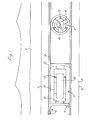
- the first test vehicle designed by the reference numeral 1
- the second test vehicle is based on an inflated rubber sphere.
- the test vehicle is designed to be transmitted through the pipeline by the fluid which is flowing through it.
- test vehicles 1 and 2 are shown within a length of steel pipeline 3 which is clad with a layer of bitumen 4, which can include some fibrous material such as felt or woven glass fibre as a strengthening agent.
- the pipeline 3 is laid in a trench 5 in the sea bed 6.
- the pipeline 3 is embedded in concrete 7 prior to back-filling of the trench 5.
- the test vehicle 1 consists of a cylindrical chassis 10 which is supported between two pistons, 11 and 12 which are of a fit within the pipeline 3 such that the test vehicle 1 can be propelled along the pipeline 3 by a fluid 8 flowing through the pipeline 3.
- At the leading end of the chassis 10 of the test vehicle 1 are six separate Californium-252 neutron sources 13.
- the neutron sources 13 are arranged to irradiate evenly the wall 14 of the pipeline 3.
- the neutron sources 13 are mounted within, and shielded by, the structure of the chassis 10 of the test vehicle l. Behind the neutron sources 13 are six NaI (Tl) scintillation Y-ray detectors 15.
- the scintillation Y- ray detectors 15 are spaced regularly around the chassis 10 of the test vehicle 1 so that they together observe the whole of the inner surface of the wall 14 of the pipeline 3.
- the output signals from the scintillation Y-ray detectors 15 are fed into a battery-powered electronics and recording module 16 to which signals representative of the position of the test vehicles along the length of the pipeline also are applied.
- the position signals can be derived either from clock pulses, on the assumption that the test vehicle 1 passes through the pipeline 3 at a constant speed, or by counting the number of joints between sections of the pipeline 3 which have been passed by the vehicle 1. These joints can be detected by the distorting effect they have on the Y-ray spectra determined by the Y- ray detectors 15. Alternatively, a mechanical or time based position data signal generator can be used.
- Each of the Y- ray detectors 15 has its own identified input channel to the module 16 so that the azimuths of the Y-rays 15 can be determined.
- the six separate neutron sources can be replaced by a single source on the centre-line of the vehicle and arranged to irradiate the wall 14 of the pipeline 3 via an aperture or apertures shielding surrounding the central source.
- the second type of test vehicle shown in Figure 1 is based on an inflated rubber sphere 17 which again is propelled along the pipeline 3 by the fluid flowing through it.
- Those components of the spherical test vehicle 2 which correspond to those of the cylindrical test vehicle 1 and have the same purpose, have the same reference numerals.
- the main difference is in the number of source/detector pairs.
- six are used disposed in a single plane at right angles to the longitudinal axis of the test vehicle 1.
- the source/detector pairs are disposed in three dimensions so as to observe the whole solid angle of 271.
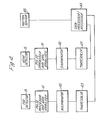
- FIG. 2 there is shown a single channel of the data processing and recording system within the electronics and recording module 16.
- Signals representative of Y-rays falling on one of the Y-ray detectors 15 are amplified by a pre-amplifier 20 and passed to an analogue-to-digital converter 21.
- the output Y- ray data signals from the analogue-to-digital converter 21 are passed to a short term store, or memory, 22 and directly to a memory interrogator 24. After a delay of some seconds the stored Y-ray data signals are released to the memory interrogator 24 via a memory buffer 25 and replaced by fresh signals from the analogue-to-digital converter 21. This up-dating is carried on continuously.
- the direct and stored Y-ray signals are compared in the memory interrogator 24. If they are broadly comparable, then there is no output from the memory interrogator 24. If the two sets of Y-ray data signals differ by more than a predetermined amount, then the memory interrogator 24 produces an output signal which is applied to a data processor 25 which reduces it to a form which is suitable to be recorded on a high density tape rcorder 26.
- the data processor 25 also produces a control signal which actuates a controller 27.
- the controller 27 operates so as to switch on the tape recorder 26 only when there is an output from the date processor 25, and also causes position marking signals from a distance marker 28 to be applied to the tape recorder 26.
- all the circuit components from the analogue to digital converter 21 onwards are multi-channel, there being a channel for each Y -ray detector 15.
- the detectors each have a pre-amplifier 20.
- the electronics and recording module 16 is powered by battery 29 and a high voltage generator 30.
- the distance marker 28 counts the number of pipeline joints which have been passed by the test vehicle from the position at which it was introduced into the pipeline.
- the joints can be detected mechanically, or by their effect on the Y-ray spectrum within the pipeline at the positions at which they occur.
- the position of a marked change in the cover of pipeline can be determined to within one length of pipeline.
- the position marking signals can be derived from clock pulses counted by the distance marker 28.
- the test vehicle 1 of which only a portion is shown carries a ring of separate Californium - 252 neutron sources 13 arranged so as to irradiate evenly the inner surface of the wall 14 of the pipeline 3.
- Behind the neutron sources 13 are two groups of NaI (Tl)scintillation Y-ray detectors 15.
- the Y-ray detectors 15 in each group are regularly spaced around the vehicle 1 so that they together observe the whole of the inner surface of the wall 14 of the pipeline 3.
- Each group of Y-ray detectors 15 is sandwiched between two rings of heavy metal shielding 31 which ensure that the Y -ray detectors 15 are sensitive only to Y -rays approaching in approximately radial directions from outside the test vehicle 1.
- the neutron sources 13, Y-ray detectorsl5, and shielding rings 31 are all placed as close to the periphery of the test vehicle 1 as is practicable, and are buried in a neutron shielding medium 32.
- the neutron shielding material 32 must be such that it does not generate capture Y-rays or inelastic scattering Y -rays.
- a suitable material is a boron-loaded plastics material. The remainder of the test vehicle is similar to those already described, and will not be described further.
- each detector 15 can have its own associated data processing channel, or they can be multi-plexed into a single channel for each group of Y-ray detectors 15, or indeed, into a single channel for all of the Y-ray detectors 15.
- each Y- ray detector 15 associated with a pulse processor and gain stabiliser circuit 41 which in effect, standardises each Y -ray detector 15 against the others so that for a given Y -ray intensity each of the Y-ray detectors 15 produces the same output signal.
- the output signals from the pulse processor and gain stabiliser circuit 41 are applied to discriminators 42 which are arranged to intercept signals from the pulse processor and gain stabiliser circuits 41 which correspond to Y-rays having energies below 2.5 Mev which arise from hydrogen.
- the signals from the discriminators 42 are aplied to timer scaler circuits 43 which reduce them to a standard form and pass them in sequence to a data recorder 44.
- Data from a position sensor 45 also are applied to the data recorder 44.
- the position data can be generated as previously described, or by means of an odometer operated by wheels which bear on the inner surface of the wall 14 of the pipeline 3.
- the data recorder 44 either can just record raw data applied to it, or it can be made to process the data to provide the desired measurement of the rate of change of the neutron flux density with distance from the neutron source 13. As before, the data processor/recorder 44 can be made to activate the data recording portion only when the above parameter departs sufficiently from a value which is known to correspond to a properly covered pipeline.
- thermal neutrons rather than Y-rays can be used as the ionising radiation.
- the detectors can be 3 He proportional counters. Such detectors do not have the same severe gain stabilisation requirements as do scintillation detectors, so is it necessary to provide only discriminators. Hence the data processing/recording system can be simplified by omitting these components, as is shown in Figure 5.
- thermal neutrons as the ionising radiation is that the sensitivity is reduced to about half that achieved with Y-rays.
Landscapes
- Physics & Mathematics (AREA)
- General Physics & Mathematics (AREA)
- Biochemistry (AREA)
- Life Sciences & Earth Sciences (AREA)
- Chemical & Material Sciences (AREA)
- Analytical Chemistry (AREA)
- Health & Medical Sciences (AREA)
- General Health & Medical Sciences (AREA)
- Immunology (AREA)
- Pathology (AREA)
- Analysing Materials By The Use Of Radiation (AREA)
- Geophysics And Detection Of Objects (AREA)
- Protection Of Pipes Against Damage, Friction, And Corrosion (AREA)
Applications Claiming Priority (2)
| Application Number | Priority Date | Filing Date | Title |
|---|---|---|---|
| GB8331914 | 1983-11-30 | ||
| GB838331914A GB8331914D0 (en) | 1983-11-30 | 1983-11-30 | Inspection of buried pipelines |
Publications (3)
| Publication Number | Publication Date |
|---|---|
| EP0144191A2 true EP0144191A2 (de) | 1985-06-12 |
| EP0144191A3 EP0144191A3 (en) | 1986-06-04 |
| EP0144191B1 EP0144191B1 (de) | 1989-02-22 |
Family
ID=10552583
Family Applications (1)
| Application Number | Title | Priority Date | Filing Date |
|---|---|---|---|
| EP84308019A Expired EP0144191B1 (de) | 1983-11-30 | 1984-11-20 | Verfahren zur Untersuchung von unterirdischen Röhrenleitungen |
Country Status (6)
| Country | Link |
|---|---|
| US (1) | US4785175A (de) |
| EP (1) | EP0144191B1 (de) |
| DE (1) | DE3476833D1 (de) |
| DK (1) | DK160582C (de) |
| GB (2) | GB8331914D0 (de) |
| NO (1) | NO165466C (de) |
Cited By (1)
| Publication number | Priority date | Publication date | Assignee | Title |
|---|---|---|---|---|
| FR2651042A1 (fr) * | 1989-08-16 | 1991-02-22 | Elf Aquitaine | Procede et dispositif pour la detection de canalisations enterrees de petit diametre |
Families Citing this family (17)
| Publication number | Priority date | Publication date | Assignee | Title |
|---|---|---|---|---|
| US5160844A (en) * | 1990-10-24 | 1992-11-03 | Schlumberger Technology Corporation | Gain stabilized neutron detector |
| US5896429A (en) * | 1997-09-15 | 1999-04-20 | Massachusetts Institute Of Technology | Method for measurement of blast furnace liner thickness |
| RU2123683C1 (ru) * | 1997-12-23 | 1998-12-20 | Пеликс Евгений Абрамович | Способ неразрушающего контроля качества кольцевых сварных швов магистральных трубопроводов |
| GB0022795D0 (en) * | 2000-09-16 | 2000-11-01 | Reeves Wireline Tech Ltd | Method and apparatus for logging hydrocarbon reservoirs |
| US20050128873A1 (en) * | 2003-12-16 | 2005-06-16 | Labry Kenneth J. | Acoustic device and method for determining interface integrity |
| WO2005088245A1 (en) * | 2004-03-11 | 2005-09-22 | Hienergy Technologies, Inc. | Method and apparatus for measuring wall thickness of a vessel |
| US8076928B2 (en) * | 2005-05-13 | 2011-12-13 | Nunally Patrick O'neal | System and method for in-situ integrity and performance monitoring of operating metallic and non-metallic natural gas transmission and delivery pipelines using ultra wideband point-to point and point-to point and point-to-multipoint communication |
| US20070199383A1 (en) * | 2005-11-28 | 2007-08-30 | Flow Metrix, Inc. | Pipeline Integrity Analysis Using an In-Flow Vehicle |
| GB2489654A (en) * | 2010-06-16 | 2012-10-10 | Samir Abdul-Majid Alzaidi | Inspecting tubes using gamma rays |
| CA2867286A1 (en) * | 2012-04-23 | 2013-10-31 | Halliburton Energy Services, Inc. | Pulsed-neutron tool methods and systems for monitoring casing corrosion |
| CN104807391A (zh) * | 2014-01-27 | 2015-07-29 | 核工业航测遥感中心 | 固体镭源中心点测量仪及其检测方法 |
| CN106680189A (zh) * | 2015-11-06 | 2017-05-17 | 浙江海洋学院 | 一种海洋涂料磨蚀性能试验机 |
| US10948132B2 (en) | 2017-05-08 | 2021-03-16 | 64Seconds, Inc. | Integrity assessment of a pipeline network |
| CN110223412A (zh) * | 2019-06-12 | 2019-09-10 | 海南大学 | 一种面向海洋油气管道的智能巡检系统及其巡检方法 |
| EP4481371A3 (de) | 2019-07-11 | 2025-01-22 | Oy Varex Imaging Finland Ltd. | Röntgenstrahlschweissnahtinspektion |
| US11276542B2 (en) | 2019-08-21 | 2022-03-15 | Varex Imaging Corporation | Enhanced thermal transfer nozzle and system |
| US11733182B2 (en) * | 2019-12-20 | 2023-08-22 | Varex Imaging Corporation | Radiographic inspection system for pipes and other structures using radioisotopes |
Family Cites Families (20)
| Publication number | Priority date | Publication date | Assignee | Title |
|---|---|---|---|---|
| US2398324A (en) * | 1943-08-10 | 1946-04-09 | Well Surveys Inc | Well surveying |
| US3060315A (en) * | 1955-01-17 | 1962-10-23 | Serge A Scherbatskoy | Pipe-line exploration |
| US2997586A (en) * | 1955-08-16 | 1961-08-22 | Serge A Scherbatskoy | Gamma ray testing |
| US2940302A (en) * | 1956-04-19 | 1960-06-14 | Serge A Scherbatskoy | Pipe-line exploration |
| US3202822A (en) * | 1961-11-13 | 1965-08-24 | Phillips Petroleum Co | Method of determining density utilizing a gamma ray source and a pair of detectors |
| US3315076A (en) * | 1964-10-07 | 1967-04-18 | Edward D Jordan | Determining the thickness of a furnace lining by means of neutron activation |
| GB1248397A (en) * | 1967-12-27 | 1971-09-29 | Nat Res Dev | Equipment for radiography of pipelines and closed vessels |
| US3546456A (en) * | 1968-01-05 | 1970-12-08 | Schlumberger Technology Corp | Multiple detector submarine radioactivity logging system |
| DE7008156U (de) * | 1969-03-11 | 1977-11-03 | Snam Progetti | Panoramaradiographie-vorrichtung fuer schweissungen in rohrleitungen aus metall. |
| FR2088609A5 (de) * | 1970-04-17 | 1972-01-07 | Elf Union | |
| US4006359A (en) * | 1970-10-12 | 1977-02-01 | Abs Worldwide Technical Services, Inc. | Pipeline crawler |
| GB1563540A (en) * | 1976-05-20 | 1980-03-26 | Atomenergi Inst For | Methods of and measuring devices for testing the support and/or covering of an oil or gas pipeline |
| GB2030430B (en) * | 1978-09-20 | 1982-10-27 | Northern Eng Ind | Radiographic examination of small diameter tubing |
| IE49620B1 (en) * | 1978-10-26 | 1985-11-13 | Schlumberger Ltd | Method and apparatus for measuring thermal neutron characteristics |
| US4208580A (en) * | 1978-12-26 | 1980-06-17 | Schlumberger Technology Corporation | Lithology determination from the calcium and magnesium activation lines |
| GB2062217B (en) * | 1979-10-26 | 1983-06-29 | Texaco Development Corp | Determination of water saturation adjacent well boreholes |
| US4384205A (en) * | 1980-11-05 | 1983-05-17 | Schlumberger Technology Corporation | Neutron method and apparatus for determining total cross-section |
| GB2098300B (en) * | 1981-04-08 | 1985-04-24 | Tracey Stephen | Improvements in and relating to the lining of sewers pipes or the like |
| GB2102565A (en) * | 1981-07-11 | 1983-02-02 | Draftrule Limited | Surface inspection |
| US4445033A (en) * | 1981-09-14 | 1984-04-24 | Schlumberger Technology Corporation | Methods and apparatus for environmental correction of thermal neutron logs |
-
1983
- 1983-11-30 GB GB838331914A patent/GB8331914D0/en active Pending
-
1984
- 1984-11-20 DE DE8484308019T patent/DE3476833D1/de not_active Expired
- 1984-11-20 EP EP84308019A patent/EP0144191B1/de not_active Expired
- 1984-11-21 GB GB08429385A patent/GB2151019B/en not_active Expired
- 1984-11-28 NO NO844728A patent/NO165466C/no unknown
- 1984-11-29 DK DK566984A patent/DK160582C/da not_active IP Right Cessation
-
1987
- 1987-05-04 US US07/045,205 patent/US4785175A/en not_active Expired - Lifetime
Cited By (1)
| Publication number | Priority date | Publication date | Assignee | Title |
|---|---|---|---|---|
| FR2651042A1 (fr) * | 1989-08-16 | 1991-02-22 | Elf Aquitaine | Procede et dispositif pour la detection de canalisations enterrees de petit diametre |
Also Published As
| Publication number | Publication date |
|---|---|
| GB2151019B (en) | 1987-09-30 |
| US4785175A (en) | 1988-11-15 |
| DE3476833D1 (en) | 1989-03-30 |
| EP0144191A3 (en) | 1986-06-04 |
| NO165466C (no) | 1991-02-13 |
| DK160582C (da) | 1991-09-09 |
| DK160582B (da) | 1991-03-25 |
| DK566984D0 (da) | 1984-11-29 |
| NO165466B (no) | 1990-11-05 |
| GB8331914D0 (en) | 1984-01-04 |
| GB8429385D0 (en) | 1985-01-03 |
| GB2151019A (en) | 1985-07-10 |
| DK566984A (da) | 1985-05-31 |
| NO844728L (no) | 1985-05-31 |
| EP0144191B1 (de) | 1989-02-22 |
Similar Documents
| Publication | Publication Date | Title |
|---|---|---|
| US4785175A (en) | Inspection of buried pipelines | |
| US3521064A (en) | Analysis of gamma ray energy spectrum for constituent identification | |
| KR20100135230A (ko) | 복합 구조물의 비파괴 검사 장치 및 비파괴 검사 방법 | |
| KR101908894B1 (ko) | 부유식 실시간 방사선 정밀 측정장치 | |
| CA1236591A (en) | Method and apparatus for crack detection and characterization | |
| JP2019536054A (ja) | ガンマ放射線源を探索し検出するための方法 | |
| US4200792A (en) | Method of and apparatus for ascertaining the volume components of a three-component mixture | |
| US3715914A (en) | On site pressure vessel inspection device | |
| JPH05501608A (ja) | パイプライン内の欠損箇所検知装置 | |
| CN216284786U (zh) | 一种密度、浓度检测装置 | |
| US2967937A (en) | Method and apparatus for measuring thickness | |
| GB1437244A (en) | Apparatus and method for using the same to ascertain the angular position of a discontinuity in the medium surrounding a test bore | |
| US4395633A (en) | Level gauge using neutron irradiation | |
| US4146791A (en) | Method and measuring device for testing the support and or covering of an oil or gas pipeline | |
| Osvath et al. | Underwater gamma surveys of Mururoa and Fangataufa lagoons | |
| JPH01260389A (ja) | 放射線測定装置 | |
| US3291997A (en) | Method and apparatus for tracing fluid flow through porous media | |
| GB973322A (en) | Method of and equipment for the non-destructive testing of steel products | |
| JP2019152497A (ja) | ミュオグラフィを用いる構造物の非破壊検査方法及び装置 | |
| GB1387007A (en) | Method and apparatus for the non-contacting determination of contents of moisture | |
| JPH05281158A (ja) | アクティブ中性子法による廃棄物ドラム缶内容物の同定法 | |
| Bridge et al. | The use of Compton backscatter imaging for the detection of corrosion pitting in offshore structures | |
| Proctor et al. | Gamma Scintillation Probe for Field Use and Measurements of Radiation Background in Puget Sound | |
| Fookes et al. | Gamma-ray backscatter applied to the on-line location of termite-damaged railway sleepers | |
| Reynolds¹ | Neutron gaging systems |
Legal Events
| Date | Code | Title | Description |
|---|---|---|---|
| PUAI | Public reference made under article 153(3) epc to a published international application that has entered the european phase |
Free format text: ORIGINAL CODE: 0009012 |
|
| AK | Designated contracting states |
Designated state(s): DE FR NL |
|
| PUAL | Search report despatched |
Free format text: ORIGINAL CODE: 0009013 |
|
| AK | Designated contracting states |
Kind code of ref document: A3 Designated state(s): DE FR NL |
|
| 17P | Request for examination filed |
Effective date: 19861121 |
|
| RAP1 | Party data changed (applicant data changed or rights of an application transferred) |
Owner name: BRITISH GAS PLC |
|
| 17Q | First examination report despatched |
Effective date: 19880510 |
|
| GRAA | (expected) grant |
Free format text: ORIGINAL CODE: 0009210 |
|
| AK | Designated contracting states |
Kind code of ref document: B1 Designated state(s): DE FR NL |
|
| REF | Corresponds to: |
Ref document number: 3476833 Country of ref document: DE Date of ref document: 19890330 |
|
| ET | Fr: translation filed | ||
| PLBE | No opposition filed within time limit |
Free format text: ORIGINAL CODE: 0009261 |
|
| STAA | Information on the status of an ep patent application or granted ep patent |
Free format text: STATUS: NO OPPOSITION FILED WITHIN TIME LIMIT |
|
| 26N | No opposition filed | ||
| REG | Reference to a national code |
Ref country code: FR Ref legal event code: TP |
|
| NLS | Nl: assignments of ep-patents |
Owner name: PIPELINE INTEGRITY INTERNATIONAL LIMITED |
|
| NLT1 | Nl: modifications of names registered in virtue of documents presented to the patent office pursuant to art. 16 a, paragraph 1 |
Owner name: BG PUBLIC LIMITED COMPANY |
|
| PGFP | Annual fee paid to national office [announced via postgrant information from national office to epo] |
Ref country code: NL Payment date: 20031031 Year of fee payment: 20 |
|
| PGFP | Annual fee paid to national office [announced via postgrant information from national office to epo] |
Ref country code: FR Payment date: 20031110 Year of fee payment: 20 |
|
| PGFP | Annual fee paid to national office [announced via postgrant information from national office to epo] |
Ref country code: DE Payment date: 20031231 Year of fee payment: 20 |
|
| PG25 | Lapsed in a contracting state [announced via postgrant information from national office to epo] |
Ref country code: NL Free format text: LAPSE BECAUSE OF EXPIRATION OF PROTECTION Effective date: 20041120 |
|
| NLV7 | Nl: ceased due to reaching the maximum lifetime of a patent |
Effective date: 20041120 |