EP0144193A2 - Mesure des débits relatifs de charbon pulvérisé - Google Patents
Mesure des débits relatifs de charbon pulvérisé Download PDFInfo
- Publication number
- EP0144193A2 EP0144193A2 EP84308069A EP84308069A EP0144193A2 EP 0144193 A2 EP0144193 A2 EP 0144193A2 EP 84308069 A EP84308069 A EP 84308069A EP 84308069 A EP84308069 A EP 84308069A EP 0144193 A2 EP0144193 A2 EP 0144193A2
- Authority
- EP
- European Patent Office
- Prior art keywords
- pipe
- pulverized coal
- induced signal
- charge
- flow
- Prior art date
- Legal status (The legal status is an assumption and is not a legal conclusion. Google has not performed a legal analysis and makes no representation as to the accuracy of the status listed.)
- Ceased
Links
Images


Classifications
-
- G—PHYSICS
- G01—MEASURING; TESTING
- G01F—MEASURING VOLUME, VOLUME FLOW, MASS FLOW OR LIQUID LEVEL; METERING BY VOLUME
- G01F7/00—Volume-flow measuring devices with two or more measuring ranges; Compound meters
-
- G—PHYSICS
- G01—MEASURING; TESTING
- G01F—MEASURING VOLUME, VOLUME FLOW, MASS FLOW OR LIQUID LEVEL; METERING BY VOLUME
- G01F1/00—Measuring the volume flow or mass flow of fluid or fluent solid material wherein the fluid passes through a meter in a continuous flow
- G01F1/56—Measuring the volume flow or mass flow of fluid or fluent solid material wherein the fluid passes through a meter in a continuous flow by using electric or magnetic effects
- G01F1/64—Measuring the volume flow or mass flow of fluid or fluent solid material wherein the fluid passes through a meter in a continuous flow by using electric or magnetic effects by measuring electrical currents passing through the fluid flow; measuring electrical potential generated by the fluid flow, e.g. by electrochemical, contact or friction effects
-
- G—PHYSICS
- G01—MEASURING; TESTING
- G01F—MEASURING VOLUME, VOLUME FLOW, MASS FLOW OR LIQUID LEVEL; METERING BY VOLUME
- G01F1/00—Measuring the volume flow or mass flow of fluid or fluent solid material wherein the fluid passes through a meter in a continuous flow
- G01F1/74—Devices for measuring flow of a fluid or flow of a fluent solid material in suspension in another fluid
Definitions
- This invention relates to apparatus for and methods of measuring the relative flow of pulverized coal to a plurality of burners.
- Coal having a relatively large particle size is supplied to a pulverizer where it is ground to a smaller particle size and mixed with air.
- the air/pulverized coal mixture is then supplied over a plurality of pipes to a plurality of burners in a furnace or boiler.
- a current unsolved problem in this field is that of uneven distribution of pulverized coal (pc) among the several burners served by a single pulverizer.
- This problem would be expected to be a function of load for a given set of pc distribution parameters and/or a function of time as the pc distribution parameters change.
- Uneven pc distribution to the burners leads to inefficient burning and poor control of stack emissions.
- the resistance of the primary air/pc mixture is calculated for each of the burner pipes for the maximum pulverizer load condition. These resistances are then balanced by the use of orifice plates suitably sized and placed in the pipes. Accurate verification of the pc distribution is not presently possible.
- Flowing solid/air mixtures are known to have electrostatic and triboelectric properties. This includes a flowing pulverized coal/air mixture. See, for example:
- apparatus for measuring the relative flow of pulverized coal in a plurality of pipes connected between a common pulerizer and a respective plurality of burners, the apparatus comprising:
- the invention also provides a method of measuring the relative flow of pulverized coal in a plurality of pipes connected between a common pulverizer and a respective plurality of burners, the method comprising:
- a preferred form of apparatus embodying the invention and described hereinbelow provides a solution for the problem of uneven distribution of pulverized coal to a plurality of burners served by a single pulverizer.
- the solution is primarily drawn to a detector which is most useful in detecting the relative flow in a plurality of pipes of so-called light phase pulverized coal.
- Light-phase pulverized coal is loosely defined as having a , mass ratio for the coal to air mixture of from about 0.1 to about 50. This includes a pulverized coal content.of up to about 64 kg/m 3 (4 lb/f t3).
- the first step in solving the problem of uneven distribution is to measure the pe distribution to the several burners associated with a given pulverizer.
- a relative distribution meter based on electrostatic principles is used. Since the mass flow of the primary air and crushed coal for a pulverizer are (usually) known, a mass flow meter in each line is not necessary. A knowledge of the relative distribution of these components is all that is required.
- the electrostatic distribution meter is based on the principle of electrostatic charge induction in an electrode due to a charged particle or particles near the electrode. If an electrode is held at ground potential by a suitable electronic circuit, then the charge induced in the electrode by the passing charged particle causes a current flow through the electronic circuit-. Thus, a signal-can be generated that indicates the flow of charged particles past the electrode. Experimental observation of this electrostatic induced signal on pc transit pipes indicates that it is suitable for velocity and relative distribution determinations.
- the pc relative distribution meter readout can be used as a measure of the pc system operation. When the pc distribution becomes unduly unbalanced, then corrective action can be taken, e.g., balance with adjustable orifices.
- the ideal use of a distribution meter is on-line with suitable controls to establish and maintain uniform pc distribution as a function of system and load changes.
- the distribution meter makes use of a common source of electrostatically charged particles (the pulverizer) which, for balanced flow, have an equal probability of transit through any of the distribution pipes (the po pipe to each burner).
- the electrode sensors are located at similar positions in each pipe; thus, for balanced distribution of the charged particle flows, equivalent signals should be obtained from each pipe. Similarly, unbalanced distribution of the charged particle flows will be indicated by an unbalance of the induced electrostatic signals.
- a preferred method for signal processing is to use charge flux, a value proportional to the second integral of the induced signal, as a measure of the flow through the pipe.
- An optional method is to use the RMS value of the induced signal as an estimate of the flow through the pipe.
- the pc distribution meter based on electrostatic signals has a number of merits. These include the following:
- the meter consists of the following components: suitable --electrodes in each of the pc pipes on a pulverizer; suitable electronics to convert the electrostatic and/or triboelectric sensor response into an electrical signal suitable for processing; and a suitable signal processor to generate and indicate the normalized relative distribution of the pc in the pipes.
- the RMS value of the fluctuating signal from a given sensor can be used as an estimate of the relative amount of pc transiting past that sensor.
- the preferred method is to use charge flux, a value proportional to the second integral of the induced signal, as a measure of the relative flow through the. pipe. Note that only a relative signal is needed. Thus, the problems associated with an absolute signal are avoided. All that is required is similar conditions in each pipe.
- the-pulverized coal distribution pipes must each come from a common soure of pulverized coal/air flow, such as a single pulverizer. It has been found that, not only a signal which is useful for velocity measurement, but also one which is useful for relative mass flow measurement can be obtained.
- a signal which is useful for relative comparison of mass flow among the distribution pipes can be obtained from the second integral of the induced signals, rather than the induced signals directly.
- the electronic signal processing equipment should be capable of obtaining the second integral of the induced signal.
- the invention further provides apparatus for measuring the relative flow of pulverized coal in a plurality of pipes between a common pulverizer and a respective plurality of burners, comprising a plurality of electric charge sensors, each connected to one pipe at a selected position with respect to the pulverizer, and each for producing an induced signal caused by the passage of charged pulverized coal particles, the selected positions for each sensor being similar to each other, circuit means connected to the sensors for processing each induced signal to obtain a value of the charge ⁇ flux for the induced signals, and comparator means connected to the circuit for comparing the value of the charge flux of each induced signal as a measurement ,of the relative flow in each pipe respectively.
- a preferred form of the invention provides such an apparatus wherein the circuit means includes means for taking the root mean square value of the induced signal to be used for obtaining an estimate of the flow through the pipes and comparing these estimates.
- the invention also provides various appropriate configurations for the electric charge sensors.
- the invention yet further provides a method of measuring the relative flow of pulverized coal in a plurality of pipes between a common pulverizer and a respective plurality of burners utilizing electric charge sensors similarly positioned in each pipe with respect to the pulverizer to measure induced signals caused by the passage of charged pulverized coal particles, the double integration of these induced signals to obtain an integrated signal, and the comparison of the integrated signals which correspond to the relative amount of flow in each respective pipe.
- the invention provides an apparatus for measuring relative pulverized coal flow in a plurality of pipes which is simple in design, rugged in construction and economical to manufacture.
- the drawings show apparatus embodying the invention for measuring the relative flow of pulverized coal in a plurality of pipes 10 connected between a common pulverizer 12 and a heating plant 14, which may for example be a tube boiler.
- the pulverizer 12 is supplied with coal, from a bin 16, over a feeder 18.
- the coal is pulverized to a small grain size and mixed with air with the aid of a blower 20.
- the thus pulverized coal is conveyed by air flow over the pipes 10 and into burners 22 from which the pulverized coal/air mixture is injected into the heating plant 14 to be burned as a fuel.
- Each of the burners 22 or pipes 10 may be provided with an adjustable orifice or valve means 24 which is capable of adjusting the relative flow of pulverized coal in each pipe.
- Each pipe 10 is fitted with a sensor or electrode 26.
- Each sensor 26 is placed at a similar position in each respective pipe 10 with respect to the pulverizer 12 to that the static properties of the pulverized coal particles are similar in each pipe.
- Each sensor 26 is configured to be capable of measuring an induced signal produced by the passing charged particles. The particles may be charged positively or negatively. Only one half of a full ac cycle is utilized for each sensor since the charge flux signal response is similar for either positive or negative charge.
- the pulverizer 12 is considered as a source of electrostatically (or triboelectrically) charged particles.
- Each sensor 26 is connected to a respective amplifier 28 which produces an amplified induced signal that is supplied to circuit means generally designated 30.
- Circuit means 30 includes an optional circuit component 32 for obtaining the root mean square (RMS) of each of the induced signals, and:a comparator 34 for comparing the root means square value to each induced signal value to obtain a measurement of the relative flow in each of pipes 10.
- a circuit component 36 in accordance with a preferred form of the invention, is provided to obtain a double integral of the induced signal. This has been found to avoid problems of position and geometry of the charge particles within the pipes.
- a readout device 40 is connected to circuit means 30 to provide a readout and/or a control signal which can be utilized,in a manner not here disclosed in detail, to control the orifices or valves 24 and thus equalize the flow in each of the pipes 10.
- Fig. 4 illustrates the generation of an induced electrostatic signal on line 50 as a charged "packet" of pulverized coal passes a sensor,the center of which is a position zero on the x axis.
- the x axis is taken along the axis of pipe 10 with distances measured in terms of R, the radius of the pipe.
- the y axis is a relative charge amplitude.
- This distribution of charge amount demonstrates how the double integration of the induced signal can produce a quantity (QX or charge flux ) which is substantially independent of radial position.
- the (QX) values are then taken and compared to the average (QX) value to determine the relative flow in each pipe 10.
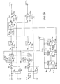
- Fig. 3A shows an example of a circuit for measuring the relative flow in two pipes. Operational amplifiers
- U 1 and U 6 are used as integrators. Their action is controlled by switches S 1 , S 2 , S 4 and S 5 . Opamps U 2 and U 7 select the positive going wave and turn on switches S 1 and S 4 respectively to permit integration over the positive portion.
- U 1 and U 6 integrate for a period determined by timer U 10 . At suitable intervals the charge on C 1 and C 3 is dumped by switches S 2 and S S . Prior to this, the peak value of the integrated signals is sampled by S3 and S 6 respectively and integrated by R 5 -C 2 and R 8 -C 4 combinations to yield the second integral. The switching and sampling is controlled by timer U 10 and one-shots U 11 and U 12 .
- U 4 takes the average of the two signals by acting as a summer with gain of 1 ⁇ 2 to each signal.
- the divider circuits, U 5 and U 9 take the ratio of each signal to their average.
- Fig. 3B the RMS and configuration, U 13 and U 14 , amplify the signals appropriately and present them to RMS converters U 15 and U 16 .
- U 17 takes the average and U 18 and U 19 compare the individual signals to the averages.
- Typical available circuits used for: U 1 ,U 2 ,U 3 , U 4 ,U 6 ,U 7 ,U 8 ,U 13 , U 14 ,U 17 is the National LF 356; for U 5 ,U 9 ,U 18 ,U 19 the Analog Devices AD535; for U 10 the National LM555; for U 11 ,U 12 the Motorola MC 14538; for U 15 ,U 16 the Analog Devices AD 536A; and for S 1 ,S 2 ,S 3 ,S 4 ,S 5 and S 6 the RCA CD 4066 B.
- Fig. 5 shows one embodiment of the electrode or sensor 26 for picking up the electrode static/triboelectric charge of particles passing in the pipe 10.
- the electrode 26 comprises, in the embodiment as shown in Fig. 5, two electrode plates 56 which extend around approximately 180° of the pipe 10 and are electrically insulated from the pipe by insulation 58.
- Each electrode plate 56 is about D/2 in axial length on the axis of pipe 10, with the center to center spacing of plates 56 being about 3D,where D is pipe diameter.
- Such electrode pairs can be used for determining the pc velocity by correlation of the induced signals.
- Fig. 6 shows an alternative form of the sensor 26 wherein a rod electrode 60 is utilized,which is mounted in an insulating mounting 62 and has a ball 64 for receiving the charge amount from the flow of pulverized coal within pipe 10.
- Fig. 7 shows the use of a Faraday cage type sensor comprising two spaced apart rings 70, 70 which are each electrically insulated from pipe 10 by insulation 72. Electroplates 70, 70 each have an axial length of about D/2 with a center to center spacing of about 3D, where D is pipe diameter.
- Such electrode pairs can be used for determining the pc velocity by correlation of the induced signals.
Landscapes
- Physics & Mathematics (AREA)
- Fluid Mechanics (AREA)
- General Physics & Mathematics (AREA)
- Chemical & Material Sciences (AREA)
- Chemical Kinetics & Catalysis (AREA)
- Electrochemistry (AREA)
- Measuring Volume Flow (AREA)
- Other Investigation Or Analysis Of Materials By Electrical Means (AREA)
Applications Claiming Priority (2)
| Application Number | Priority Date | Filing Date | Title |
|---|---|---|---|
| US556524 | 1983-11-30 | ||
| US06/556,524 US4512200A (en) | 1983-11-30 | 1983-11-30 | Pulverized coal relative distribution meter |
Publications (2)
| Publication Number | Publication Date |
|---|---|
| EP0144193A2 true EP0144193A2 (fr) | 1985-06-12 |
| EP0144193A3 EP0144193A3 (fr) | 1987-01-07 |
Family
ID=24221704
Family Applications (1)
| Application Number | Title | Priority Date | Filing Date |
|---|---|---|---|
| EP84308069A Ceased EP0144193A3 (fr) | 1983-11-30 | 1984-11-21 | Mesure des débits relatifs de charbon pulvérisé |
Country Status (7)
| Country | Link |
|---|---|
| US (1) | US4512200A (fr) |
| EP (1) | EP0144193A3 (fr) |
| JP (1) | JPS60200125A (fr) |
| KR (1) | KR890001933B1 (fr) |
| BR (1) | BR8405878A (fr) |
| CA (1) | CA1211215A (fr) |
| ES (1) | ES8604689A1 (fr) |
Cited By (4)
| Publication number | Priority date | Publication date | Assignee | Title |
|---|---|---|---|---|
| GB2266772A (en) * | 1992-04-30 | 1993-11-10 | Pollution Control & Measuremen | Detecting particles in a gas flow triboelectrically. |
| US5753632A (en) * | 1993-04-07 | 1998-05-19 | Schmidt; Alfred | Use of colloidal silica for the treatment of sickle-cell anaemia, malaria and exogenously induced leucopenias |
| US6192740B1 (en) | 1993-04-06 | 2001-02-27 | Pcme Limited | Method and apparatus for detecting particles in a flow |
| CN103827584A (zh) * | 2011-07-13 | 2014-05-28 | 普美康过程控制和测量技术康拉德有限责任公司 | 用于在燃煤电厂燃烧设备中煤粉燃烧过程中控制燃料空气比的装置和方法 |
Families Citing this family (20)
| Publication number | Priority date | Publication date | Assignee | Title |
|---|---|---|---|---|
| US4714890A (en) * | 1984-10-09 | 1987-12-22 | Auburn International, Inc. | Flow measuring apparatus with analog, essentially linear output |
| US4882934A (en) * | 1986-03-12 | 1989-11-28 | Charles B. Leffert | Ultrasonic instrument to measure the gas velocity and/or the solids loading in a flowing gas stream |
| US4726235A (en) * | 1986-03-12 | 1988-02-23 | Available Energy, Inc. | Ultrasonic instrument to measure the gas velocity and/or the solids loading in a flowing gas stream |
| US5102281A (en) * | 1989-04-13 | 1992-04-07 | Halliburton Company | Automatic rate matching system |
| US5004400A (en) * | 1989-04-13 | 1991-04-02 | Halliburton Company | Automatic rate matching system |
| US5022274A (en) * | 1990-01-22 | 1991-06-11 | University Of Pittsburgh | High temperature particle velocity meter and associated method |
| DE19504544A1 (de) * | 1995-02-11 | 1996-08-14 | Reich Ernst | Verfahren zum Ermitteln der Beladung eines Gasstroms mit Feststoffanteilen |
| GB2307989B (en) * | 1995-12-07 | 1999-07-07 | Abb Kent Taylor Ltd | Improvements in flow metering |
| JP2003057200A (ja) * | 2001-08-20 | 2003-02-26 | Kansai Ootomeishiyon Kk | 粉粒体の濃度計測装置 |
| US6799525B2 (en) * | 2002-09-13 | 2004-10-05 | General Electric Company | Automatic coal damper |
| AT500674B1 (de) * | 2003-04-10 | 2007-01-15 | Univ Graz Tech | Vorrichtung zum messen der strömungsgeschwindigkeit eines massenflusses |
| US20070000416A1 (en) * | 2005-06-30 | 2007-01-04 | General Electric Company | Method and System for controlling coal flow |
| US20070095260A1 (en) * | 2005-10-31 | 2007-05-03 | Foster Wheeler Energy Corporation | On-line adjustable coal flow distributing device |
| RU2391634C2 (ru) * | 2006-12-20 | 2010-06-10 | Открытое акционерное общество "Шестая генерирующая компания оптового рынка электроэнергии" (ОАО "ОГК-6") | Способ измерения расхода и калорийности потока угольной пыли и устройство для его осуществления |
| US20110197831A1 (en) * | 2007-04-13 | 2011-08-18 | Babcock-Hitachi Kabushiki Kaisha | Pulverized Coal Burning Boiler |
| US20100218591A1 (en) * | 2007-06-21 | 2010-09-02 | Rhodes George W | Method and apparatus for controlling relative coal flow in pipes from a pulverizer |
| DE102008030650B4 (de) * | 2008-06-27 | 2011-06-16 | PROMECON Prozeß- und Meßtechnik Conrads GmbH | Einrichtung und Verfahren zur Steuerung des Brennstoff-Luft-Verhältnisses bei der Verbrennung gemahlener Kohle in einer Kohlekraftwerksfeuerungsanlage |
| US20150292737A1 (en) * | 2012-10-11 | 2015-10-15 | Ecomb Ab (Publ) | Supply device for a combustion chamber |
| RU2550596C1 (ru) * | 2013-12-11 | 2015-05-10 | Открытое Акционерное Общество "Сибтехэнерго"-инженерная фирма по наладке, совершенствованию технологий и эксплуатации электро-энергооборудования предприятий и систем | Способ измерения массового расхода вещества в потоке |
| CN106771047B (zh) * | 2016-12-16 | 2023-08-29 | 华北电力大学 | 一种基于多传感器的煤粉含水率和煤种监测装置及方法 |
Family Cites Families (7)
| Publication number | Priority date | Publication date | Assignee | Title |
|---|---|---|---|---|
| US3176513A (en) * | 1962-03-29 | 1965-04-06 | Western Electric Co | Feeding and metering the flow of fluent material through a conduit |
| US3359796A (en) * | 1964-01-23 | 1967-12-26 | Univ Illinois | Apparatus for measuring mass flow using a shielded probe |
| CH541149A (de) * | 1971-06-22 | 1973-08-31 | Berweger Erwin | Bewegungselektrischer Wandler |
| GB2063482B (en) * | 1979-11-08 | 1983-09-14 | Hashim Al Rabeh R | Fluid velocity meter |
| DE3042661A1 (de) * | 1980-11-12 | 1982-06-16 | Waeschle Maschinenfabrik Gmbh, 7980 Ravensburg | Verfahren und anlage zur versorgung mehrerer brenner einer feuerungsanlage mit koernigem oder pulverfoermigem brennstoff |
| JPS57207826A (en) * | 1981-06-17 | 1982-12-20 | Hideo Nagasaka | Measuring device for flow rate of pulverulent body |
| FR2516234B1 (fr) * | 1981-11-06 | 1985-07-19 | Esswein Sa | Dispositif de detection de l'ecoulement d'un produit pulverulent ou granuleux circulant dans un conduit isolant et appareil comportant un tel dispositif |
-
1983
- 1983-11-30 US US06/556,524 patent/US4512200A/en not_active Expired - Fee Related
-
1984
- 1984-10-31 CA CA000466712A patent/CA1211215A/fr not_active Expired
- 1984-11-05 ES ES84537388A patent/ES8604689A1/es not_active Expired
- 1984-11-19 BR BR8405878A patent/BR8405878A/pt unknown
- 1984-11-21 EP EP84308069A patent/EP0144193A3/fr not_active Ceased
- 1984-11-26 JP JP59248298A patent/JPS60200125A/ja active Granted
- 1984-11-28 KR KR1019840007472A patent/KR890001933B1/ko not_active Expired
Cited By (6)
| Publication number | Priority date | Publication date | Assignee | Title |
|---|---|---|---|---|
| GB2266772A (en) * | 1992-04-30 | 1993-11-10 | Pollution Control & Measuremen | Detecting particles in a gas flow triboelectrically. |
| GB2266772B (en) * | 1992-04-30 | 1995-10-25 | Pollution Control & Measuremen | Detecting particles in a gas flow |
| US6192740B1 (en) | 1993-04-06 | 2001-02-27 | Pcme Limited | Method and apparatus for detecting particles in a flow |
| US5753632A (en) * | 1993-04-07 | 1998-05-19 | Schmidt; Alfred | Use of colloidal silica for the treatment of sickle-cell anaemia, malaria and exogenously induced leucopenias |
| CN103827584A (zh) * | 2011-07-13 | 2014-05-28 | 普美康过程控制和测量技术康拉德有限责任公司 | 用于在燃煤电厂燃烧设备中煤粉燃烧过程中控制燃料空气比的装置和方法 |
| CN103827584B (zh) * | 2011-07-13 | 2016-01-13 | 普美康过程控制和测量技术康拉德有限责任公司 | 用于在燃煤电厂燃烧设备中煤粉燃烧过程中控制燃料空气比的装置和方法 |
Also Published As
| Publication number | Publication date |
|---|---|
| KR850004801A (ko) | 1985-07-27 |
| KR890001933B1 (ko) | 1989-05-31 |
| CA1211215A (fr) | 1986-09-09 |
| JPH0516536B2 (fr) | 1993-03-04 |
| BR8405878A (pt) | 1985-09-17 |
| EP0144193A3 (fr) | 1987-01-07 |
| JPS60200125A (ja) | 1985-10-09 |
| US4512200A (en) | 1985-04-23 |
| ES537388A0 (es) | 1986-02-01 |
| ES8604689A1 (es) | 1986-02-01 |
Similar Documents
| Publication | Publication Date | Title |
|---|---|---|
| US4512200A (en) | Pulverized coal relative distribution meter | |
| US3635082A (en) | Apparatus for measuring mass flow of fluidborne solids | |
| Qian et al. | Measurement of the mass flow and velocity distributions of pulverized fuel in primary air pipes using electrostatic sensing techniques | |
| EP0829014B1 (fr) | Systeme de mesure et procede de detection d'electricite statique et/ou d'une variation de cette derniere dans un instrument de mesure et leurs utilisations | |
| Hammer et al. | The spatial filtering effect of capacitance transducer electrodes (flow measurement) | |
| EP0693178B1 (fr) | Procede et appareil de detection de particules dans un flux | |
| US5022274A (en) | High temperature particle velocity meter and associated method | |
| Zheng et al. | Online measurement of the size distribution of pneumatically conveyed particles through acoustic emission detection and triboelectric sensing | |
| US6865495B2 (en) | Flow metering | |
| JP2008519260A (ja) | イオンバランスモニタ | |
| US6305231B1 (en) | Flow metering | |
| CN102236028B (zh) | 粉粒体的流动计测装置 | |
| Cheng et al. | Electrical Measurement of Flow Rate of Pulverized Coal Suspension | |
| Coulthard et al. | Online pulverised-fuel monitoring at Methil power station | |
| Gajewski | Measuring probes, head, and system for the non-contact, electrostatic measurements of the two-phase flow parameters in pneumatic transport of solids | |
| GB2063482A (en) | Fluid Velocity Meter | |
| Kuštrin et al. | An electrostatic measuring technique for monitoring particle size in dilute pneumatic transport | |
| Abrar et al. | Solids velocity measurement using electric capacitance sensor assemblies | |
| CN116221759A (zh) | 一种基于多参数在线测量的煤粉均衡调节系统 | |
| Zhang et al. | A Study of Electrostatic Charges on Pneumatically Conveyed Solids | |
| CN119468246A (zh) | 一次风粉浓度测量装置、方法及供热系统 | |
| JPH06137918A (ja) | 微粉炭流量の計測方法 | |
| Zhang et al. | Measuring and controlling pulverized fuel on coal-fired plant | |
| JPS55125414A (en) | Device for detecting distribution of flowing speed in pipeline of conductive fluid | |
| KR100770283B1 (ko) | 분립체의 농도 계측 장치 |
Legal Events
| Date | Code | Title | Description |
|---|---|---|---|
| PUAI | Public reference made under article 153(3) epc to a published international application that has entered the european phase |
Free format text: ORIGINAL CODE: 0009012 |
|
| AK | Designated contracting states |
Designated state(s): DE FR NL |
|
| PUAL | Search report despatched |
Free format text: ORIGINAL CODE: 0009013 |
|
| AK | Designated contracting states |
Kind code of ref document: A3 Designated state(s): DE FR NL |
|
| 17P | Request for examination filed |
Effective date: 19870514 |
|
| 17Q | First examination report despatched |
Effective date: 19881108 |
|
| RBV | Designated contracting states (corrected) |
Designated state(s): DE FR |
|
| STAA | Information on the status of an ep patent application or granted ep patent |
Free format text: STATUS: THE APPLICATION HAS BEEN REFUSED |
|
| 18R | Application refused |
Effective date: 19900506 |
|
| RIN1 | Information on inventor provided before grant (corrected) |
Inventor name: GHERING, WALTER L. Inventor name: THOMPSON, WILLIAM LEE |