EP0144232A2 - Dispositif de pesage automatique - Google Patents
Dispositif de pesage automatique Download PDFInfo
- Publication number
- EP0144232A2 EP0144232A2 EP84308384A EP84308384A EP0144232A2 EP 0144232 A2 EP0144232 A2 EP 0144232A2 EP 84308384 A EP84308384 A EP 84308384A EP 84308384 A EP84308384 A EP 84308384A EP 0144232 A2 EP0144232 A2 EP 0144232A2
- Authority
- EP
- European Patent Office
- Prior art keywords
- weighing
- weighing hopper
- load sensor
- hopper
- automatic
- Prior art date
- Legal status (The legal status is an assumption and is not a legal conclusion. Google has not performed a legal analysis and makes no representation as to the accuracy of the status listed.)
- Granted
Links
- 238000005303 weighing Methods 0.000 title claims abstract description 148
- 230000005611 electricity Effects 0.000 abstract description 13
- 230000003068 static effect Effects 0.000 abstract description 13
- 125000006850 spacer group Chemical group 0.000 description 5
- 230000002411 adverse Effects 0.000 description 2
- 238000010276 construction Methods 0.000 description 2
- 239000012212 insulator Substances 0.000 description 2
- 230000004048 modification Effects 0.000 description 2
- 238000012986 modification Methods 0.000 description 2
- 238000007599 discharging Methods 0.000 description 1
- 238000006073 displacement reaction Methods 0.000 description 1
- 230000000694 effects Effects 0.000 description 1
- 238000009413 insulation Methods 0.000 description 1
- 239000000463 material Substances 0.000 description 1
- 238000004806 packaging method and process Methods 0.000 description 1
- 229920003002 synthetic resin Polymers 0.000 description 1
- 239000000057 synthetic resin Substances 0.000 description 1
- XLYOFNOQVPJJNP-UHFFFAOYSA-N water Substances O XLYOFNOQVPJJNP-UHFFFAOYSA-N 0.000 description 1
Images


Classifications
-
- G—PHYSICS
- G01—MEASURING; TESTING
- G01G—WEIGHING
- G01G3/00—Weighing apparatus characterised by the use of elastically-deformable members, e.g. spring balances
- G01G3/12—Weighing apparatus characterised by the use of elastically-deformable members, e.g. spring balances wherein the weighing element is in the form of a solid body stressed by pressure or tension during weighing
- G01G3/14—Weighing apparatus characterised by the use of elastically-deformable members, e.g. spring balances wherein the weighing element is in the form of a solid body stressed by pressure or tension during weighing measuring variations of electrical resistance
- G01G3/1414—Arrangements for correcting or for compensating for unwanted effects
-
- G—PHYSICS
- G01—MEASURING; TESTING
- G01G—WEIGHING
- G01G13/00—Weighing apparatus with automatic feed or discharge for weighing-out batches of material
- G01G13/003—Details; specially adapted accessories
-
- G—PHYSICS
- G01—MEASURING; TESTING
- G01G—WEIGHING
- G01G19/00—Weighing apparatus or methods adapted for special purposes not provided for in the preceding groups
- G01G19/387—Weighing apparatus or methods adapted for special purposes not provided for in the preceding groups for combinatorial weighing, i.e. selecting a combination of articles whose total weight or number is closest to a desired value
- G01G19/393—Weighing apparatus or methods adapted for special purposes not provided for in the preceding groups for combinatorial weighing, i.e. selecting a combination of articles whose total weight or number is closest to a desired value using two or more weighing units
-
- G—PHYSICS
- G01—MEASURING; TESTING
- G01G—WEIGHING
- G01G21/00—Details of weighing apparatus
- G01G21/22—Weigh pans or other weighing receptacles; Weighing platforms
Definitions
- This invention relates to an automatic weighing apparatus having a plurality of weighing machines.
- An automatic weighing apparatus now in practical use operates by supplying articles to a plurality of weighing machines, computing combinations of weight values obtained from the weighing machines, selecting a combination of the weight values the sum total whereof is equal to a predetermined fixed weight, and discharging only the articles contained in the weighing machines corresponding to the selected combination (referred to as the "optimum combination"), whereby there is obtained a batch of the articles the weight whereof is equal or closest to the fixed weight.
- Each weighing machine in an automatic weighing apparatus of the above type is composed of a weighing hopper in which the articles to be weighed are introduced, and a load sensor coupled to the weighing hopper.
- the load sensor generally makes use of a load cell utilizing strain gauges and is so adapted that the weight of the articles introduced into the weighing hopper is delivered as an output in the form of an electric signal.
- the output signal of the load cell is of extremely small magnitude. Therefore, depending upon the site at which the automatic weighing apparatus is installed, there are cases where noise is produced in the output signal owing to the influence of external radio waves.
- the weighing hopper acts as an antenna with respect to the external radio waves, so that noise produced in the weighing hopper owing to these radio waves is transmitted to the load cell, thereby enlarging the noise component in the output signal of the load cell. The end result is a weighing error.
- the weighing hopper may , depending upon the nature of the articles being weighed, develop a large amount of static electricity owing to friction between the articles and the weighing hopper when the articles are introduced into or discharged from the hopper.
- This static electricity may build up on the weighing hopper until the hopper is charged to a high voltage.
- noise ascribable to the discharge is introduced into the output signal of the load sensor when the discharge occurs. This also results in a weighing error.
- a high voltage may be inflicted upon and thus damage a DC amplifier that amplifies the load cell signal.
- an automatic weighing apparatus having a plurality of weighing machines each of which comprises a weighing hopper and a load sensor, wherein the apparatus is so adapted that noise produced in the weighing hopper will not be transmitted to the load sensor.
- an automatic weighing apparatus having a plurality of weighing machines each of which comprises a weighing hopper and a load sensor, wherein the apparatus is so adapted that noise produced in the weighing hopper owing to external radio waves will not be transmitted to the load sensor.
- an embodiment of the invention can provide an automatic weighing apparatus in which high-voltage static electricity will not build up on weighing hoppers.
- an automatic weighing apparatus having a plurality of weighing machines each of which comprises a weighing hopper and a load sensor, wherein the load sensor of each weighing machine includes means for removing a noise component produced in the weighing hopper of the weighing machine.
- an automatic weighing apparatus having a plurality of weighing machines each of which comprises a weighing hopper and a load sensor, wherein the weighing hopper of each weighing machine is connected to the load Sensor of the weighing machine via an insulating member.
- an automatic weighing apparatus adapted so that when a gate actuating device, which is disposed for each weighing hopper and connected to ground, actuates a gate of the corresponding weighing hopper, the latter is electrically connected to the gate actuating device.
- a gate actuating device which is disposed for each weighing hopper and connected to ground, actuates a gate of the corresponding weighing hopper, the latter is electrically connected to the gate actuating device.
- the weighing hopper is grounded each time the gate thereof is opened or closed by the grounded actuating device, static electricity which builds up on the weighing hopper owing to friction between the hopper and the articles being weighed can be sent to ground each time the weighing hopper gate is opened or closed. This can prevent the occurrence of weighing errors and other failures even in an automatic weighing apparatus which handles articles that readily produce static electricity.
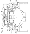
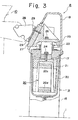
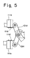
- Figs. 1 through 3 illustrate a first embodiment of the present invention, in which Fig. 1 is a longitudinal sectional view showing an automatic weighing apparatus in its entirety, Fig. 2 is a longitudinal sectional front view of a weighing machine body in the weighing apparatus of Fig. 1, and Fig. 3 is a longitudinal sectional side view taken along line III-III of Fig. 2, Fig. 4 is a side view showing a principal portion of a second embodiment of the present invention, and Fig. 5 is a side view showing a principal portion of a modification of the second embodiment of the present invention.
- Figs. 1 through 3 illustrate a first embodiment of an automatic weighing apparatus according to the present invention.
- the automatic weighing apparatus has a base 1 above which a platform 2 is supported by a plurality of support legs la. Disposed at the central portion of the platform 2 is a dispersing table 4 supported by a vibrating device 3 arranged on the platform 2. Disposed radially along the perimeter of the dispersing table 4 are a plurality of supply troughs 6. Each supply trough 6 is supported on the platform 2 by a corresponding vibrating device 5. Disposed below the ends of the supply troughs 6 are pool hoppers 7 each of which corresponds to one of the troughs 6. Each pool hopper 7 is attached to the outer circumferential portion of the platform 2. A plurality of weighing machines 8 arrayed in a circle are disposed below corresponding ones of the pool hoppers 7.
- Each weighing machine 8 is mounted on the base 1 and comprises a main body 9 incorporating a load sensor, and a weighing hopper 10 mounted on the main body 9.
- Each weighing hopper 10 is provided with an inwardly opening gate 10a and an outwardly opening gate 10b in the illustrated embodiment.
- a plurality of gate actuating devices 11 are attached to an depend from the lower side of the platform 2. Each gate actuating device 11 corresponds to one cooperating set of the pool hoppers 7 and weighing hoppers 10. Each gate actuating device 11 is adapted so as to be operated by a motor 12 mounted on the lower side of the platform 2. When a command to discharge weighed articles is received from a computation control unit, not shown, the gate actuating device 11 thrusts push rods lla, llb, llc outwardly of the device to open the gates lOb, 10a of the corresponding weighing hopper 10 and a gate 7a of the pool hopper 7.
- Collecting chutes 13 are disposed beneath the weighing hoppers 10, In the illustrated embodiment, the collecting chutes 13 are equipped with two collecting routes, namely a route corresponding to the inwardly opening gates 10a of the weighing hoppers 10, and a route corresponding to the outwardly opening gates 10b of the weighing hoppers 10.
- the main body 9 of the weighing machine 8 comprises a generally U-shaped base 15 secured to the base 1 by bolts 14, a ceiling plate 17 spanning the upper end portions of the base 15 and secured thereto by bolts 16, and a cover 18 covering the top of the ceiling plate 17.
- the main body 9 houses a load cell 20 serving as a load sensor and supported by a bracket 19 depending from the bottom side of the ceiling plate 17 at one edge thereof.
- the load cell 20 comprises a fixed end portion 20a connected to the bracket 19, a movable end portion 20b on the side opposite the fixed end portion 20a, and upper and lower beams 20c, 20d interconnecting the end portions 20a, 20b.
- the beams 20c, 20d have resilient portions 20e provided at two locations thereof.
- the load cell 20 has a movable bracket 21 fixedly provided on its movable end portion and is connected via the movable bracket 21, a support post 23, a junction member 25 and a spacer 27 to bracket 28 on which the weighing hopper 10 is mounted.
- the support post 23 penetrates a hole 22 provided at the central portion of the ceiling plate 17 and has a lower end fixedly secured to the movable bracket 21 by a bolt 24, and an upper end connected to the junction member 25 by bolts 26.
- the weighing hopper mounting bracket 28 is attached to the junction member 25 by a bolt 29 via a spacer 27.
- the combined weight of the weighing hopper 10 and the articles within the weighing hopper thus acts upon the movable end portion of the load cell 20 via the mounting bracket 28, spacer 27, junction member 25, support post 23 and movable bracket 21.
- the load cell 20, which is thus arranged so that a load will act upon the movable end portion 20b thereof, senses the load electrically by an output signal produced by the aforementioned bridge circuit.
- the output signal conforms to the amount of flexure of the flexible portions 20e experienced by the upper and lower beams 20c, 20d, the amount of flexure corresponding in turn to the applied load.
- an insulating member consisting of synthetic resin or the like constitutes the support post 23, which supports the weighing hopper 10 via the weighing hopper mounting bracket 28, spacer 27 and junction member 25.
- the weighing hopper 10 and load cell 20 are thus electrically isolated from each other by means of the support post 23.
- the member formed of an insulator is not limited to the support post 23, for it will suffice if an insulator is used to construct any one of the mechanical members interconnecting the weighing hopper 10 and load cell 20, such as the weighing hopper mounting bracket 28, junction member 25, support post 23 and movable bracket 21. In other words, what is important is that the weighing hopper 10 and load cell 20 be electrically isolated from each other by way of insulation.
- the load cell 20 is housed within the case 30 mounted on the lower side of the ceiling plate 17, and the arrangement is such that the load cell 20 is protected against water and humidity by a dehumidifying material (not-shown) sealed so as not to contact the load cell.
- Numeral 33 denotes calibrating means disposed on the side portion of the junction member 25 and comprising a solenoid 31 and a weight 32 for applying a load to the junction member 25 when the solenoid is rendered conductive.
- Numeral 34 designates adjustable limit setting means mounted on the ceiling plate 17 for preventing excessive flexure of the load cell 20 by limiting displacement of the movable bracket 21 so as not to exceed a predetermined value.
- the articles to be weighed are fed dispersively from the dispersing table 4 to the weighing hoppers 10 via the troughs 6 and pool hoppers 7.
- the load of the articles in each weighing hopper 10 is applied to the movable end portion of the corresponding load cell 20 through the weighing hopper mounting bracket 28, spacer 27, junction member 25, support post 23 and movable bracket 21.
- the weight of the article batch in each weighing hopper 10 is thus weighed.
- the computation control unit which is not shown, selects from the resulting weight values an optimum combination of weight values for obtaining a predetermined, fixed weight.
- the articles belonging to the selected combination are released into the underlying collecting chutes 13 by opening, via the gate actuating devices 11, the gates 10a or 10b of tie weighing hoppers 10 corresponding to the selected combination. These articles are then supplied t: a packaging apparatus (not shown) upon being collected in one of the collecting routes. Those weighing hoppers 10 that have discharged their articles are immediately resupplied for the next weighing cycle from the overlying pool hoppers 7 by opening the gates of these pool hoppers through operation of the corresponding gate actuating devices 11.
- the automatic weighing apparatus If the automatic weighing apparatus is installed at a location where there are strong radio waves, the weighing hoppers 10 of the respective weighing machines 8 act as antennae with respect to these radio waves.
- the weighing hoppers 10 transmit these radio waves to the load cells 20 serving as the load sensors, whereby noise is produced in the load cell output signals.
- the support post 23 joining the weighing hopper 10 and load cell 20 of each weighing machine 8 is constituted by an insulating member, so that the hopper and cell are electrically insulated. Accordingly, radio waves picked up by the weighing hopper 10 are prevented from being transmitted to the load cell 20. This prevents noise from being produced in the output of the load cell 20 and thus solves the problem of weighing errors resulting from radio waves.
- FIG. 4 A second embodiment of an automatic weighing apparatus according to the present invention will now be described with reference to Figs. 4 and 5.
- the basic construction is similar to that of the first embodiment, and the weighing hopper and load sensor (load cell) of each weighing machine are similarly electrically isolated from each other.
- electrically conductive members form weighing hopper push rods 110a, 110b of each gate actuating device 110, and operating members 100c, 100d of a gate actuating link mechanism of each weighing hopper 100.
- the push rod 110a or 110b is brought into contact with the operating member 100c or 100d to open the gate 100a or 100b, the weighing hopper 100 and gate actuating device 110 conduct electrically so that the weighing hopper 100 will be grounded via the gate actuating device 110.
- the weighing hopper 100 of a weighing machine 80 is isolated with respect to the load sensor of weighing machine main body 90, static electricity which accumulates on the weighing hopper 100 due to friction between the weighing hopper and certain weighed articles when the articles are supplied or discharged is not allowed to build up to a high voltage.
- the weighing hopper 100 is grounded via the gate actuating device 110 or base whenever the gate 100a or 100b is opened or closed.
- the load sensors of the automatic weighing apparatus according to the present embodiment are thus freed of adverse effects caused by discharge of high-voltage static electricity which has built up on the weighing hoppers 100.
- Fig. 5 illustrates a modification of the second embodiment.
- brushes llld are attached to push rods llla, lllb of the gate actuating device, and the arrangement is such that the brushes llld will contact the operating members lOlc, 101d on the weighing hopper side when the gates are opened or closed.
- an automatic weighing apparatus of the type described in which the adverse influence of radio wave jamming or of static electricity upon each of the weighing machines can be prevented.
Landscapes
- Physics & Mathematics (AREA)
- General Physics & Mathematics (AREA)
- Weight Measurement For Supplying Or Discharging Of Specified Amounts Of Material (AREA)
Applications Claiming Priority (2)
| Application Number | Priority Date | Filing Date | Title |
|---|---|---|---|
| JP22869783A JPS60120222A (ja) | 1983-12-03 | 1983-12-03 | 計量装置 |
| JP228697/83 | 1983-12-03 |
Publications (3)
| Publication Number | Publication Date |
|---|---|
| EP0144232A2 true EP0144232A2 (fr) | 1985-06-12 |
| EP0144232A3 EP0144232A3 (en) | 1986-04-23 |
| EP0144232B1 EP0144232B1 (fr) | 1989-10-11 |
Family
ID=16880378
Family Applications (1)
| Application Number | Title | Priority Date | Filing Date |
|---|---|---|---|
| EP19840308384 Expired EP0144232B1 (fr) | 1983-12-03 | 1984-12-03 | Dispositif de pesage automatique |
Country Status (3)
| Country | Link |
|---|---|
| EP (1) | EP0144232B1 (fr) |
| JP (1) | JPS60120222A (fr) |
| DE (1) | DE3480116D1 (fr) |
Cited By (4)
| Publication number | Priority date | Publication date | Assignee | Title |
|---|---|---|---|---|
| EP0261951A3 (en) * | 1986-09-26 | 1989-05-10 | Tokyo Electric Co. Ltd. | Electronic appliance |
| EP0302691A3 (fr) * | 1987-08-01 | 1990-05-16 | Ishida Scales Mfg. Co. Ltd. | Dispositif de pesage |
| DE3933764A1 (de) * | 1989-10-10 | 1991-04-18 | Eberhard Jost | Einrichtung zum bestimmen des spezifischen gewichts leichter schuettgueter |
| DE4203739A1 (de) * | 1992-02-09 | 1993-08-12 | Conpro Gmbh | Verwiegeeinrichtung |
Families Citing this family (1)
| Publication number | Priority date | Publication date | Assignee | Title |
|---|---|---|---|---|
| CN104048742B (zh) * | 2014-05-31 | 2016-07-06 | 新安中联万基水泥有限公司 | 一种水泥生产专用计量平台 |
Family Cites Families (7)
| Publication number | Priority date | Publication date | Assignee | Title |
|---|---|---|---|---|
| CH488174A (de) * | 1968-08-19 | 1970-03-31 | Sartorius Werke Gmbh | Explosionsschutz für die Beleuchtungseinrichtung einer Waage |
| GB2003284A (en) * | 1977-08-05 | 1979-03-07 | Woodman Co | Conveyor cut-off gate |
| DE2906669A1 (de) * | 1979-02-21 | 1980-09-04 | Bizerba Werke Kraut Kg Wilh | Schaltanordnung zur verringerung elektrischer stoereinfluesse auf elektromechanische waagen |
| FR2492095A2 (fr) * | 1979-03-15 | 1982-04-16 | Perrier Gerard | Balance, notamment pese-personne |
| AU541709B2 (en) * | 1981-08-18 | 1985-01-17 | K.K. Ishida Koki Seisakusho | Combinatorial weighing apparatus |
| DE3205799A1 (de) * | 1982-02-18 | 1983-08-25 | Sartorius GmbH, 3400 Göttingen | Oberschalige elektronische waage |
| JPS59161040U (ja) * | 1983-04-13 | 1984-10-29 | アサノ精機株式会社 | ロ−ドセル秤の保護装置 |
-
1983
- 1983-12-03 JP JP22869783A patent/JPS60120222A/ja active Granted
-
1984
- 1984-12-03 EP EP19840308384 patent/EP0144232B1/fr not_active Expired
- 1984-12-03 DE DE8484308384T patent/DE3480116D1/de not_active Expired
Cited By (5)
| Publication number | Priority date | Publication date | Assignee | Title |
|---|---|---|---|---|
| EP0261951A3 (en) * | 1986-09-26 | 1989-05-10 | Tokyo Electric Co. Ltd. | Electronic appliance |
| EP0302691A3 (fr) * | 1987-08-01 | 1990-05-16 | Ishida Scales Mfg. Co. Ltd. | Dispositif de pesage |
| DE3933764A1 (de) * | 1989-10-10 | 1991-04-18 | Eberhard Jost | Einrichtung zum bestimmen des spezifischen gewichts leichter schuettgueter |
| DE4203739A1 (de) * | 1992-02-09 | 1993-08-12 | Conpro Gmbh | Verwiegeeinrichtung |
| EP0555759B2 (fr) † | 1992-02-09 | 2000-08-09 | CONPRO GmbH | Débimètre massique |
Also Published As
| Publication number | Publication date |
|---|---|
| EP0144232A3 (en) | 1986-04-23 |
| JPH0442607B2 (fr) | 1992-07-14 |
| DE3480116D1 (en) | 1989-11-16 |
| JPS60120222A (ja) | 1985-06-27 |
| EP0144232B1 (fr) | 1989-10-11 |
Similar Documents
| Publication | Publication Date | Title |
|---|---|---|
| US4573542A (en) | Load-weighing apparatus for an elevator car | |
| US4280576A (en) | Low profile tension mounted load cell industrial scale | |
| CA1128983A (fr) | Sous-station transportable | |
| EP0122796B1 (fr) | Balance | |
| EP0144232B1 (fr) | Dispositif de pesage automatique | |
| EP0125902A2 (fr) | Récipiant pour un dispositif de pesage automatique | |
| EP0164839A3 (fr) | Balances | |
| CA2644875A1 (fr) | Mesure de la charge sur roue et/ou par essieu des vehicules routiers | |
| US4266624A (en) | Weighing apparatus | |
| NZ195335A (en) | Livestock weighing apparatus:platform supported on load beams | |
| US20130228384A1 (en) | Weighing Unit and Combination Weigher Using the Same | |
| EP0422288B1 (fr) | Contrôleur de poids | |
| EP0362567A3 (fr) | Dispositif étanche pour le pesage automatique | |
| CA1084959A (fr) | Balance a plate-forme basse s'adaptant aux irregularites de la surface support | |
| EP1111353B1 (fr) | Dispositif de pesage | |
| US4350218A (en) | Weigh-platform, resting on load measuring support points | |
| Bandyopadhyay | Seismic Fragility of Nuclear Power Plant Components:(phase 1) | |
| US4852673A (en) | Weighing apparatus with radio interference protection | |
| EP0210005A3 (fr) | Système de pesage combinatoire | |
| EP0076113B1 (fr) | Dispositif de pesage avec une série de machines de pesage | |
| US4085850A (en) | Single load cell weigh hopper system | |
| GB2178179A (en) | Vehicle weighing apparatus | |
| JPS6335381Y2 (fr) | ||
| US4618013A (en) | Combination weighing machine with auxiliary weight hopper | |
| US7514640B2 (en) | Load beam for a weighing apparatus |
Legal Events
| Date | Code | Title | Description |
|---|---|---|---|
| PUAI | Public reference made under article 153(3) epc to a published international application that has entered the european phase |
Free format text: ORIGINAL CODE: 0009012 |
|
| AK | Designated contracting states |
Designated state(s): DE FR GB IT NL |
|
| PUAL | Search report despatched |
Free format text: ORIGINAL CODE: 0009013 |
|
| AK | Designated contracting states |
Kind code of ref document: A3 Designated state(s): DE FR GB IT NL |
|
| 17P | Request for examination filed |
Effective date: 19860910 |
|
| 17Q | First examination report despatched |
Effective date: 19870923 |
|
| GRAA | (expected) grant |
Free format text: ORIGINAL CODE: 0009210 |
|
| AK | Designated contracting states |
Kind code of ref document: B1 Designated state(s): DE FR GB IT NL |
|
| PGFP | Annual fee paid to national office [announced via postgrant information from national office to epo] |
Ref country code: DE Payment date: 19891109 Year of fee payment: 6 |
|
| REF | Corresponds to: |
Ref document number: 3480116 Country of ref document: DE Date of ref document: 19891116 |
|
| PGFP | Annual fee paid to national office [announced via postgrant information from national office to epo] |
Ref country code: GB Payment date: 19891130 Year of fee payment: 6 Ref country code: FR Payment date: 19891130 Year of fee payment: 6 |
|
| ET | Fr: translation filed | ||
| PGFP | Annual fee paid to national office [announced via postgrant information from national office to epo] |
Ref country code: NL Payment date: 19891231 Year of fee payment: 6 |
|
| ITF | It: translation for a ep patent filed | ||
| PLBE | No opposition filed within time limit |
Free format text: ORIGINAL CODE: 0009261 |
|
| STAA | Information on the status of an ep patent application or granted ep patent |
Free format text: STATUS: NO OPPOSITION FILED WITHIN TIME LIMIT |
|
| 26N | No opposition filed | ||
| PG25 | Lapsed in a contracting state [announced via postgrant information from national office to epo] |
Ref country code: GB Effective date: 19901203 |
|
| PG25 | Lapsed in a contracting state [announced via postgrant information from national office to epo] |
Ref country code: NL Effective date: 19910701 |
|
| GBPC | Gb: european patent ceased through non-payment of renewal fee | ||
| NLV4 | Nl: lapsed or anulled due to non-payment of the annual fee | ||
| PG25 | Lapsed in a contracting state [announced via postgrant information from national office to epo] |
Ref country code: FR Effective date: 19910830 |
|
| PG25 | Lapsed in a contracting state [announced via postgrant information from national office to epo] |
Ref country code: DE Effective date: 19910903 |
|
| REG | Reference to a national code |
Ref country code: FR Ref legal event code: ST |