EP0144433A1 - Dispositif de combustion - Google Patents
Dispositif de combustion Download PDFInfo
- Publication number
- EP0144433A1 EP0144433A1 EP84901435A EP84901435A EP0144433A1 EP 0144433 A1 EP0144433 A1 EP 0144433A1 EP 84901435 A EP84901435 A EP 84901435A EP 84901435 A EP84901435 A EP 84901435A EP 0144433 A1 EP0144433 A1 EP 0144433A1
- Authority
- EP
- European Patent Office
- Prior art keywords
- sensor
- ignition
- burner
- circuit
- combustion
- Prior art date
- Legal status (The legal status is an assumption and is not a legal conclusion. Google has not performed a legal analysis and makes no representation as to the accuracy of the status listed.)
- Granted
Links
Images






Classifications
-
- F—MECHANICAL ENGINEERING; LIGHTING; HEATING; WEAPONS; BLASTING
- F23—COMBUSTION APPARATUS; COMBUSTION PROCESSES
- F23N—REGULATING OR CONTROLLING COMBUSTION
- F23N5/00—Systems for controlling combustion
- F23N5/003—Systems for controlling combustion using detectors sensitive to combustion gas properties
- F23N5/006—Systems for controlling combustion using detectors sensitive to combustion gas properties the detector being sensitive to oxygen
-
- Y—GENERAL TAGGING OF NEW TECHNOLOGICAL DEVELOPMENTS; GENERAL TAGGING OF CROSS-SECTIONAL TECHNOLOGIES SPANNING OVER SEVERAL SECTIONS OF THE IPC; TECHNICAL SUBJECTS COVERED BY FORMER USPC CROSS-REFERENCE ART COLLECTIONS [XRACs] AND DIGESTS
- Y02—TECHNOLOGIES OR APPLICATIONS FOR MITIGATION OR ADAPTATION AGAINST CLIMATE CHANGE
- Y02E—REDUCTION OF GREENHOUSE GAS [GHG] EMISSIONS, RELATED TO ENERGY GENERATION, TRANSMISSION OR DISTRIBUTION
- Y02E20/00—Combustion technologies with mitigation potential
- Y02E20/34—Indirect CO2mitigation, i.e. by acting on non CO2directly related matters of the process, e.g. pre-heating or heat recovery
Definitions
- the present invention has an object of taking safety measures by the employment of an oxygen concentration cell type sensor for detecting incomplete combustion in a combustor such as petroleum, gas fan heater, stove or the like.
- a sensor of an oxygen concentration cell type such as a zirconia sensor is generally known as a sensor for detecting the incomplete combustion and is put into practical use in a combustor using gas as fuel.
- the zirconia sensor has characteristics in that electromotive force suddenly changes at an air fuel ratio (hereinafter referred to as M value) M ⁇ 1 as shown in Fig. 1 in high temperature atmosphere and the inner resistance reduces due to the temperature rise as shown in Fig. 2. Accordingly, it is used also as a sensor, with the use of the temperature characteristics, for detecting an accidental fire as well as the ignition.
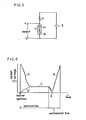
- Fig. 3 shows one example of the detecting circuit.
- 1 is a zirconia sensor, which is made equivalent with the electromotive force e i and the inner resistance Ri. 2 is connected to a DC power supply 3 with a series resistance connected in series to the zirconia sensor 1 and becomes a voltage impression type to the sensor.
- the a, b show detection output terminals, respectively.
- the inner resistance Ri becomes several hundreds megohms, which is sufficiently larger than the series resistance 2, and the output electric potential becomes almost the same to the current power supply 3.
- the inner resistance Ri lowers through the rise in temperature, becomes a value sufficiently smaller than the series resistance 2, and the divided voltage potential through the series resistance 2 and the inner resistance Ri drops as-shown with a solid line A of Fig. 4 to an extremely small value. Accordingly, the detection of the drop voltage can indicate that the burner caught fire.
- the conventional construction is uneconomical in power consumption as the voltage is normally applied upon the sensor and the power supply circuit is required to impress the stabilized voltage to the sensor to positively detect the ignition because of large dispersion of the inner resistance of the sensor so that a power-supply stabilizing circuit is required, thus resulting in complicated construction and higher cost.
- a first object of the present invention is to ignite the burner, in a condition where the voltage application is not performed upon the sensor, in a range, i.e., a low air fuel ratio (hereinafter referred to as a low M value) smaller than 1 in the air fuel thereby to remove the above-described problems, that is, to ensure the ignition detection and to improve the economy and cost.
- a low air fuel ratio hereinafter referred to as a low M value
- a second object of the present invention is to reduce the production amount of the carbon monoxide as much as possible by the movement of the burner combustion to the normal M value simultaneously with the ignition detection.
- a third object of the present invention is to preheat the sensor to try to shorten the time required for the ignition detection.
- the temperature of the sensor falls when an accidental fire occurs for some cause, so that the inner resistance Ri becomes 100 megohms as before the combustion and the output potential abruptly rises as far as the approximately same value as that of the DC power supply 3 as shown with a solid line B of Fig. 4. Accordingly, the accident fire of the burner can be detected through the detection of the voltage rise.
- the changes in the electromotive force of the sensor itself are required to be used as an accidental signal in a type in which the voltage is not applied upon the sensor, the electromotive force hardly changes as shown with a broken line B' of Fig. 4 when the burner is being burned in a normal M value condition of 1.0 or more in M value.
- a fourth object of the present invention is in that the voltage is not applied upon the sensor during the burner ignition, the voltage-is applied upon the sensor after the lapse of given time to enable the accidental fire to be positively detected.
- the burning condition of the burner is detected by a sensor of an oxygen concentration cell type to ignite the burner at a low air fuel ratio
- an ignition detecting circuit is provided to detect as an ignition signal the output of the sensor to be thus generated
- the ratio is adapted to be switched from the low air fuel ratio to the normal air fuel ratio in accordance with the output of the ignition detecting signal from the ignition detecting circuit.
- the senor is adapted to be preheated in advance before the start of the combustion.
- the voltage is adapted to be applied upon the sensor after the lapse of the given time without being applied upon the sensor at the burner ignition.
- the present invention has big effects in that the ignition error hardly exists and the positive ignition is ensured, because the ignition is performed at a low M value, i.e., at dense mixed gas.
- the senor As the sensor is preheated in advance by a preheater and is ignited in a low M value, the sensor produces big electromotive force simultaneously with the ignition of the burner to momentarily detect the ignition to switch the value into a normal M value. Accordingly, the amount of the carbon monoxide or the like to be produced during the ignition detection becomes extremely small, which ensures the higher safety.
- the voltage is adapted to be applied upon the sensor after the lapse of the given time without being applied upon the sensor at the burner ignition, the output from the sensor abruptly changes because of change in the inner resistance when an accidental fire occurs in the burner. Accordingly, the accidental detection can be performed by the use of the output change and a combustion apparatus high in safety can be provided.
- Fig. 1 is a characteristic graph of the output of an oxygen concentration cell type sensor for detecting incomplete combustion.
- Fig. 2 is a temperature characteristic graph of the sensor.
- Fig. 3 is a circuit diagram for the conventional incomplete combustion detection and ignition detection.
- Fig. 4 is a characteristic chart of the sensor output in the same circuit.
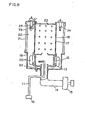
- Fig. 5 is a cross-sectional view of a combustion apparatus in a first embodiment of the present invention.
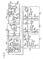
- Fig. 6 is a circuit diagram in the same embodiment.
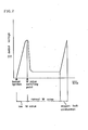
- Fig. 7 is an output characteristic chart of the sensor in the same embodiment.
- Fig. 8 is a cross-sectional view of a combustion apparatus in a second embodiment of the present invention.
- Fig. 9 is an output characteristic chart in the embodiment.
- Fig. 10 is a circuit diagram in a third embodiment of the present invention.
- Fig. 11 is an output characteristic chart of the sensor in the same embodiment.
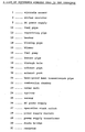
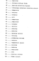
- Fig. 5 shows one example of a combustion apparatus of petroleum as fuel, wherein 11 is a fuel pipe, 12 is a vaporizing pipe for vaporizing the fuel from the fuel pipe 11, 13 is a heater for preheating the vaporizing pipe 12, 14 is a blowing pipe for feeding the air for combustion use into the vaporizing pipe 13, 15 is a blower, 16 is a fuel pump, 17 is a burner pipe disposed on the vaporizing pipe, 18 is a through hole formed in the burner pipe, 19 is an exhaust pipe disposed to surround the outer periphery of the vaporizing pipe 12, 20 is an exhaust port, 21 is a heat-proof heat transmission pipe, 22 is a combustion chamber formed between the heat-proof heat transmission pipe 21 and the burner pipe 17, 23 is a cover unit covering the burner pipe 17 and the heat-proof heat transmission pipe 21, 24 is an igniter mounted on the cover unit 23, 25 is a sensor for detecting the incompletion combustion mounted on the cover unit 23.
- FIG. 6 is an AC power supply, which is applied upon a power supply transformer 29 of a power supply circuit 28 through an operation start switch 27.
- the power supply circuit 28 has the output of the transformer 29 rectified by a diode bridge 30 so that it is smoothed and made constant in voltage by a resistor 31, a capacitor 32, a constant voltage diode 33, and feeds DC power to each type of control circuit.
- the output potential a of the sensor 25 outputs a signal to an ignition detecting circuit 35 and a combustion condition detecting circuit 36.
- the potential a is inputted to a negative input terminal of a comparator 37 of the ignition detecting circuit 35 and is compared with the partial pressure potential b of the resistors 38, 39 inputted to the positive input terminal to produce the output c.
- the output c of the comparator 37 is connected to the power supply circuit 28 through the coil 40 of the relay Ry 2 and is connected to the b potential through a positive feedback resistor 34.
- a combustion condition detecting circuit 36 has the output potential a of the sensor 25 compared respectively with the potentials d, e, divided in voltage through the resistors 45, 46, 47, by a comparator 43 thereby -to construct a wind comparator circuit.
- the output f of the comparators 43, 44 is pulled up by the resistor 48 and is inputted to the inverter circuit 49 thereby producing the output potential g. 51 shows a preheating circuit of a heater 13 for preheating the vaporizing pipe 12 (Fig. 5).
- the division-voltage potential h, of the resistor 52 and the temperature sensor 53 (where a negative characteristic temperature-sensing resistance element is used) of the vaporizing pipe 12 is compared with the division-voltage potential i of the resistors 54, 55 thereby providing an output potential j.
- the output j of the comparator 56 is connected to the power supply circuit 28 through the coil 57 of the relay Ry 3 and is inputted to an inverter circuit 58.
- the output of the inverter circuit 58 is connected to the division-pressure potential k of the resistor 60 and the capacitor 61 of the timer circuit 59, a timer circuit 59 compares the potential k with the division-voltage k of the resistors 62, 63 by a comparator 64, and the output m is connected to the coil 65 of the relay Ry 1 and is connected to the anode of the diode 66.
- the cathode of the diode is connected to the output potential g of the combustion condition detecting circuit 36.
- an igniting circuit 67 is connected to the AC power supply 26.
- An igniting circuit 67 is supplied with power by a series circuit of an operation switch 27, a stop switch 68 connected in parallel to it, and a contact 67 of the relay Ry 1.
- An igniter 24 is connected to the NC contact of a first contact 70 of the relay Ry 2 and a motor 71 for driving a blowing fan (not shown) of the hot water.
- a fuel pump 16 and a blower 15 for combustion use are connected to the contact 72 of the relay Ry 3.
- the blower 15 for combustion use allows the Hi-Lo switching operation of the blowing amount to be effected, which is switched by a second contact 70' of the relay Ry 2.
- 13 shows a heater for preheating the vaporizing pipe 12.
- the comparators 37, 43, 44, 56, 64 described here use the comparator of the generally known two input open collector output, the inverter circuits 49, 58 also use the inverter of the open collector output.
- the atmosphere temperature of the sensor is equal to a room temperature
- the inner resistor Ri is as large as several hundreds megohms in impedance and the electromotive force e i is also zero.
- a becomes smaller than b as compared with the reference potential b
- the output c of the comparator 37 becomes Hi output.
- the comparator 37 is the open collector output as described hereinabove
- the output Hi is equal to the open and the coil 40 of the relay Ry 2 is not energized. Accordingly, both the contacts 70, 70' are retained at a contact NC and the igniter 24 is energized.
- the electric potential b becomes the division-pressure electric potential of a resistor 38, the impedance of the coil 40 of the relay Ry 2 in parallel to it, a parallel circuit of a resistor 34 and a resistor 39.
- the resistance value of the temperature sensor 53 becomes larger so that the potential h becomes larger than i because of low temperature of an initial evaporator, the output j of the comparator 56 is Hi, and the relay Ry 3 57 is not conducted, either.
- the pump 16 and the blower 15 are not operated.
- the output of the inverter 58 becomes Lo output to prevent the capacitor 61 of the timer circuit 59 from being charged.
- the potential k becomes almost zero volt and the output m of the comparator 64 becomes Lo output, because the electric potential k is smaller than 1. Therefore, the relay Ry 1 is conducted and the power keeps feeding by a contact 69 if the operation switch 27 is released. Namely, at the early stage, the heater 13 and the igniter 24 operate to perform the heating operation.
- the electric potential h drops to approach the potential i.
- the potential i is designed to become equal to the potential h at a time when the temperature of the evaporizing pipe has become a temperature at which the fuel can be evaporated, and the comparator 56 becomes Lo output, when the potential h has become smaller than the i or equal to the i, to conduct the relay Ry 3.
- the fuel pump 16 and the blower 15 are operated.
- the blower 15 becomes lower in an amount and the fuel to be fed from the fuel pump 16 causes the air amount to be lower than the required air amount. Namely, it is a low M value at which dense mixed gas is fed to improve the ignition performance.
- the inverter 58 becomes a Hi output (open), and the capacitor 61 of the timer circuit 59 begins to be charged through a resistor 60.
- the comparator 64 becomes Hi output at a time point, when the potential k has become larger than A or equal to l because of the charging of the capacitor 61, to cut off the relay Ry 1 to stop the operation.
- the coil of the relay Ry 1 is conducted through a diode 66 to be described later, and continues its conduction, even if the output m of the comparator 64 becomes Hi, to cause the combustion to be continued.
- the atmosphere temperature of the sensor 25 rises through the heating operation of the burner so that the sensor 25 becomes detectable.
- the sensor 25, which is an oxygen concentration cell, produces electromotive force in accordance with the oxygen density in the combustion exhaust gas when the atmosphere temperature of the sensor is higher than the sensor operation temperature. Namely, the electromotive force of about 0.8 V is produced when the air amount (low M value) has become less than the theory air amount of the burner, and the electromotive force becomes almost zero when the air has become excessive.
- the combustion condition becomes equal to a kind of incomplete combustion, and the sensor senses it as shown in Fig. 7 to output the electromotive force e.
- the electromotive force is caused, when the burner has been ignited, to allow the ignition detection to be performed.
- the ignition detecting circuit 35 detects the electro-motive force to cause the combustion to move into the normal M value condition. Namely, when the electromotive force e i of the sensor 25 becomes higher than the potential b of the ignition detecting circuit 35, the output c of the comparator 37 becomes Lo output to energize the coil 40 of the relay Ry 2.
- the contact 70 is switched from the NC side to the NO side to stop the operation of the igniter 24 to drive the fan motor 71 thereby releasing the hot air into the room and simultaneously the contact 70' of the relay Ry 2 is also switched onto the NO side to turn the burner motor 15 into Hi airflow.
- the combustion airflow suitable for the supply fuel of the pump 16 comes to be fed and the combustion moves to the normal M value combustion.
- the burner returns to the normal M value combustion and the electromotive force e i of the sensor 25 also lowers, the output c retains Lo by the positive feedback resistor 34 of the comparator 37.
- the comparator 37 becomes Lo output, and simultaneously the potential b' becomes the division-pressure potential of the resistor 39, the parallel resistance of the resistor 34, and the resistor 38 and becomes a sufficiently low value as compared with the b potential at a time when the output c of the comparator 37 is in the Hi. If the electromotive force e. of the sensor 25 lowers, the output c retains the Lo to keep the potential a larger than b'.
- the combustion condition detecting circuit 36 compares a potential equal to the electromotive force e i of the sensor 25 with potentials d, e by comparators 43, 44 to detect the combustion condition thereby stopping the combustion when the incomplete combustion is occurred.
- Fig. 8 shows a second embodiment of the present invention, which is different from the above-described embodiment in that the preheating heater 79 for heating the sensor 25 in advance before the combustion start is provided.
- a preheating heater 79 is required to be electrically connected in parallel to the ignition transformer 24.
- the burner becomes equal to a kind of incomplete combustion simultaneously with the ignition and the sensor 25 detects it to produce the electromotive force, but the sensor 25 is heated in advance by a preheating heater 79 into a detectable condition so that the large electromotive force is produced simultaneously with the ignition of the burner as shown in Fig. 9A. Accordingly, the ignition detection is momentarily performed.
- the ignition detecting circuit 35 detects the large electromotive force of the sensor 25 to move the combustion to the normal M value combustion as described hereinabove, but as the sensor 25 is adapted to be sufficiently heated with the heat from the burner at this time, the current flowing to the preheating heater 79 is turned off to save the energy.
- an igniter of a heater type is used as an igniter 24 and is provided close to the sensor 25 so that the sensor 25 may be preheated with the igniter 24.
- FIG. 10 A third embodiment of the present invention will be described with reference to Fig. 10.
- voltage is not applied upon the sensor at the ignition time, but the voltage is adapted to be applied upon the sensor after the given time period.
- 73 shows a sensor which obtains the output of the sensor 25, and a series resistor 74, a switching transistor 75 are connected in series to the sensor, and the base of the transistor 75 is connected to the output c of the comparator 37 of the ignition detecting circuit 35 through the resistor 76.
- 77 shows the emitter base resistor of the transistor 75.
- the preheating heater 79 is connected in parallel to the igniter 24.
- the inner resistance Ri is as large in impedance as several hundreds megohms and the electromotive force e i is also zero as shown in Fig. 7A.
- a is smaller than b as compared with the reference potential b and the output .
- c of the comparator 37 becomea a Hi output.
- the comparator 37 is an open collector output as described hereinabove, the output Hi is equal to the open, the current does not flow to the relay Ry 2 coil 40.
- both contacts 70, 70' are maintained at the NC contact and the preheating heater 79 of the igniter 24 and the sensor 25 are energized.
- the resistance value of the temperature sensor 53 is large because of the low temperature of the initial vaporizing pipe, the potential h becomes larger than i, the output i of the comparator 56 is Hi and the relay Ry 3 57 is not also conducted. Accordingly, the pump 16 and the blower 15 do not operate.
- the output of the inverter 58 becomes Lo to prevent the capacitor 61 of the timer circuit 59 from being charged.
- the potential k becomes almost zero in voltage, and the output m of the comparator 64 becomes Lo output, because the potential k is smaller than 1. Consequently, the relay Ry 1 is conducted to keep feeding the power with the contact 69 even if the operation switch 27 is released.
- the heater 13, the igniter 24 and the heater 79 for sensor use are operated to perform the preheating operation.
- the potential h lowers and approaches the potential i.
- the potential i is designed to become equal to the potential h available at the temperature of the vaporizing pipe wherein the fuel can be vaporized, and when the potential h has become smaller than i or has become equal to i, the comparator 56 becomes Lo in output to cause the relay Ry 3 to conduct.
- the fuel pump 16 and the blower 15 operate.
- the blower 15 becomes low in air amount and the air amount is smaller than the air amount required for the fuel to be fed from the fuel pump 16.
- the mixed gas which is of a low M value and is dense is fed to improve the ignition performance.
- the output c of the comparator 37 is Hi and thus the transistor 75 of the sensor circuit 73 does not conduct so that the power from the power supply circuit 31 is not fed to the sensor 25. Accordingly, the comparator 37 keeps detecting only the electromotive force e i of the sensor 25 when the output j of the comparator 56 becomes Lo, the inverter 58 becomes Hi output (open), the charging operation starts through the resistor 60 into the capacitor 61 of the timer circuit 59, and the comparator 64 becomes Hi in output, at a time point when the potential k has become larger than 1 or has become equal to 1, to energize the coil 65 of the relay Ry 1 to cut off the contact 69 thereby stopping the operation.
- the combustion condition detecting circuit 36 compares and decides the output from the sensor 25 to keep flowing the current to the coil 65 of the relay Ry 1 through the diode 66 to continue the combustion. At this time, the sensor 25 produces the electromotive force momentarily to shorten the ignition detection.
- the sensor 25 detects it to produce the electromotive force, but as the sensor 25 is heated in advance by the preheating heater 73 and becomes detectable as described hereinabove, the large electromotive force is produced simultaneously with the ignition of the burner as shown in Fig. 11B. Accordingly, the ignition detection is momentarily performed.
- the ignition detecting circuit 35 detects the large electromotive force of the sensor 25 (higher than the potential b) produced in such a manner as described hereinabove, the output of the comparator 37 becomes Lo to energize the coil 40 of the relay Ry 2. Hence, the contact 70' is switched onto the NO side to get the blower 15 brought into the Hi air amount. Namely, the combustion air amount suitable for the supply fuel of the pump 16 comes to be fed for normal combustion to provide a condition wherein carbon monoxide or the like is not produced.
- the contact 70 of the relay Ry 2 is also switched from the NC side onto the NO side to stop the operation of the igniter 24 to drive a fan motor 71 thereby releasing the hot air into the chamber.
- the sensor 25 is adapted to be sufficiently heated with the heat from the burner, and thus the current flowing to the preheating heater 79 for heating the sensor 25 is turned off to save the power.
- the output c of the comparator 37 becomes Lo, the base current of the transistor 75 flows through the resistor 76 to cause the transistor 75 conductive.
- a series resistor 74 is connected in series with the sensor 25 and the current flows from the power supply circuit 28 to the sensor 25.
- the sensor 25 When the burner has suddenly had an accidental fire for some reasons, the sensor 25 outputs momentarily outputs an abnormal signal, but it is considered that an abnormal signal D is not produced depending upon the accidental fire conditions. Even if the abnormal signal is outputted, it is momentary so that it may not be detected by the detecting circuit.
- the inner resistance Ri suddenly rises due to the temperature drop of the sensor 25 even if the electromotive force e i is not caused during the burner accidental fire, so that the division-pressure potential of the series resistor 74 to be caused by the voltage application becomes a value (Fig. 11E) larger than the electromotive force e i .
- the potential from the sensor 25 with respect to the potential d of the combustion condition detecting circuit 36 becomes a ⁇ d to detect the accidental fire, and the relay 65 operates through the comparator 43, the inverter 49, the diode 66 to turn off the contact 69 and operates to stop the operation.
- the voltage application upon the sensor 25 may be automatically applied after the lapse of the given time period independently of the ignition detection.
Landscapes
- Engineering & Computer Science (AREA)
- Chemical & Material Sciences (AREA)
- Combustion & Propulsion (AREA)
- Mechanical Engineering (AREA)
- General Engineering & Computer Science (AREA)
- Regulation And Control Of Combustion (AREA)
- Control Of Combustion (AREA)
Abstract
Applications Claiming Priority (6)
| Application Number | Priority Date | Filing Date | Title |
|---|---|---|---|
| JP58069432A JPS59195031A (ja) | 1983-04-19 | 1983-04-19 | 燃焼装置 |
| JP69432/83 | 1983-04-19 | ||
| JP70332/83 | 1983-04-20 | ||
| JP58070332A JPS59195032A (ja) | 1983-04-20 | 1983-04-20 | 燃焼装置 |
| JP58094311A JPS59219626A (ja) | 1983-05-27 | 1983-05-27 | 燃焼装置 |
| JP94311/83 | 1983-05-27 |
Publications (3)
| Publication Number | Publication Date |
|---|---|
| EP0144433A1 true EP0144433A1 (fr) | 1985-06-19 |
| EP0144433A4 EP0144433A4 (fr) | 1985-09-02 |
| EP0144433B1 EP0144433B1 (fr) | 1988-10-26 |
Family
ID=27300043
Family Applications (1)
| Application Number | Title | Priority Date | Filing Date |
|---|---|---|---|
| EP84901435A Expired EP0144433B1 (fr) | 1983-04-19 | 1984-04-17 | Dispositif de combustion |
Country Status (4)
| Country | Link |
|---|---|
| US (1) | US4606719A (fr) |
| EP (1) | EP0144433B1 (fr) |
| DE (1) | DE3474851D1 (fr) |
| WO (1) | WO1984004150A1 (fr) |
Families Citing this family (4)
| Publication number | Priority date | Publication date | Assignee | Title |
|---|---|---|---|---|
| WO2009079931A1 (fr) * | 2007-12-21 | 2009-07-02 | Shenzhen H & T Intelligent Co., Ltd | Système de commande pour cuisinière à gaz |
| US8266885B2 (en) * | 2008-12-23 | 2012-09-18 | General Electric Company | Method and systems for adaptive ignition energy |
| JP2010230257A (ja) * | 2009-03-27 | 2010-10-14 | Dainichi Co Ltd | 燃焼装置 |
| US9175853B2 (en) | 2011-08-18 | 2015-11-03 | Aerco International, Inc. | Water heating system with oxygen sensor |
Family Cites Families (8)
| Publication number | Priority date | Publication date | Assignee | Title |
|---|---|---|---|---|
| IT1056864B (it) * | 1975-03-12 | 1982-02-20 | Friedrichsfeld Gmbh | Regolatore composito per bruciatori |
| JPS52126539A (en) * | 1976-04-15 | 1977-10-24 | Matsushita Electric Ind Co Ltd | Combustion safety device |
| JPS5812024Y2 (ja) * | 1978-03-14 | 1983-03-07 | 日本特殊陶業株式会社 | ガス燃焼機器の安全装置 |
| US4439138A (en) * | 1978-06-12 | 1984-03-27 | Aqua-Chem, Inc. | Combustion control apparatus |
| US4358265A (en) * | 1979-06-15 | 1982-11-09 | Matsushita Electric Industrial Co., Ltd. | Combustion appliance with a safety device |
| JPS5656527A (en) * | 1979-10-12 | 1981-05-18 | Matsushita Electric Ind Co Ltd | Combustion safety device |
| JPS5677624A (en) * | 1979-11-30 | 1981-06-26 | Rinnai Corp | Safety system for combusting apparatus |
| US4362499A (en) * | 1980-12-29 | 1982-12-07 | Fisher Controls Company, Inc. | Combustion control system and method |
-
1984
- 1984-04-17 DE DE8484901435T patent/DE3474851D1/de not_active Expired
- 1984-04-17 US US06/682,672 patent/US4606719A/en not_active Expired - Lifetime
- 1984-04-17 EP EP84901435A patent/EP0144433B1/fr not_active Expired
- 1984-04-17 WO PCT/JP1984/000194 patent/WO1984004150A1/fr not_active Ceased
Also Published As
| Publication number | Publication date |
|---|---|
| US4606719A (en) | 1986-08-19 |
| EP0144433A4 (fr) | 1985-09-02 |
| DE3474851D1 (en) | 1988-12-01 |
| WO1984004150A1 (fr) | 1984-10-25 |
| EP0144433B1 (fr) | 1988-10-26 |
Similar Documents
| Publication | Publication Date | Title |
|---|---|---|
| US4125356A (en) | Safety equipment for gas burner | |
| EP0071174B1 (fr) | Système d'allumage d'un brûleur et de détection de la flamme | |
| US5035607A (en) | Fuel burner having an intermittent pilot with pre-ignition testing | |
| CA2124039A1 (fr) | Circuit de detection d'intensite de flamme | |
| US4188181A (en) | Gas burner control system | |
| EP0271314A1 (fr) | Dispositif de commande d'une installation de chauffage pour une voiture | |
| US4606719A (en) | Combustion apparatus | |
| JPS6183825A (ja) | バ−ナ点火装置 | |
| GB2065345A (en) | Combustion safety apparatus | |
| US4778377A (en) | Device for controlling fuel combustion in a heater | |
| US4231732A (en) | Gas burner control system | |
| US4034235A (en) | Circuits | |
| CA1114040A (fr) | Circuit de stabilisation sur sonde-repere de flamme | |
| JPS6367609B2 (fr) | ||
| JPS631499B2 (fr) | ||
| US3762856A (en) | Burner ignition control system | |
| JPS6248134B2 (fr) | ||
| JPH0216144Y2 (fr) | ||
| US4591332A (en) | Control device of a combustion apparatus | |
| JPS59225221A (ja) | 燃焼装置 | |
| KR880004078Y1 (ko) | 연소 제어회로. | |
| JPS6248133B2 (fr) | ||
| KR900002677Y1 (ko) | 보일러의 자동점화 장치 | |
| JPS6243097B2 (fr) | ||
| US6890170B2 (en) | Heater with glow plug/flame monitor |
Legal Events
| Date | Code | Title | Description |
|---|---|---|---|
| PUAI | Public reference made under article 153(3) epc to a published international application that has entered the european phase |
Free format text: ORIGINAL CODE: 0009012 |
|
| 17P | Request for examination filed |
Effective date: 19850314 |
|
| AK | Designated contracting states |
Designated state(s): DE FR GB |
|
| 17Q | First examination report despatched |
Effective date: 19870505 |
|
| GRAA | (expected) grant |
Free format text: ORIGINAL CODE: 0009210 |
|
| AK | Designated contracting states |
Kind code of ref document: B1 Designated state(s): DE FR GB |
|
| REF | Corresponds to: |
Ref document number: 3474851 Country of ref document: DE Date of ref document: 19881201 |
|
| ET | Fr: translation filed | ||
| PLBE | No opposition filed within time limit |
Free format text: ORIGINAL CODE: 0009261 |
|
| STAA | Information on the status of an ep patent application or granted ep patent |
Free format text: STATUS: NO OPPOSITION FILED WITHIN TIME LIMIT |
|
| 26N | No opposition filed | ||
| REG | Reference to a national code |
Ref country code: GB Ref legal event code: 746 Effective date: 19960822 |
|
| PGFP | Annual fee paid to national office [announced via postgrant information from national office to epo] |
Ref country code: GB Payment date: 20000412 Year of fee payment: 17 |
|
| PGFP | Annual fee paid to national office [announced via postgrant information from national office to epo] |
Ref country code: FR Payment date: 20010409 Year of fee payment: 18 Ref country code: DE Payment date: 20010409 Year of fee payment: 18 |
|
| PG25 | Lapsed in a contracting state [announced via postgrant information from national office to epo] |
Ref country code: GB Free format text: LAPSE BECAUSE OF NON-PAYMENT OF DUE FEES Effective date: 20010417 |
|
| GBPC | Gb: european patent ceased through non-payment of renewal fee |
Effective date: 20010417 |
|
| PG25 | Lapsed in a contracting state [announced via postgrant information from national office to epo] |
Ref country code: DE Free format text: LAPSE BECAUSE OF NON-PAYMENT OF DUE FEES Effective date: 20021101 |
|
| PG25 | Lapsed in a contracting state [announced via postgrant information from national office to epo] |
Ref country code: FR Free format text: LAPSE BECAUSE OF NON-PAYMENT OF DUE FEES Effective date: 20021231 |
|
| REG | Reference to a national code |
Ref country code: FR Ref legal event code: ST |