EP0144439A1 - Mit flüssigkeit betriebener stellantrieb - Google Patents
Mit flüssigkeit betriebener stellantrieb Download PDFInfo
- Publication number
- EP0144439A1 EP0144439A1 EP84902056A EP84902056A EP0144439A1 EP 0144439 A1 EP0144439 A1 EP 0144439A1 EP 84902056 A EP84902056 A EP 84902056A EP 84902056 A EP84902056 A EP 84902056A EP 0144439 A1 EP0144439 A1 EP 0144439A1
- Authority
- EP
- European Patent Office
- Prior art keywords
- grooves
- tubes
- input
- output member
- output
- Prior art date
- Legal status (The legal status is an assumption and is not a legal conclusion. Google has not performed a legal analysis and makes no representation as to the accuracy of the status listed.)
- Granted
Links
Images


Classifications
-
- F—MECHANICAL ENGINEERING; LIGHTING; HEATING; WEAPONS; BLASTING
- F15—FLUID-PRESSURE ACTUATORS; HYDRAULICS OR PNEUMATICS IN GENERAL
- F15B—SYSTEMS ACTING BY MEANS OF FLUIDS IN GENERAL; FLUID-PRESSURE ACTUATORS, e.g. SERVOMOTORS; DETAILS OF FLUID-PRESSURE SYSTEMS, NOT OTHERWISE PROVIDED FOR
- F15B9/00—Servomotors with follow-up action, e.g. obtained by feed-back control, i.e. in which the position of the actuated member conforms with that of the controlling member
- F15B9/02—Servomotors with follow-up action, e.g. obtained by feed-back control, i.e. in which the position of the actuated member conforms with that of the controlling member with servomotors of the reciprocatable or oscillatable type
- F15B9/08—Servomotors with follow-up action, e.g. obtained by feed-back control, i.e. in which the position of the actuated member conforms with that of the controlling member with servomotors of the reciprocatable or oscillatable type controlled by valves affecting the fluid feed or the fluid outlet of the servomotor
- F15B9/09—Servomotors with follow-up action, e.g. obtained by feed-back control, i.e. in which the position of the actuated member conforms with that of the controlling member with servomotors of the reciprocatable or oscillatable type controlled by valves affecting the fluid feed or the fluid outlet of the servomotor with electrical control means
Definitions
- This invention relates to a hydraulic rotary actuator to be used for various kinds of industrial machines, instruments, and robbot, and the use of this actuator can provide very compact driving parts for wrists (hands) and fingers of robbots having such functions as selective positioning and control over power.
- an indispensable requisite for this purpose is to materialize a manipulator possessing such functions as positioning and clamping with high degree of freedom and in high precision.
- a hydraulic driving method using servo valves has widely been employee in the industrial field from the past but requires the provision of a pair of servo valves for each actuator.
- actuating oil must separately be fed to actuators and servo valves from the supply source and the structure of hydraulic pipe lines is complicated when a wrist of high degree of freedom is composed.
- the rotary actuator employing mechanical servos for controlling displacement, velocity, and power of the output shaft of the actuator pursuant to input signals has hitherto been used.
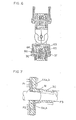
- Fig. 1 shows a conventional type rotary actuator as above, in which the application of reference numerals to parts is as follows:
- the input shaft 1 is slidably received within the output shaft 2 and a guide valve is formed between grooves on the surface of the input shaft 1 and other grooves on the inner surface of the guide valve sleeve 3 secured to the output shaft 2.
- the guide valve 4 opens as wide as proportionate to the angular deviation and the motor generates torque in the direction along which the deviation is compensated.
- the configuration and size of the guide valve 4 composed of the input shaft 1 and the guide valve sleeve 3 must be reduced and, therefore, the groove of guide valve 4 which exerts a great influence on characteristics of the servo system is difficult to be worked.
- FIG. 1 A conventional structure (Fig. 1), in which the input shaft 1 is contained within the output shaft 2 and thereby the end of the input shaft 1 on one side extends outside the actuator, has been followed by a problem that sliding torque of the sealing packing 9 for prevention of oil leakage is large and miniaturization of a motor (not shown) for driving the input shaft 1 is impossible.
- an arrangement of uncovered piping for actuating oil to be fed to actuators causes problems, as in the case of the abovesaid hydraulic drive by means of servo valves, in miniaturization and simplification of wrists having a high degree of freedom.
- Fig. 2 is a view of a hydraulic actuator embodying this invention, wherein the reference numeral 20 indicates an output shaft; 21, front plate; 22, rear plate; 23, cylinder; 24, stator of a pulse motor; 25, rotor; 26, cylindrical sleeve; 27, inner sun gear formed in said sleeve 26; 28, planet gear; 29, sun gear internally formed in said cylinder on the stationary side; 30, guide valve sleeve on the input side as an input member rotatably fitted on said output shaft 20; 31, bolt for rotatably fixing said planet gear 28 on the guide valve sleeve 30; 32, nut for fixedly securing said rotor 25 to said sleeve 26; 33, stationary vane formed integrally with said cylinder 23; 34, rotating vane formed integrally with said output shaft 20; 35 and 36, O-rings inserted between said output shaft 20 and two plates, that is, the front plate 24 and the rear plate 22, respectively; 36 and 37, screw-threaded parts on both ends of the output shaft 20; 38, bolt for
- the rotor 25 is fixed to the sleeve 26 by the nut 32, the sleeve 26 revolving in proportion to the number of input pulses of the pulse motor.
- the axis of the planet gear 28 is driven by the inner sun gear 27 formed on the sleeve 26 and rotates with the input side guide valve sleeve 30.
- Actuating oil is supplied to the vane chamber which is also an actuating chamber through passages as 41 ⁇ 43 ⁇ 44 ⁇ 45 and returned to the discharge side through passages as 51 - 50 -+ 48.
- Members 30 and 40 compose a guide valve of face-opposition type and are shown in Figs. 3 and 4, respectively, taken along the lines A - A and B - B in Fig. 2, respectively.
- the reference numerals 53a, -b, -c, and -d indicate shallow grooves formed circumferentially on the input side guide valve sleeve 30, and 54a, -b, -c, and -d are opening parts of passages 44a, 44b, 51a, .and 51b formed in the central part of the abovesaid grooves 53a, -c, -b, and -d, respectively, these grooves and openings being formed in four positions, every opposing two positions being symmetrical with respect to an axis.
- the numerals 55 and 56 indicate openings of the oil passage 52 on the low pressure side.
- 57 is a recess on the outer peripheral part of the output side guide valve plate 40; 28, recess on the inner peripheral part; 50, central projecting part; 60a, -b, -c, and -d, grooves formed on the projecting part 59 in four circumferential positions, every opposing two positions being symmetrical with respect to the axis; 61a and 61b are oil passage openings formed in said grooves 60a and 60b, respectively, and on the ends of the rotating vane 34 (shown by chain lines) so as to communicate with the vane chamber.
- Figs. 5(a) and 5(b) are views showing the principle of operation of the face-opposition type guide valve in an actuator according to this invention, the former showing a case in which an angular deviation occurs between the input side (corresponding to 30) and the output side (corresponding to 40) whereas the latter a case in which an angular deviation is 0° (at the time of end of positioning).
- the numerals 62a and 62b are valve chambers (actuating chambers) on the high pressure side and low pressure side, respectively.
- actuating oil is fed from passages connected to the oil supply side to the vane chamber 62a on the high pressure side through the course as 44a + 54a ⁇ 53a ⁇ 60a ⁇ 61a ⁇ 45 ⁇ 62a.
- the output shaft 20 rotates in the direction to eliminate the angular deviation (as shown by an arrow mark in Fig. 5(a)).
- Fig. 5(b) when an overlapping part between each groove on the input side and corresponding groove on the output side (for example, 53b and 60b) goes out, passages for oil supply and discharge are interrupted and the output shaft 20 stops rotating.
- a guide valve defined in this specification applies to the entire body formed of two members movable relative to each other so as to enable changeover and interruption of oil passages extending from the actuating oil supply source to the vane chamber as well as from the vane chamber to the oil discharge side.
- guide valve means a combination of a guide sleeve 30 on the input side with a guide valve plate 40 on the output side.
- Fig. 6 is a view showing a structure of a multijoint wrist of robbot in which hydraulic actuators according to this invention are connected with each other in the multi-step manner.
- the numerals 63, 64, and 65 indicate a housing, main oil passage on the supply side, and main oil passage on the discharge side, respectively.
- the housing 63 and output shaft 20 are fixed to each other by threaded parts 36 and 37 on both ends of the output shaft 20 and by nuts 66.
- Oil passages (corresponding to 63 and 64) for supply and discharge of oil formed within the housing 63 communicate with other oil passages (corresponding to 41, 43, 50, and 48 in Fig. 2) formed within the output shaft 20.
- This invention makes it possible to fabricate a hydraulic actuator remarkably compact and possessing high resolving power for positioning as compared with conventional type hydraulic actuators.
- a motor and reduction gears for driving the output part are incorporated into the actuator.
- a part of the input shaft 1 extends outside the hydraulic actuator, thereby causing a problem that, when a small motor is used, driving torque is insufficient due to sliding torque generated by sealing packing 9 for preventing leakage of actuating oil between the input shaft 1 and output shaft 2.
- sealing packing 9 for preventing leakage of actuating oil between the input shaft 1 and output shaft 2.
- members 26, 30, and 28 on the input side are disposed within the actuator, a packing as causing increase in sliding torque is not required. Accordingly, input torque is low and miniaturization of a motor is possible.
- a face-opposition type guide valve enables more reduction in size of an actuator body proper and improvement of servo characteristics.
- an outer peripheral recess 57 and inner peripheral recess 58 are formed on one end of the opposing faces of the guide valve and communication is established between these recesses and the passage 52 on the low pressure' side for mitigating thrust load f.
- opposing grooves 53a and 53c in pair as well as those 53b and 53d are symmetrically disposed with respect to the axial direction so that 53a and 53c are on the high pressure side as well.as 53b and 53d on the low pressure side for reducing a moment load M.
- grooves 60d and 60c are relationaless with supply and discharge in the actuating shaft and formed for the purpose of eliminating-the abovesaid moment load.
- the main passage 48 on the discharge side under low pressure communicates with the motor chamber 67 through the passage 68, whereby a thrust load exerted on the guide valve 30 from the right side (Fig. 2) is small.
- a guide valve is formed of thrust surfaces.
- a guide valve is formed so that a guide valve sleeve 30 and a guide valve plate 40 on the output side may have thrust surfaces thereof shaped as shown in Figs. 3 and 4, respectively, whereby opposing surfaces moving relative to each other are large in area and easily worked.
- a multi-step arrangement of actuators is possible, and hands and fingers of robbot can be composed to have a high degree of freedom and be simple and compact without complicated piping.
- This invention has successfully materialized a compact mechanical servo actuator endowed with a high resolving power for positioning.
- An application of a multi-step structure to actuators according to this invention is easy, and simple and compact structures of hands and fingers of robbot having high degree of freedom without complicated piping are also possible.
- An actuator according to this invention is widely utilized for various kinds of industrial robbots and industrial machines, thereby exhibiting highly significant effects.
Landscapes
- Engineering & Computer Science (AREA)
- Physics & Mathematics (AREA)
- Fluid Mechanics (AREA)
- Mechanical Engineering (AREA)
- General Engineering & Computer Science (AREA)
- Actuator (AREA)
- Servomotors (AREA)
Applications Claiming Priority (2)
| Application Number | Priority Date | Filing Date | Title |
|---|---|---|---|
| JP89456/83 | 1983-05-20 | ||
| JP58089456A JPS59217004A (ja) | 1983-05-20 | 1983-05-20 | 流体サ−ボアクチエ−タ |
Publications (3)
| Publication Number | Publication Date |
|---|---|
| EP0144439A1 true EP0144439A1 (de) | 1985-06-19 |
| EP0144439A4 EP0144439A4 (de) | 1985-09-26 |
| EP0144439B1 EP0144439B1 (de) | 1988-08-17 |
Family
ID=13971196
Family Applications (1)
| Application Number | Title | Priority Date | Filing Date |
|---|---|---|---|
| EP84902056A Expired EP0144439B1 (de) | 1983-05-20 | 1984-05-18 | Mit flüssigkeit betriebener stellantrieb |
Country Status (5)
| Country | Link |
|---|---|
| US (1) | US4646621A (de) |
| EP (1) | EP0144439B1 (de) |
| JP (1) | JPS59217004A (de) |
| DE (1) | DE3473495D1 (de) |
| WO (1) | WO1984004784A1 (de) |
Cited By (2)
| Publication number | Priority date | Publication date | Assignee | Title |
|---|---|---|---|---|
| EP0387533A3 (de) * | 1989-03-13 | 1991-04-10 | Hitachi, Ltd. | Direkt angetriebenes Servoventil, Druckmittel-Servoeinrichtung und Steuerungsverfahren für das direktangetriebene Servoventil |
| EP0540284A3 (en) * | 1991-10-28 | 1993-12-22 | Vickers Inc | Hydraulic piston pump with servo displacement control |
Families Citing this family (1)
| Publication number | Priority date | Publication date | Assignee | Title |
|---|---|---|---|---|
| DE4015101A1 (de) * | 1990-05-11 | 1991-11-14 | Eckehart Schulze | Hydraulische antriebsvorrichtung |
Family Cites Families (13)
| Publication number | Priority date | Publication date | Assignee | Title |
|---|---|---|---|---|
| GB500840A (de) * | ||||
| US2917079A (en) * | 1957-11-12 | 1959-12-15 | Gen Motors Corp | Fluid power steering control valve |
| US2988059A (en) * | 1958-05-08 | 1961-06-13 | Gen Motors Corp | Fluid power steering control valve |
| DE1262777B (de) * | 1962-09-12 | 1968-03-07 | Boelkow Gmbh | Hydraulischer Verstaerker, insbesondere hydraulisch kraftverstaerkter Stellantrieb |
| GB1093233A (en) * | 1964-04-06 | 1967-11-29 | Kawasaki Jyukogyo Kabushiki Ka | Hydraulic rotary servo mechanism |
| GB1393930A (en) * | 1971-12-29 | 1975-05-14 | Mitsubishi Metal Corp | Rotary type hydraulic servo-mechanism |
| JPS4945310A (de) * | 1972-09-08 | 1974-04-30 | ||
| JPS5310235B2 (de) * | 1972-10-21 | 1978-04-12 | ||
| JPS5532922B2 (de) * | 1973-03-31 | 1980-08-28 | ||
| US4177713A (en) * | 1975-05-12 | 1979-12-11 | The Garrett Corporation | Electrohydraulic proportional actuator apparatus |
| JPS5226310A (en) * | 1975-08-26 | 1977-02-26 | Kawasaki Steel Corp | Process for production of low-oxygen alloy steel by melting |
| JPS5491695A (en) * | 1977-12-16 | 1979-07-20 | Messerschmitt Boelkow Blohm | Digital servo motor |
| US4458580A (en) * | 1981-03-25 | 1984-07-10 | Jidosha Kiki Co., Ltd. | Power steering apparatus |
-
1983
- 1983-05-20 JP JP58089456A patent/JPS59217004A/ja active Pending
-
1984
- 1984-05-18 DE DE8484902056T patent/DE3473495D1/de not_active Expired
- 1984-05-18 WO PCT/JP1984/000249 patent/WO1984004784A1/ja not_active Ceased
- 1984-05-18 US US06/697,592 patent/US4646621A/en not_active Expired - Lifetime
- 1984-05-18 EP EP84902056A patent/EP0144439B1/de not_active Expired
Cited By (2)
| Publication number | Priority date | Publication date | Assignee | Title |
|---|---|---|---|---|
| EP0387533A3 (de) * | 1989-03-13 | 1991-04-10 | Hitachi, Ltd. | Direkt angetriebenes Servoventil, Druckmittel-Servoeinrichtung und Steuerungsverfahren für das direktangetriebene Servoventil |
| EP0540284A3 (en) * | 1991-10-28 | 1993-12-22 | Vickers Inc | Hydraulic piston pump with servo displacement control |
Also Published As
| Publication number | Publication date |
|---|---|
| DE3473495D1 (en) | 1988-09-22 |
| US4646621A (en) | 1987-03-03 |
| EP0144439A4 (de) | 1985-09-26 |
| EP0144439B1 (de) | 1988-08-17 |
| WO1984004784A1 (en) | 1984-12-06 |
| JPS59217004A (ja) | 1984-12-07 |
Similar Documents
| Publication | Publication Date | Title |
|---|---|---|
| US4232708A (en) | Fluid controller | |
| US4793433A (en) | Hydraulic reaction force apparatus for power steering system | |
| US4096766A (en) | Self-contained modular joint, notably for robots | |
| US4062601A (en) | Self-contained modular pivot, notably for robots | |
| US4435120A (en) | Arm for a programme controlled manipulator | |
| US4422344A (en) | Load proportional antibacklash gear drive system | |
| EP0144439A1 (de) | Mit flüssigkeit betriebener stellantrieb | |
| US5352163A (en) | Step-up or reduction gear series using internally meshing planetary gear structure | |
| US4492150A (en) | Actuator for mechanical apparatus | |
| US5090658A (en) | Bellows sealed rotary valve and seal assembly | |
| US5107754A (en) | Articulated mechanism with rotary vane motors | |
| US4781103A (en) | Fluid servomechanism | |
| US5261316A (en) | Angular displacement motor with counterbalance chambers | |
| KR100316751B1 (ko) | 스티어링제어유니트 | |
| US4655695A (en) | Rotating fluid driven rotary actuator | |
| US5228288A (en) | Control system for hydraulic rotary device | |
| KR960010223B1 (ko) | 고배압 동력조향장치 | |
| US4169404A (en) | Fluid pressure actuator | |
| JPH0372853B2 (de) | ||
| US4934205A (en) | Stepless speed change device | |
| GB2122263A (en) | Fluid-powered rotary actuator | |
| EP0901888A1 (de) | Rotationsausgleicher und roboter mit einer solchen rotationsausgleich-vorrichtung | |
| GB2048188A (en) | Rotary slide valve control device | |
| JPH0373758B2 (de) | ||
| JPS6044285A (ja) | ハンドリング装置 |
Legal Events
| Date | Code | Title | Description |
|---|---|---|---|
| PUAI | Public reference made under article 153(3) epc to a published international application that has entered the european phase |
Free format text: ORIGINAL CODE: 0009012 |
|
| 17P | Request for examination filed |
Effective date: 19850117 |
|
| AK | Designated contracting states |
Designated state(s): DE FR GB |
|
| 17Q | First examination report despatched |
Effective date: 19861120 |
|
| GRAA | (expected) grant |
Free format text: ORIGINAL CODE: 0009210 |
|
| AK | Designated contracting states |
Kind code of ref document: B1 Designated state(s): DE FR GB |
|
| REF | Corresponds to: |
Ref document number: 3473495 Country of ref document: DE Date of ref document: 19880922 |
|
| ET | Fr: translation filed | ||
| PLBE | No opposition filed within time limit |
Free format text: ORIGINAL CODE: 0009261 |
|
| STAA | Information on the status of an ep patent application or granted ep patent |
Free format text: STATUS: NO OPPOSITION FILED WITHIN TIME LIMIT |
|
| 26N | No opposition filed | ||
| PGFP | Annual fee paid to national office [announced via postgrant information from national office to epo] |
Ref country code: GB Payment date: 19950510 Year of fee payment: 12 Ref country code: FR Payment date: 19950510 Year of fee payment: 12 |
|
| PGFP | Annual fee paid to national office [announced via postgrant information from national office to epo] |
Ref country code: DE Payment date: 19950511 Year of fee payment: 12 |
|
| PG25 | Lapsed in a contracting state [announced via postgrant information from national office to epo] |
Ref country code: GB Effective date: 19960518 |
|
| GBPC | Gb: european patent ceased through non-payment of renewal fee |
Effective date: 19960518 |
|
| PG25 | Lapsed in a contracting state [announced via postgrant information from national office to epo] |
Ref country code: FR Effective date: 19970131 |
|
| PG25 | Lapsed in a contracting state [announced via postgrant information from national office to epo] |
Ref country code: DE Effective date: 19970201 |
|
| REG | Reference to a national code |
Ref country code: FR Ref legal event code: ST |