EP0144445B1 - Vorrichtung zum antreiben der objektivlinse eines optischen plattenspielers - Google Patents
Vorrichtung zum antreiben der objektivlinse eines optischen plattenspielers Download PDFInfo
- Publication number
- EP0144445B1 EP0144445B1 EP84902073A EP84902073A EP0144445B1 EP 0144445 B1 EP0144445 B1 EP 0144445B1 EP 84902073 A EP84902073 A EP 84902073A EP 84902073 A EP84902073 A EP 84902073A EP 0144445 B1 EP0144445 B1 EP 0144445B1
- Authority
- EP
- European Patent Office
- Prior art keywords
- holder
- driving
- objective lens
- focussing
- base
- Prior art date
- Legal status (The legal status is an assumption and is not a legal conclusion. Google has not performed a legal analysis and makes no representation as to the accuracy of the status listed.)
- Expired
Links
- 230000003287 optical effect Effects 0.000 title claims description 8
- 239000000696 magnetic material Substances 0.000 claims description 4
- 239000000463 material Substances 0.000 claims description 3
- 229910000906 Bronze Inorganic materials 0.000 claims description 2
- OAICVXFJPJFONN-UHFFFAOYSA-N Phosphorus Chemical compound [P] OAICVXFJPJFONN-UHFFFAOYSA-N 0.000 claims description 2
- DMFGNRRURHSENX-UHFFFAOYSA-N beryllium copper Chemical compound [Be].[Cu] DMFGNRRURHSENX-UHFFFAOYSA-N 0.000 claims description 2
- 239000010974 bronze Substances 0.000 claims description 2
- KUNSUQLRTQLHQQ-UHFFFAOYSA-N copper tin Chemical compound [Cu].[Sn] KUNSUQLRTQLHQQ-UHFFFAOYSA-N 0.000 claims description 2
- 230000003993 interaction Effects 0.000 claims description 2
- 229910001220 stainless steel Inorganic materials 0.000 claims description 2
- 239000003190 viscoelastic substance Substances 0.000 claims 1
- 238000004519 manufacturing process Methods 0.000 description 6
- 238000005476 soldering Methods 0.000 description 5
- 230000003247 decreasing effect Effects 0.000 description 3
- 238000010276 construction Methods 0.000 description 2
- 229910052751 metal Inorganic materials 0.000 description 2
- 239000002184 metal Substances 0.000 description 2
- 238000005245 sintering Methods 0.000 description 2
- 239000000758 substrate Substances 0.000 description 2
- 230000001052 transient effect Effects 0.000 description 2
- RYGMFSIKBFXOCR-UHFFFAOYSA-N Copper Chemical compound [Cu] RYGMFSIKBFXOCR-UHFFFAOYSA-N 0.000 description 1
- 230000000712 assembly Effects 0.000 description 1
- 238000000429 assembly Methods 0.000 description 1
- 230000015572 biosynthetic process Effects 0.000 description 1
- 239000004020 conductor Substances 0.000 description 1
- 239000011889 copper foil Substances 0.000 description 1
- 230000001627 detrimental effect Effects 0.000 description 1
- 238000006073 displacement reaction Methods 0.000 description 1
- 230000020169 heat generation Effects 0.000 description 1
- 230000001771 impaired effect Effects 0.000 description 1
- 238000003780 insertion Methods 0.000 description 1
- 230000037431 insertion Effects 0.000 description 1
- 238000005259 measurement Methods 0.000 description 1
- 238000000034 method Methods 0.000 description 1
- 238000000465 moulding Methods 0.000 description 1
- 230000010355 oscillation Effects 0.000 description 1
- 239000004033 plastic Substances 0.000 description 1
Images




Classifications
-
- G—PHYSICS
- G11—INFORMATION STORAGE
- G11B—INFORMATION STORAGE BASED ON RELATIVE MOVEMENT BETWEEN RECORD CARRIER AND TRANSDUCER
- G11B7/00—Recording or reproducing by optical means, e.g. recording using a thermal beam of optical radiation by modifying optical properties or the physical structure, reproducing using an optical beam at lower power by sensing optical properties; Record carriers therefor
- G11B7/12—Heads, e.g. forming of the optical beam spot or modulation of the optical beam
- G11B7/22—Apparatus or processes for the manufacture of optical heads, e.g. assembly
-
- G—PHYSICS
- G11—INFORMATION STORAGE
- G11B—INFORMATION STORAGE BASED ON RELATIVE MOVEMENT BETWEEN RECORD CARRIER AND TRANSDUCER
- G11B7/00—Recording or reproducing by optical means, e.g. recording using a thermal beam of optical radiation by modifying optical properties or the physical structure, reproducing using an optical beam at lower power by sensing optical properties; Record carriers therefor
- G11B7/08—Disposition or mounting of heads or light sources relatively to record carriers
- G11B7/09—Disposition or mounting of heads or light sources relatively to record carriers with provision for moving the light beam or focus plane for the purpose of maintaining alignment of the light beam relative to the record carrier during transducing operation, e.g. to compensate for surface irregularities of the latter or for track following
- G11B7/0925—Electromechanical actuators for lens positioning
- G11B7/0932—Details of sprung supports
-
- G—PHYSICS
- G11—INFORMATION STORAGE
- G11B—INFORMATION STORAGE BASED ON RELATIVE MOVEMENT BETWEEN RECORD CARRIER AND TRANSDUCER
- G11B7/00—Recording or reproducing by optical means, e.g. recording using a thermal beam of optical radiation by modifying optical properties or the physical structure, reproducing using an optical beam at lower power by sensing optical properties; Record carriers therefor
- G11B7/08—Disposition or mounting of heads or light sources relatively to record carriers
- G11B7/09—Disposition or mounting of heads or light sources relatively to record carriers with provision for moving the light beam or focus plane for the purpose of maintaining alignment of the light beam relative to the record carrier during transducing operation, e.g. to compensate for surface irregularities of the latter or for track following
- G11B7/0925—Electromechanical actuators for lens positioning
- G11B7/0933—Details of stationary parts
Definitions
- FIG. 1 is a perspective view of the known objective lens driving apparatus
- Fig. 2 is an exploded perspective view of the same.
- An objective lens designated by reference numeral 1 is held by a holder 2.
- the objective lens 1 is movably supported by web-like supporting members 4 which are made of a plastic material and fixed both to the holder 2 and a base 3 of the objective lens driving apparatus.
- U-shaped yokes 5a, 5b made of a magnetic material are fixed to the base by means of small screws 6a to 6d.
- Permanent magnets 7a, 7b are secured to respective yokes 5a, 5b in a manner to provide magnetic gaps between these permanent magnets and the associated yokes.
- Coils 8a, 8b are wound around the holder 2.
- the known objective lens driving apparatus operates in a manner which will be explained hereinunder.
- a pair of magnetic yokes which are integrated with each other are disposed in the vicinity of the magnets so that troublesome position control work is eliminated and the number of parts is decreased whereby production costs are reduced.
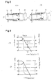
- FIG. 7 is an exploded perspective view of another embodiment of the objective lens driving apparatus in accordance with the invention.
- reference numeral 1 designates an objective lens, 20 a holder holding the objective lens, 21a a to 21b lengths of metallic wire for supporting the holder, 22a and 22b magnets, 23 a focussing driving coil wound on the holder 20, 24 a tracking driving coil constituted by four D-shaped coils fixed to the holder 20, 25 an integral yoke-base assembly formed by, for example, sintering from a magnetic material, 26 a wiring substrate, and 27 a holder for locating metallic wires 21a to 21b.
- the holder 27 is secured together with the substrate 26 to the yoke-base assembly 25 by means of a small screw 28.
- the formation of the yoke and base by the sintered metal permits a less-expensive mass-production of the parts with high dimensional stability.
- the yoke has a substantially U-shaped form, this is not exclusive and the yoke can have a form constituted by a combination of cylinders, as in the case of the yokes which are used in speakers.
- the yoke-base assembly which has been described as being a sintered body, may be formed by press work from a sheet metal.
Landscapes
- Physics & Mathematics (AREA)
- Optics & Photonics (AREA)
- Optical Recording Or Reproduction (AREA)
Claims (9)
Applications Claiming Priority (8)
| Application Number | Priority Date | Filing Date | Title |
|---|---|---|---|
| JP58097112A JPS59221839A (ja) | 1983-05-31 | 1983-05-31 | 光デイスクプレ−ヤの対物レンズ保持装置 |
| JP97121/83 | 1983-05-31 | ||
| JP58097111A JPS59221838A (ja) | 1983-05-31 | 1983-05-31 | 光デイスクプレ−ヤの対物レンズ駆動装置 |
| JP97111/83 | 1983-05-31 | ||
| JP97112/83 | 1983-05-31 | ||
| JP58097121A JPS59221840A (ja) | 1983-05-31 | 1983-05-31 | 光デイスクプレ−ヤの対物レンズ駆動装置 |
| JP117601/83 | 1983-06-28 | ||
| JP58117601A JPS6010430A (ja) | 1983-06-28 | 1983-06-28 | 対物レンズ駆動装置 |
Publications (3)
| Publication Number | Publication Date |
|---|---|
| EP0144445A1 EP0144445A1 (de) | 1985-06-19 |
| EP0144445A4 EP0144445A4 (de) | 1985-10-14 |
| EP0144445B1 true EP0144445B1 (de) | 1988-03-09 |
Family
ID=27468511
Family Applications (1)
| Application Number | Title | Priority Date | Filing Date |
|---|---|---|---|
| EP84902073A Expired EP0144445B1 (de) | 1983-05-31 | 1984-05-29 | Vorrichtung zum antreiben der objektivlinse eines optischen plattenspielers |
Country Status (4)
| Country | Link |
|---|---|
| US (2) | USRE37084E1 (de) |
| EP (1) | EP0144445B1 (de) |
| DE (1) | DE3469814D1 (de) |
| WO (1) | WO1984004841A1 (de) |
Families Citing this family (58)
| Publication number | Priority date | Publication date | Assignee | Title |
|---|---|---|---|---|
| JPS6095735A (ja) * | 1983-10-31 | 1985-05-29 | Hitachi Ltd | 対物レンズ駆動装置 |
| DE3574302D1 (en) * | 1984-10-02 | 1989-12-21 | Toshiba Kk | Optical head apparatus for recording and reproducing data on a recording medium |
| US4745589A (en) * | 1984-10-04 | 1988-05-17 | Seiko Epson Kabushiki Kaisha | Objective lens actuator having movements restricting control means for an optical head |
| JPH0668843B2 (ja) * | 1985-08-16 | 1994-08-31 | ソニー株式会社 | 光学ピツクアツプ装置 |
| US4813033A (en) * | 1985-10-30 | 1989-03-14 | International Business Machines Corporation | Two axis electromagnetic actuator with axis balanced suspension |
| US4750164A (en) * | 1985-12-09 | 1988-06-07 | Canon Kabushiki Kaisha | Optical system driving device |
| KR900006183B1 (ko) * | 1986-03-04 | 1990-08-25 | 상요 덴기 가부시기가이샤 | 광학식 픽업 장치 |
| US4845699A (en) * | 1986-03-04 | 1989-07-04 | Sanyo Electric Co., Ltd. | Electric mechanical transducer and optical type pickup apparatus driven by a magnetic field |
| US4782475A (en) * | 1986-12-22 | 1988-11-01 | Eastman Kodak Company | Flexure supported read head |
| NL8700148A (nl) * | 1987-01-21 | 1988-08-16 | Stichting Tech Wetenschapp | Inrichting voor het focusseren van electro-magnetische golven of geluid. |
| US4794581A (en) * | 1987-06-25 | 1988-12-27 | International Business Machines Corporation | Lens support system enabling focussing and tracking motions employing a unitary lens holder |
| JPS6442520U (de) * | 1987-09-08 | 1989-03-14 | ||
| JPH01113827U (de) * | 1988-01-21 | 1989-07-31 | ||
| JP2683243B2 (ja) * | 1988-03-29 | 1997-11-26 | オリンパス光学工業株式会社 | レンズの支持装置 |
| DE3828146A1 (de) * | 1988-08-19 | 1990-02-22 | Philips Patentverwaltung | Elektrodynamischer aktuator fuer eine optische einschreib- und ausleseeinheit |
| JP2537397B2 (ja) * | 1989-03-30 | 1996-09-25 | 旭光学工業株式会社 | 光学式ピックアップ装置 |
| JPH0690803B2 (ja) * | 1989-05-22 | 1994-11-14 | パイオニア株式会社 | 情報読取装置の製造方法 |
| KR920002933B1 (ko) * | 1989-05-25 | 1992-04-10 | 삼성전자 주식회사 | 광학적 정보기록 재생장치의 광 픽업구동장치 |
| US6141300A (en) * | 1989-06-20 | 2000-10-31 | Discovision Associates | Optical actuator including lens assembly with optical axis having symmetric suspensory forces acting thereon and optical disc system including same |
| US5265079A (en) | 1991-02-15 | 1993-11-23 | Applied Magnetics Corporation | Seek actuator for optical recording |
| US5136558A (en) * | 1989-06-20 | 1992-08-04 | Applied Magnetics Corporation | Two axis electromagnetic actuator |
| US5150343A (en) * | 1989-07-19 | 1992-09-22 | Matsushita Electric Industrial Co., Ltd. | Miniaturized low-power-consumption optical head provided with a state transformation mechanism |
| JP3048243B2 (ja) * | 1990-05-26 | 2000-06-05 | パイオニア株式会社 | 光ピックアップ |
| US5146441A (en) * | 1990-05-26 | 1992-09-08 | Pioneer Electronic Corporation | Supporting device of an optical pickup |
| US5218585A (en) * | 1990-10-01 | 1993-06-08 | International Business Machines Corporation | Phase shifting feedback control in an optical disk drive |
| US5313332A (en) * | 1990-11-16 | 1994-05-17 | Applied Magnetics Corporation | Flexure suspension for two axis actuator |
| US5729511A (en) * | 1991-02-15 | 1998-03-17 | Discovision Associates | Optical disc system having servo motor and servo error detection assembly operated relative to monitored quad sum signal |
| US5808980A (en) * | 1991-02-15 | 1998-09-15 | Discovision Associates | Seek actuator for optical recording |
| US5677899A (en) * | 1991-02-15 | 1997-10-14 | Discovision Associates | Method for moving carriage assembly from initial position to target position relative to storage medium |
| US6069857A (en) * | 1991-02-15 | 2000-05-30 | Discovision Associates | Optical disc system having improved circuitry for performing blank sector check on readable disc |
| US6236625B1 (en) | 1991-02-15 | 2001-05-22 | Discovision Associates | Optical disc system having current monitoring circuit with controller for laser driver and method for operating same |
| JP2978588B2 (ja) * | 1991-05-27 | 1999-11-15 | パイオニア株式会社 | 光ピックアップにおけるレンズ駆動装置の製造方法 |
| KR0160605B1 (ko) * | 1991-07-27 | 1999-01-15 | 강진구 | 광픽업의 대물렌즈 구동장치 |
| US5177640A (en) * | 1991-10-08 | 1993-01-05 | Applied Magnetics Corporation | Two-axis moving coil actuator |
| DE4134803A1 (de) * | 1991-10-22 | 1993-04-29 | Thomson Brandt Gmbh | Optische abtastvorrichtung mit einem linsenhalter |
| DE4135908A1 (de) * | 1991-10-31 | 1993-05-06 | Deutsche Thomson-Brandt Gmbh, 7730 Villingen-Schwenningen, De | Aktuatoranordnung |
| JPH05182227A (ja) * | 1991-12-27 | 1993-07-23 | Matsushita Electric Ind Co Ltd | 光ピックアップ |
| US5381288A (en) * | 1992-06-16 | 1995-01-10 | Applied Magnetics Corporation, Inc. | Center moment suspension assembly |
| TW239211B (en) * | 1993-04-02 | 1995-01-21 | Hyundai Electronics America | Electromagnetic lens actuator for optical disk drive |
| US5428589A (en) * | 1993-08-17 | 1995-06-27 | Eastman Kodak Company | Apparatus and method for an electromagnetic actuator with two orthogonal axes of motion |
| EP0643386A1 (de) * | 1993-09-14 | 1995-03-15 | Kabushiki Kaisha Toshiba | Objektivantriebsgerät und optisches Kopfantriebsgerät |
| US5715231A (en) * | 1993-09-14 | 1998-02-03 | Kabushiki Kaisha Toshiba | Objective lens driving apparatus and optical head driving apparatus |
| USRE40928E1 (en) | 1993-10-29 | 2009-10-06 | Tdk Corporation | Optical pickup |
| JP2833464B2 (ja) * | 1994-02-14 | 1998-12-09 | 日本電気株式会社 | 対物レンズアクチュエータおよびその製造方法 |
| KR100207626B1 (ko) * | 1994-04-30 | 1999-07-15 | 윤종용 | 렌즈구동장치 |
| US6434087B1 (en) | 1995-01-25 | 2002-08-13 | Discovision Associates | Optical disc system and method for controlling bias coil and light source to process information on a storage medium |
| US6091684A (en) * | 1995-01-25 | 2000-07-18 | Discovision Associates | Optical disc system and method for changing the rotational rate of an information storage medium |
| US5748578A (en) * | 1995-01-25 | 1998-05-05 | Discovision Associates | Colpitts type oscillator having reduced ringing and improved optical disc system utilizing same |
| US5920539A (en) * | 1995-01-25 | 1999-07-06 | Discovision Associates | Apparatus and method for suppression of electromagnetic emissions having a groove on an external surface for passing an electrical conductor |
| JP3480129B2 (ja) * | 1995-06-28 | 2003-12-15 | ソニー株式会社 | 二軸アクチェータ及び光学ピックアップ |
| JPH0991725A (ja) * | 1995-09-20 | 1997-04-04 | Matsushita Electric Ind Co Ltd | 光学式情報記録再生装置の光ピックアップ |
| DE19814777A1 (de) * | 1998-04-02 | 1999-10-07 | Thomson Brandt Gmbh | Optische Abtasteinrichtung mit verbesserter Ansprechcharakteristik |
| JP2000090455A (ja) * | 1998-09-08 | 2000-03-31 | Hitachi Ltd | 対物レンズ駆動装置及び光ディスク装置 |
| JP2001060328A (ja) * | 1999-08-24 | 2001-03-06 | Pioneer Electronic Corp | ディスクプレーヤのレンズ駆動装置 |
| US6785202B1 (en) * | 1999-08-30 | 2004-08-31 | Acute Applied Technologies, Inc. | Magnetic restoring device of an actuator |
| JP2004005813A (ja) * | 2002-05-31 | 2004-01-08 | Tdk Corp | 光ヘッド装置及びそれを用いた光再生装置 |
| TWI275086B (en) * | 2004-12-31 | 2007-03-01 | Ind Tech Res Inst | Object lens actuator |
| TWM329800U (en) * | 2007-08-16 | 2008-04-01 | Topray Technologies Inc | Fine focus driving device |
Citations (3)
| Publication number | Priority date | Publication date | Assignee | Title |
|---|---|---|---|---|
| JPS5771532A (en) * | 1980-10-22 | 1982-05-04 | Matsushita Electric Ind Co Ltd | Two axia driver |
| JPS5792441A (en) * | 1980-11-28 | 1982-06-09 | Hitachi Ltd | Three-dimensional driving body supporting device |
| JPS5865648U (ja) * | 1981-10-27 | 1983-05-04 | パイオニアビデオ株式会社 | 光学的情報読取装置の対物レンズ駆動装置 |
Family Cites Families (24)
| Publication number | Priority date | Publication date | Assignee | Title |
|---|---|---|---|---|
| JPS58102B2 (ja) | 1974-06-20 | 1983-01-05 | 萬世工業株式会社 | 光学的情報読み取り装置の自動焦点装置 |
| US4092529A (en) | 1975-10-08 | 1978-05-30 | Olympus Optical Company Limited | Detecting head for use in an apparatus for reading optically an information recorded on a record carrier as a track or tracks |
| JPS5625332A (en) | 1979-08-09 | 1981-03-11 | Japan Electronic Control Syst | Load drive circuit having overvoltage preventive circuit |
| JPS56130840A (en) * | 1980-03-17 | 1981-10-14 | Sanyo Electric Co Ltd | Pickup controlling mechanism for video disc recorder |
| JPS5718037A (en) | 1980-07-08 | 1982-01-29 | Matsushita Electric Ind Co Ltd | Driving device of object lens |
| JPS5737752A (en) | 1980-08-19 | 1982-03-02 | Matsushita Electric Ind Co Ltd | Optical scanner |
| US4592037A (en) * | 1980-11-28 | 1986-05-27 | Hitachi, Ltd. | Device for displacing a pickup head in multi-axial directions |
| JPS57103131A (en) * | 1980-12-18 | 1982-06-26 | Sony Corp | Biaxial driver |
| JPS57122030U (de) * | 1981-01-26 | 1982-07-29 | ||
| JPS57127934A (en) | 1981-01-30 | 1982-08-09 | Hitachi Ltd | Supporter for electromechanical converter |
| JPS6026750B2 (ja) | 1981-04-01 | 1985-06-25 | 日産自動車株式会社 | ル−フのドリツプモ−ル取付構造 |
| JPS57178233A (en) * | 1981-04-27 | 1982-11-02 | Sony Corp | Supporting structure of optical system |
| JPS57183640A (en) | 1981-05-08 | 1982-11-12 | Sanyo Electric Co Ltd | Pickup device |
| JPS57189141A (en) | 1981-05-19 | 1982-11-20 | Canon Inc | Manufacture of photoconductive layer |
| JPS57198550A (en) * | 1981-05-29 | 1982-12-06 | Sony Corp | Supporting device for optical system |
| JPS57198551A (en) * | 1981-07-09 | 1982-12-06 | Sony Corp | Supporting device for optical system |
| JPS5826713U (ja) * | 1981-08-14 | 1983-02-21 | ヤマハ株式会社 | ピツクアツプカ−トリツジの振動系 |
| JPS5848033U (ja) * | 1981-09-22 | 1983-03-31 | 萬世工業株式会社 | レンズ駆動装置 |
| JPS5864648A (ja) | 1981-10-13 | 1983-04-18 | Matsushita Electric Ind Co Ltd | 対物レンズ駆動装置 |
| JPS58146035A (ja) | 1982-02-23 | 1983-08-31 | Foster Denki Kk | 情報再生装置 |
| US4553227A (en) * | 1982-04-23 | 1985-11-12 | Tokyo Shibaura Denki Kabushiki Kaisha | Optical pickup |
| US4568142A (en) * | 1982-04-26 | 1986-02-04 | Hitachi, Ltd. | Objective lens drive apparatus |
| US4475179A (en) * | 1982-06-30 | 1984-10-02 | Eastman Kodak Company | Optical disc write/read methods and apparatus with improved focus and tracking control |
| US4504935A (en) * | 1983-02-14 | 1985-03-12 | U.S. Philips Corporation | Electrodynamic focus and radial slide drive for an optical disc system |
-
1984
- 1984-05-29 US US09/120,799 patent/USRE37084E1/en not_active Expired - Lifetime
- 1984-05-29 DE DE8484902073T patent/DE3469814D1/de not_active Expired
- 1984-05-29 EP EP84902073A patent/EP0144445B1/de not_active Expired
- 1984-05-29 WO PCT/JP1984/000275 patent/WO1984004841A1/ja not_active Ceased
- 1984-05-29 US US06/700,818 patent/US4646283A/en not_active Ceased
Patent Citations (3)
| Publication number | Priority date | Publication date | Assignee | Title |
|---|---|---|---|---|
| JPS5771532A (en) * | 1980-10-22 | 1982-05-04 | Matsushita Electric Ind Co Ltd | Two axia driver |
| JPS5792441A (en) * | 1980-11-28 | 1982-06-09 | Hitachi Ltd | Three-dimensional driving body supporting device |
| JPS5865648U (ja) * | 1981-10-27 | 1983-05-04 | パイオニアビデオ株式会社 | 光学的情報読取装置の対物レンズ駆動装置 |
Also Published As
| Publication number | Publication date |
|---|---|
| WO1984004841A1 (en) | 1984-12-06 |
| EP0144445A4 (de) | 1985-10-14 |
| DE3469814D1 (en) | 1988-04-14 |
| US4646283A (en) | 1987-02-24 |
| EP0144445A1 (de) | 1985-06-19 |
| USRE37084E1 (en) | 2001-03-06 |
Similar Documents
| Publication | Publication Date | Title |
|---|---|---|
| US4646283A (en) | Objective lens driving apparatus for optical disc player | |
| US5208703A (en) | Apparatus for supporting optical system | |
| US4669823A (en) | Optical system drive for optical recording/reproducing apparatus | |
| US7028318B2 (en) | Optical head with lens holder supported by suspension wires at central and end portions | |
| KR100338169B1 (ko) | 대물렌즈구동장치및코일보빈 | |
| US6574052B2 (en) | Optical pick-up actuator | |
| JP2765633B2 (ja) | 光学系支持装置 | |
| US6493158B2 (en) | Lens driving apparatus for optical disc player and printed circuit board coils for lens driving apparatus for disc player | |
| US6018509A (en) | Connector apparatus for electrically connecting an optical component drive device to an external electrical circuit | |
| KR930011446B1 (ko) | 트랜스듀우서 구동장치 | |
| US6714364B2 (en) | Optical pick-up actuator | |
| EP1551013B1 (de) | Positionierungsanordnung für einen optischen Abtastkopf | |
| US7567486B2 (en) | Slim type optical pick-up actuator | |
| JP2856078B2 (ja) | 対物レンズアクチュエータ | |
| KR100510538B1 (ko) | 광픽업 액추에이터 | |
| JP3567310B2 (ja) | 光ヘッド装置 | |
| EP0621587A1 (de) | Vorrichtung zum antrieb eines optischen teiles | |
| JPH07226056A (ja) | ヘッド装置及びその支持基板 | |
| KR100630775B1 (ko) | 광픽업용 다중배선 서스펜션 및 상기 다중배선 서스펜션이장착된 광픽업용 액츄에이터 | |
| KR100497728B1 (ko) | 광픽업 구동기 | |
| JP2716749B2 (ja) | 光学系支持装置 | |
| EP1914763B1 (de) | Leiterplatte mit gedruckten Wicklungen | |
| JP2541963B2 (ja) | 対物レンズ駆動装置 | |
| EP2128862A1 (de) | Flachauslöser aus einem PCB-Teil | |
| JPH08315388A (ja) | 光ディスク装置の対物レンズ駆動装置 |
Legal Events
| Date | Code | Title | Description |
|---|---|---|---|
| PUAI | Public reference made under article 153(3) epc to a published international application that has entered the european phase |
Free format text: ORIGINAL CODE: 0009012 |
|
| 17P | Request for examination filed |
Effective date: 19850206 |
|
| AK | Designated contracting states |
Designated state(s): DE FR GB |
|
| 17Q | First examination report despatched |
Effective date: 19861015 |
|
| GRAA | (expected) grant |
Free format text: ORIGINAL CODE: 0009210 |
|
| AK | Designated contracting states |
Kind code of ref document: B1 Designated state(s): DE FR GB |
|
| REF | Corresponds to: |
Ref document number: 3469814 Country of ref document: DE Date of ref document: 19880414 |
|
| ET | Fr: translation filed | ||
| PLBE | No opposition filed within time limit |
Free format text: ORIGINAL CODE: 0009261 |
|
| STAA | Information on the status of an ep patent application or granted ep patent |
Free format text: STATUS: NO OPPOSITION FILED WITHIN TIME LIMIT |
|
| 26N | No opposition filed | ||
| REG | Reference to a national code |
Ref country code: GB Ref legal event code: 746 Effective date: 19970901 |
|
| REG | Reference to a national code |
Ref country code: GB Ref legal event code: IF02 |
|
| PGFP | Annual fee paid to national office [announced via postgrant information from national office to epo] |
Ref country code: FR Payment date: 20030508 Year of fee payment: 20 |
|
| PGFP | Annual fee paid to national office [announced via postgrant information from national office to epo] |
Ref country code: GB Payment date: 20030528 Year of fee payment: 20 |
|
| PGFP | Annual fee paid to national office [announced via postgrant information from national office to epo] |
Ref country code: DE Payment date: 20030605 Year of fee payment: 20 |
|
| PG25 | Lapsed in a contracting state [announced via postgrant information from national office to epo] |
Ref country code: GB Free format text: LAPSE BECAUSE OF EXPIRATION OF PROTECTION Effective date: 20040528 |
|
| REG | Reference to a national code |
Ref country code: GB Ref legal event code: PE20 |