EP0144505A2 - Dispositif pour réaliser des étiquettes - Google Patents
Dispositif pour réaliser des étiquettes Download PDFInfo
- Publication number
- EP0144505A2 EP0144505A2 EP84107622A EP84107622A EP0144505A2 EP 0144505 A2 EP0144505 A2 EP 0144505A2 EP 84107622 A EP84107622 A EP 84107622A EP 84107622 A EP84107622 A EP 84107622A EP 0144505 A2 EP0144505 A2 EP 0144505A2
- Authority
- EP
- European Patent Office
- Prior art keywords
- base
- tape material
- spool
- overlay
- mounting
- Prior art date
- Legal status (The legal status is an assumption and is not a legal conclusion. Google has not performed a legal analysis and makes no representation as to the accuracy of the status listed.)
- Granted
Links
- 239000000463 material Substances 0.000 claims abstract description 262
- 230000007246 mechanism Effects 0.000 claims abstract description 56
- 239000000853 adhesive Substances 0.000 claims abstract description 21
- 230000001070 adhesive effect Effects 0.000 claims abstract description 21
- 238000005096 rolling process Methods 0.000 claims abstract description 17
- 238000003825 pressing Methods 0.000 claims abstract description 5
- 230000006835 compression Effects 0.000 claims description 5
- 238000007906 compression Methods 0.000 claims description 5
- 238000010030 laminating Methods 0.000 claims description 5
- 230000004048 modification Effects 0.000 abstract description 8
- 238000012986 modification Methods 0.000 abstract description 8
- 101100478228 Danio rerio spopla gene Proteins 0.000 abstract 1
- 101100043258 Mus musculus Spopl gene Proteins 0.000 abstract 1
- 101100043259 Xenopus laevis spopl gene Proteins 0.000 abstract 1
- 238000010276 construction Methods 0.000 description 14
- 238000003475 lamination Methods 0.000 description 12
- 238000007639 printing Methods 0.000 description 6
- 244000043261 Hevea brasiliensis Species 0.000 description 4
- 239000011248 coating agent Substances 0.000 description 4
- 238000000576 coating method Methods 0.000 description 4
- 239000002184 metal Substances 0.000 description 4
- 229920003052 natural elastomer Polymers 0.000 description 4
- 229920001194 natural rubber Polymers 0.000 description 4
- 238000012840 feeding operation Methods 0.000 description 3
- 239000004593 Epoxy Substances 0.000 description 2
- 238000003780 insertion Methods 0.000 description 2
- 230000037431 insertion Effects 0.000 description 2
- 238000009434 installation Methods 0.000 description 2
- 230000002452 interceptive effect Effects 0.000 description 2
- 230000001788 irregular Effects 0.000 description 2
- 238000012545 processing Methods 0.000 description 2
- 230000001681 protective effect Effects 0.000 description 2
- 239000012780 transparent material Substances 0.000 description 2
- 229910000831 Steel Inorganic materials 0.000 description 1
- 238000009825 accumulation Methods 0.000 description 1
- 230000006978 adaptation Effects 0.000 description 1
- 230000000712 assembly Effects 0.000 description 1
- 238000000429 assembly Methods 0.000 description 1
- 238000005520 cutting process Methods 0.000 description 1
- 238000013461 design Methods 0.000 description 1
- 238000005516 engineering process Methods 0.000 description 1
- 238000002372 labelling Methods 0.000 description 1
- 238000003754 machining Methods 0.000 description 1
- 238000004519 manufacturing process Methods 0.000 description 1
- 238000000034 method Methods 0.000 description 1
- 239000004033 plastic Substances 0.000 description 1
- 238000003892 spreading Methods 0.000 description 1
- 230000007480 spreading Effects 0.000 description 1
- 239000010959 steel Substances 0.000 description 1
Images


Classifications
-
- B—PERFORMING OPERATIONS; TRANSPORTING
- B41—PRINTING; LINING MACHINES; TYPEWRITERS; STAMPS
- B41J—TYPEWRITERS; SELECTIVE PRINTING MECHANISMS, i.e. MECHANISMS PRINTING OTHERWISE THAN FROM A FORME; CORRECTION OF TYPOGRAPHICAL ERRORS
- B41J15/00—Devices or arrangements of selective printing mechanisms, e.g. ink-jet printers or thermal printers, specially adapted for supporting or handling copy material in continuous form, e.g. webs
- B41J15/04—Supporting, feeding, or guiding devices; Mountings for web rolls or spindles
- B41J15/06—Supporting, feeding, or guiding devices; Mountings for web rolls or spindles characterised by being applied to printers having stationary carriages
-
- B—PERFORMING OPERATIONS; TRANSPORTING
- B31—MAKING ARTICLES OF PAPER, CARDBOARD OR MATERIAL WORKED IN A MANNER ANALOGOUS TO PAPER; WORKING PAPER, CARDBOARD OR MATERIAL WORKED IN A MANNER ANALOGOUS TO PAPER
- B31D—MAKING ARTICLES OF PAPER, CARDBOARD OR MATERIAL WORKED IN A MANNER ANALOGOUS TO PAPER, NOT PROVIDED FOR IN SUBCLASSES B31B OR B31C
- B31D1/00—Multiple-step processes for making flat articles ; Making flat articles
- B31D1/02—Multiple-step processes for making flat articles ; Making flat articles the articles being labels or tags
-
- B—PERFORMING OPERATIONS; TRANSPORTING
- B65—CONVEYING; PACKING; STORING; HANDLING THIN OR FILAMENTARY MATERIAL
- B65H—HANDLING THIN OR FILAMENTARY MATERIAL, e.g. SHEETS, WEBS, CABLES
- B65H39/00—Associating, collating, or gathering articles or webs
- B65H39/16—Associating two or more webs
-
- Y—GENERAL TAGGING OF NEW TECHNOLOGICAL DEVELOPMENTS; GENERAL TAGGING OF CROSS-SECTIONAL TECHNOLOGIES SPANNING OVER SEVERAL SECTIONS OF THE IPC; TECHNICAL SUBJECTS COVERED BY FORMER USPC CROSS-REFERENCE ART COLLECTIONS [XRACs] AND DIGESTS
- Y10—TECHNICAL SUBJECTS COVERED BY FORMER USPC
- Y10T—TECHNICAL SUBJECTS COVERED BY FORMER US CLASSIFICATION
- Y10T156/00—Adhesive bonding and miscellaneous chemical manufacture
- Y10T156/17—Surface bonding means and/or assemblymeans with work feeding or handling means
- Y10T156/1702—For plural parts or plural areas of single part
- Y10T156/1712—Indefinite or running length work
- Y10T156/1741—Progressive continuous bonding press [e.g., roll couples]
Definitions
- This invention relates to an apparatus for producing labels, and, more particularly, t Q an apparatus having a friction-feed and surface-driven roller mechanism for producing the laminated labels that is readily mounted to and adapted for use with different types of typewriters and printers.
- Laminated labels with printed indicia protected by a transparent cover have proven effective for various applications, e.g., the labeling of property such as library books and the like.
- Laminated labels and apparatus for producing such laminated labels for use with a typewriter having a rolling platen are described in U.S. Patent No. 3,295,654 issued to Clinton et al. and assigned to American- Library Association ("ALA").
- the laminated labels are formed from a strip of a base-tape material and a strip of overlay-tape material.
- the base-tape material has an adhesive coating on one surface with a protective backing strip in opposite relationship with the adhesive coating.
- the strip of overlay-tape material is transparent and has an adhesive coating on one surface.
- the known method of producing such laminated labels comprises the steps of printing the desired material on the surface of the strip of base material, placing the strip of transparent material onto the strip of base material with the adhesive coating adjacent the printed indicia, cutting the label from the combined strips of base material and transparent material, and removing the protective backing strip of the base material.
- the conventional label-producing apparatus is provided with a holder for rotatably supporting the spool of base-tape material and a holder for rotatably supporting the spool of overlay-tape material.
- the overlay-tape and base-tape spool holders are mounted between two similarly-shaped and parallely- arranged retainer plates.
- one of the retainer plates is spring-loaded in the center thereof with the spring-load distributed or exerted against both the overlay-tape spool and the base-tape spool rotatably mounted between the two retainer ; plates.
- This mechanism provides tension on both spools as the base-tape and overlay-tape materials are supplied to the platen/gear-driven feed roller mechanism.
- wax or paper discs are provided on opposite sides of the base-tape spool and overlay-tape spool to keep the retainer plates clean from adhesive of the tapes.
- the conventional label-producing apparatus is usable only on a basic typewriter having a rolling platen and requires a specially-made platen for installation to the particular typewriter.
- this conventional label-producing apparatus requires permanent modification and assembly to the typewriter.
- the conventional label-producing apparatus is not adaptable to all types of typewriters with rolling platens.
- many typewriters have small platens and thus providing gears on the platens is difficult.
- this conventional label-producing apparatus is not adaptable to printers with fixed or non-roller type platens, such as automated data terminal and computer printers using tractor mechanisms.
- the conventional apparatus is not suitable for automated processing of laminated labels for a significant commercial market now existing because of the advances in computer and printer technology. !
- the conventional label-producing apparatus suffers from certain disadvantages in performance in that there are both material misalignments and air pockets developed between the overlay-tape and base tape during lamination because of irregula feed through the roller assembly and/or irregularities in the surfaces of the platen or rollers.
- the conventional label-producing apparatus has certain disadvantages in performance in that there is difficulty in alignment of the overlay-tape and base-tape materials between the rollers in the initial feeding stage.
- the conventional label-producing apparatus suffers in performance and reliability in operation due to excessive drag on the overlay-tape and base-tape spools, wherein the accumulation of the spool drag and the drag inherent in the gear interchange between the platen and feed roller exceeds the drive capabilities of many electronic typewriters and small data printers.
- the conventional label-producing apparatus requires from the standpoint of marketing and service requirements a large number of different components and multiple platens to accommodate the many different brands of typewriters.
- the conventional label-producing apparatus suffers from a lack of reliable operation, a lack of quality
- an improved label-producing apparatus device which is more reliable in operation, provides a higher quality lamination, is relatively simple in structure, is versatile and adaptable for use in many different types of typewriters and printers, and is easy to assemble and disassemble from the typewriter or printer.
- Yet another object-of_the invention is to provide a label-producing apparatus which is adaptable for use with data terminal and computer printers to allow automated processing capabilities for producing laminated labels.
- Another object of the present invention is to provide a label-producing apparatus which provides easy and quick assembly and disassembly from the typewriter or printer with which the apparatus is to be used.
- Yet another object of the invention is to provide a label-producing apparatus which has minimum mechanical drag to improve feed life for the typewriter or printer.
- Yet another object of the present invention is to provide a label-producing apparatus having an improved base-tape material spool supply mechanism with independent and precise tension adjustment and tracking controls.
- Another object of this invention is to provide a label-producing apparatus which has an improved base-tape and overlay-tape material supply mechanism having minimum hardware and easy adjustment controls for changes in the width of the base-tape and overlay-tape materials.
- an apparatus for producing laminated labels used in combination with a typewriter or printer, comprising: (1) means for rotatably mounting a spool of transparent overlay-tape material having an adhesive surface; (2) means for rotatably mounting a spool of base-tape material having a printable surface and an opposite protected adhesive surface, the base-tape material mounting means including means for adjustably applying tension against the base-tape material spool independent of the overlay-tape material spool; (3) friction-feed, pressure-loaded roller means associated with the print head of the typewriter or printer for pulling the overlay-tape and base-tape materials into and through the roller means and pressing the adhesive surface of the overlay-tape material into intimate contact with the printable surface of the base-tape material, the friction and pressure-load of the roller means being operably adjustable; and (4) means for mounting the roller means adjacent the print head of the typewriter or printer.
- a first embodiment of the apparatus is adapted for use with typewriters or printers having a rolling platen; a second embodiment is adapted for use with printers having a fixed platen and sheet-feed tractor mechanism; and a third embodiment is adapted for use with typewriters having a moving, rolling platen.
- the means for rotatably mounting the base-tape material spool comprises a first mounting assembly either removably connected to the housing of the typewriter or printer or mounted externally from the typewriter or printer.
- the means for rotatably mounting the overlay-tape material spool and the means for mounting the roller means comprises a second assembly for mounting both the overlay-tape material spool and a frictionally surface-driven feed roller of the roller means which is pivotally connected to the first mounting assembly.
- a weight mechanism is connected to the second mounting assembly for providing a force through the feed roller against the typewriter platen as a result of the moment caused by the weight and distance of the weight to the pivotal connection of the second mounting assembly to the first mounting assembly.
- the weight mechanism is adjustable to vary the moment force of the feed roller against the platen.
- the means for mounting the roller means and means for mounting the overlay-tape material spool comprises a first assembly for mounting both the overlay-tape material spool and roller means having a frictionally surface-driven feed roller and drive roller which is attachable to the tractor mechanism drive shaft.
- This first assembly is detachably mounted to the idle and drive shafts of the sheet-feeding tractor mechanism of the printer.
- the means for rotatably mounting the base-material spool comprises a second assembly for separately and detachably rotatably mounting the i base-tape material spool to the inside of the printer housing and for supplying the base-tape material past the fixed platen of the printer.
- a spring means acts against the frictionally surface-driven feed roller for adjustably applying the friction-force and pressure-load of the feed roller against the drive roller.
- the means for rotatably mounting the base-tape material spool, the means for rotatably mounting the overlay-tape material spool, and the means for mounting a frictionally surface-driven feed roller of the roller means comprises a mounting assembly removably connected to the platen and carriage of the typewriter.
- the mounting assembly comprises a subassembly for rotatably mounting the overlay-tape material and the base-tape material spools having a support plate bracket, an outside plate retainer bracket which is removably positioned parallel to the support plate bracket, and spindles mounted to the support bracket and extending through the outside plate retainer bracket for rotatably mounting the overlay tape material spool and the base-tape material spool between the support plate bracket and the oufside plate retainer brackec.
- the outside plate retainer bracket has stand-off legs extending from the retainer bracket for engaging the support bracket.
- deformable drag discs attached on opposite sides of the base-tape material spool and adjustable locating and tensioning screw means attached to the base-tape material spool mounting assembly for laterally positioning the base-tape material spool on the spindle and for contacting the deformable drag discs to apply tension against the base-tape material spool independent of the overlay-tape material spool in accordance with the required operational feeding and tracking controls of the base-tape material to the roller means.
- the drag discs are fixedly inserted into the base-tape material spool.
- the drag discs are formed as an integral part of the spool for the base-tape material.
- the drag of the base-tape material is caused by the compression or deformation of the disc as the rotating disc runs over the adjustable tensioning screw means.
- FIGS. 1-4 there are described hereinafter three preferred embodiments of an apparatus for producing laminated labels used in combination with a typewriter or printer.
- The-first preferred embodiment of the label-producing apparatus described hereinafter is adapted for use with a typewriter or printer having a rolling platen, shown in FIGS. 1-4 and generally identified with reference numeral 20.
- the second embodiment of the label-producing apparatus described hereinafter is adapted for use with a printer having a fixed platen and sheet-feeding tractor mechanism, is shown in FIGS. 9-12 of the drawings, and is generally identified with reference numeral 100.
- the third embodiment of the label-producing ! apparatus described herein is adapted for use with a typewriter having a moving, rolling platen, is shown in FIGS. 13-15, and is generally identified as reference numeral 200.
- the apparatus in accordance with the invention includes (1) means for rotatably mounting a spool 15 of transparent overlay-tape material 16 having an adhesive surface; (2) means for rotatably mounting a spool 17 of base-tape material 18 having a printable surface and opposite protected adhesive surface, the base-tape Material mounting means including means for adjustably applying tension against the base-tape material spool'17 independent of the overlay-tape material spool 15; (3.) friction-feed, pressure-loaded roller means associated with the print heads of the typewriter or print head of the printer for pulling the overlay- tape and base-tape materials 16 and 18 into and through the roller means and pressing the adhesive surface of the overlay-tape material 16 into intimate contact with the printable surface of the base-tape material 18, the friction-force and pressure-load of the roller means being operably adjustable, and (4) means for mounting the roller means adjacent the print heads of the typewriter or print head of the printer.
- the roller means comprises a frictionally surface-driven, pressure-loaded roller acting against a drive roller which is either a separate drive roller or the platen of a typewriter or printer.
- the means for adjustably applying tension against the base-tape material spool 17 comprises deformable drag discs fixed on opposite sides of the base-material spool and adjustable locating and tensioning screw means attached to the base-tape material spool mounting assembly for laterally aligning the base-tape material spool and for contacting the deformable drag disc to apply tension against the base-tape material spool, independent of the overlay-tape material spool and in accordance with the required operational feeding and tracking controls of the base-tape material to the roller means.
- the first embodiment of the label-producing apparatus 20 is adapted for use with a typewriter or printer having a rolling platen, such as typewriter 22 with conventional platen 24.
- the means for rotatably mounting the base-tape material spool comprises a first mounting assembly 26 which is either removably connected to the housing of the typewriter or printer, or mounted externally away from the typewriter or printer.
- the first mounting assembly 26 includes a mounting mechanism which is a mounting stand 28 to which the base-tape material spool mounting assembly 26 is attached.
- the mounting stand 28 is located on the table on which the typewriter or printer is positioned in a manner for providing rigid support to the assembly 26.
- the stand 28 contains vertical, horizontal and angular adjustability for proper location of the assembly 26 over the upper portion of the typewriter housing, as illustrated in FIG. 1.
- the mounting mechanism is a mounting block 30 for attaching the assembly 26 to the rear portion of the typewriter or printer housing by epoxy, double-faced tape or the like.
- the mounting block 30 has a corresponding dovetail mounting arrangement between the block and assembly and an adjustable slot and screw arrangement between the block and assembly for connecting the two components and adjusting the location of the assembly to the typewriter platen 24.
- the block 30 should be mounted on the typewriter at an appropriate location which will not interfere with normal typewriter or printer paper operation. Different mounting blocks 30, moreover, can be used to accomodate different brands of typewriters and printers.
- the base-tape mounting assembly 26 should be located as illustrated in FIGS. 1 and 2 where the assembly 26 is adjacent the platen 24 of the
- the mounting assembly 26 further comprises a base support member 32 having the configuration shown in FIGS. 1, 2 and 4.
- Vertical supports 34 and 36 are attached to the rear portion of the base support member 32 extending upwardly for rotatably-mounting the base-material spool 17.
- a spindle 38 is provided between the vertical support arms 34 and 36 and mounted to the vertical support arms 34 and 36 at the ends thereof through holes 40 and 42 formed in the respective vertical supports as shown in FIG. 4.
- the spool 17 of the base-tape material is rotatably mounted on the spindle 38, as depicted in FIGS. 1 and 2.
- the base support member 32 has a pair of L-shaped arms-44 and 46 extending from the front portion thereof toward the platen 24 of the typewriter. At the ends of the L-shaped arms 44 and 46 facing the typewriter platen 24, there are formed therein through holes 48 for receiving pivoting pins 50 and thus pivotally attaching a second mounting assembly of the apparatus as will be described hereinafter.
- a plurality of pivoting holes 48 are provided preferably to allow different pivotal mounting locations of the second mounting assembly to the first mounting assembly of the apparatus for fitting different types of typewriters and printers.
- the length of the base support member 32 is such that the L-shaped arms 44 and 46 would be positioned adjacent the platen 24 of the typewriter printer, with the angle of the L-shaped arms 44 and 46 to the member 32 being approximately 120°.
- the location of the assembly 26 can be adjusted by the detachable mounting of the base support member 32 to the mounting stand 28 or mounting block 30 as described earlier.
- the means for rotatably mounting the overlay-tape material spool and the means for mounting the roller means comprises a second mounting assembly 52 for mounting both the overlay-tape material spool 15 and the frictionally surface-driven feed roller of the roller means.
- This second mounting assembly 52 is pivotally connected to the first mounting assembly 26 and has a configuration and structure as best seen in FIGS. 1, 2, 3 and 4.
- the second mounting assembly 52 has a U-shaped frame support member 54 having side sections 56 and 58 and a front section 60. Between the side sections 56 and 58.of the U-shaped member 54, there is rotatably mounted the overlay- i tape material spool 15. That is, a spindle 62 is mounted at each end thereof through holes 62 formed in the central area of the respective side sections 56 and 58. The overlay-tape material spool 15 is then rotatably mounted on the spindle 62 for feeding of the overlay-tape material 16 toward the platen 24 of the typewriter as shown by arrow B in FIG. 2.
- the drive roller of roller means comprises the conventional platen 24 of the typewriter or printer.
- the frictionally surface-driven pressure-loaded roller of the roller means comprises a frictionally, surface-driven feed roller 66 which is rotatably mounted at the lower end of the U-shaped support member 54 between the side sections 56 and 58 as best illustrated in FIGS. 1 and 2 for engaging the platen 24.
- the feed roller preferably has an approximately one-inch cross-sectional diameter and comprises an inner metal shaft and an outer surface of a natural rubber of approximately 50 durometers.
- the shaft ends of the feed roller 66 are rotatably mounted in holes 67 and 68 formed at the lower ends of the respective side sections 56 and 58 of the U-shaped support member 54 using bearings or the like.
- the second mounting assembly 52 has a pair of short legs 70 and 72 extending from the lower rear area of the side sections 56 and 58 of the bracket 54.
- the legs 70 and 72 have one or more through holes 74 formed thereon that are compatable with the holes 48 formed in the L-shaped arms 44 and 46 of the first mounting assembly 26.
- the short legs 70 and 72 are positioned inwardly of the L-shaped arms 44 and 46 such that the second mounting assembly 52 is pivotally mounted to the first mounting assembly 26 by placing the pivoting pins 50 through the corresponding holes 48 of the first mounting assembly and the holes 74 of the second mounting assembly.
- the second mounting assembly 52 with the feed roller 66 and overlay-tape material spool 15 can be moved away from the platen 24 of the typewriter for initial alignment and feeding of the overlay-tape and base-tape materials 16 and 18 as will be described hereinafter.
- the feed roller 66 and the platen 24 of the typewriter pull the overlay-tape material 16 and the base-tape material 18 into and between the feeder roller 66 a:ad the platen 24 of the typewriter and press the adhesive surface of the overlay-tape material into intimate contact with the printable surface of the base-tape material to form a laminated label strip feed outwardly as best seen in FIG. 2 and indicated by arrow C.
- the first embodiment of the label-producing apparatus further includes a weight mechanism 76 connected to the second mounting assembly 52 for providing a force of the feed roller 66 against the platen 24.
- a weight mechanism 76 is adjustable to vary the moment force of the feed roller against the platen.
- the weight mechanism 76 comprises a threaded rod 78 which is threadedly attached through a threaded hole formed in the front section 60 of the U-shaped support member 54 of the second mounting assembly 52.
- a weight 80 is either fixed to the threaded rod 78 or threaded to the end of the rod 78 in such a manner as to allow different weights to be attached to the rod 78.
- the distance between the weight 80 and the pivoting point of the second mounting assembly 52 to the first mounting assembly thus can be adjusted to vary the moment force MF being applied through the feed roll 66 against the platen 24 of the typewriter.
- the label-producing apparatus in accordance with the invention further includes means for adjustably applying tension against the base-tape material spool 17 independent of the overlay-tape material spool 15. This is a significant component of the label-producing apparatus in order to allow the precise feeding of the materials through the roller assembly.
- the label-producing apparatus can be utilized on many different types of typewriters or printers, particularly electronic typewriters and small printers which have low drive capabilities and require optimum feeding control and tracking requirements to properly perform the lamination operation.
- the means for adjustably applying tension against the base-tape,material spool in apparatus 20 comprises deformable drag discs 82 fixed on opposite ends of the base-material spool 17.
- the drag discs 82 there is provided the drag disc 82A formed of a deformable plastic which is fixedly insertable into the end of the base-tape material spool 17 as illustrated in FIGS. 5 and 6.
- the drag disc 82A has a sidewall 84 and a circular cap 86 projecting from the sidewall 84 which is insertable into the end of the base-material spool 17.
- locking tabs 88 are formed on the outer circumference of the cap 84 for engaging the inner surface of the base-tape material spool 17 and thus fixedly securing the disc 82A to the end of the spool 17.
- Adhesive may be provided on the locating tabs 86 for bonding the inner surface of the base-material spool and thus ensure that the drag disc 82A is fixedly secured to the base-tape material spool 17.
- the side wall 84 of the disc 82A extends slightly laterally outwardly from the center portion near the cap 84 to the outer circumferencial portion of the disc to allow for deformation without interfering with the unwinding of the base-tape material 18 from the spool 17.
- the side walls 84 also limit lateral material movement and adhesive flow outside the disc.
- the angle of the outwardly extending sidewall of the disc is approximately 5° - 10°.
- FIGS. 7 and 8 An alternative embodiment for the drag disc 82 is illustrated in FIGS. 7 and 8 as disc 82B.
- the drag disc 82B is formed as an integral part of the the bass ⁇ tape material spool 17, thus eliminating the need for the projecting cap and locking tabs, and the insertion step of the disc into the base-tape material spool.
- the drag disc 82B would have the same angled side wall 84 as described with respect to the disc 82A embodiment shown in FIGS. 5-6 to allow proper unwinding of the base-tape material 18.
- the means for adjusttably applying tension against the base-tape material spool 17 further comprises adjustable locating and tensioning screw means attached to the mounting assembly.26 for laterally aligning the spool 17 and for contacting the deformable drag disc 82 to apply tension against the base-tape material spool 17 independent of the overlay-tape spool 15.
- the adjustable locating and tensioning screw means includes a pair of screws 90 and 92 threadably mounted through respective holes formed in the vertical supports 34 and 36 of the first mounting assembly 26, as best seen in FIGS. 1-2 and 4.
- the screws 90 and 92 are adjustable against the side walls 84 of the corresponding deformable drag discs 82 for applying a tension against the base-tape material spool 17 in accordance with the required operational feeding and tracking controls of the base-tape material 18 to the feed roller 66 and platen 24.
- the screws 90 and 92 are mounted on the vertical supports 34 and 36 for contacting the side walls 84 of the drag discs 82 at the outer circumference area thereof and to deform the drag disc 82 in the manner illustrated in FIGS. 5 and 7.
- the angle of the side wall 84 from the spool 17 allows for deformation of the drag disc without interfering with the unwinding of the base-tape material.
- screws 94 and 96 are threadably mounted in through holes formed on the side sections 56 and 58 of the U-shaped support member 54 as illustrated in FIGS. 1, 3 and 4.
- This allows for independent alignment of the overlay-tape material spool 15 in relationship to the independent alignment and tensioning of the base-tape material spool 17.
- the above type of construction eliminates or reduces unnecessary drag against the overlay-tape material since drag is already provided by the adhesive surface of the clear-tape material during operation. This construction also provides for fine drag tuning of the base-tape material to further reduce any unnecessary drag on the base-tape spool 17.
- the overall construction of the first embodiment of the invention achieves a label-producing apparatus.20 which is more reliable in operation, provides a higher quality lamination, is relatively simple in construction, is versatile and adapted for use in many different types of typewriters and pointers and is easy to assemble and disassemble from the typewriter or printer.
- This label-producing apparatus 20 requires no permanent modification to the typewriter or printer and allows it to be used with typewriters and small data printers which have low drive capabilities not heretofore achieved.
- the apparatus 20 requires only an open space in the typewriter or printer platen area and clearance for the second pivoting assembly 52.
- the apparatus 20 can be mounted using a simple block 30 either to the typewriter or printer, or can be mounted externally from the typewriter or printer using a stand 28.
- the apparatus when not being used, simply can be removed from the typewriter or printer to allow full width use of the normal paper capabilities of the typewriter or printer.
- This apparatus also eliminates the need for special part stocking, machining and other factory adjustment or handling of the specific typewriters or printers of the customer.
- the initial alignment and feeding operations for placing the overlay-tape material and base-tape material together for subsequent feeding and laminating of the labels is expedited and improved.
- Use of the frictionally surface-driven, pressure-loaded roller 66 also improves the laminating operation being performed. More specifically, the roller 66 eliminates both material misalignments and air pockets developed between the overlay-tape and base-tape materials during lamination because of irregular feed through the roller assembly and irregularities in the surface of the conventional typewriter platen. Eliminating the air pockets also prevents ink from spreading on the base-tape material immediately after the printing thereon by the print heads of the typewriter.
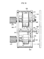
- the second preferred embodiment of the label-producing apparatus 100 is adapted for use with a printer having a fixed platen 102, a print head 104 associated therewith, and a sheet-feeding tractor mechanism 106, such as that used in printing of continuous forms in computer printers or data terminal printers.
- the sheet-feeding tractor mechanism 106 includes a drive shaft 108 and an idle shaft 110.
- the means for rotatably mounting the roller means and means for mounting the overlay-tape material spool comprises a first mounting assembly 112 for mounting both the overlay-tape material spool and roller means which is detachably mounted to the idle shaft 110 and drive shaft 118 of the tractor mechanism 106 of the printer.
- the first mounting assembly 112 includes a frame 114 having side support arms 116 and 118 having the configuration as specifically shown in FIGS. 9-11.
- a spindle 120 is provided between the side support arms 116 and 118 and has ends mounted to the side arm supports 116 and l18 through holes 122 and 124 formed in the respective side support arms 116 and 118 in the upper portion thereof as shown in FIGS. 10-11.
- the overlay-tape material spool 15 is rotatably mounted on the spindle 120.
- the side support arms 116 and 118 have at the lower end thereof respective elongated open-ended slots 126 and in the middle portion thereof holes 128 with an elongated slot extending to the rear side of the support arms.
- the elongated slots 126 and holes 128 can be detachably mounted respectively to the idle shaft 110 and the drive shaft - 108 of the sheet-feed tractor mechanism 106 of the printer, as illustrated in FIG. 10. It can be appreciated that this detachable mounting and dismounting of the first mounting assembly 112 can be achieved on most sheet-feeding tractor mechanisms for printers, without concern for whether the drive shaft and idle shaft are reversed in location.
- the attachments for the first mounting assembly 112 can be easily interchangeable to allow universal applicability.
- the roller means comprises a separate drive roller 130 and a frictionally surface-driven pressure-loaded roller 132 acting against the drive roller 130, both of which are rotatably mounted to the first mounting assembly 112 between the side support arms 116 and 118.
- the drive roller has an outer surface formed of an approximately 50 durometer natural rubber and the frictionally surface-driven roller 132 is also formed with at least an outer surface of an approximately 50 durometer natural rubber. Both rollers preferably have an outer diameter of approximately one inch. However, the roller diameters can be varied depending upon the required usage.
- this apparatus 100 is adapted for use with a printer having a fixed platen 102, there is provided the separate drive roller 130 which is mounted between the side support arms 116 and 118.
- bearings 134 fit into the respective holes 128 of the side arms 116 and 118 and have an inner square hole 135 to rotatably receive and support the square drive shaft 108 of the tractor mechanism.
- the bearings 134 can be held in position by suitable retainer rings or the like.
- the drive roller 130 is provided with a center square through hole 136 for engaging the square drive shaft 108.
- the tractor mechanism drive shaft 108 drives the drive roller 130.
- the side support arms 116 and 118 have rectangular through holes 137 formed.
- the roller 132 is provided with shaft ends which are received in block-like bearings 138, the bearings 138 being slidably insertable into the holes 137 and held in position by suitable retainer rings or the like.
- the frictionally surface-driven roller 132 engages the drive roller 130 receiving therebetween the overlay-tape material 16 and the base-tape material 18 which are fed respectively from the spools 15 and 18.
- the overlay-tape material 16 is fed to the rollers 130 and 132 from the spool 15 as shown in FIG. 10 and indicated by arrow B.
- the label-producing apparatus 100 further comprises means operably adjustable for varying the friction-force and pressure-load of the feed roller 132 against drive roller 130.
- the adjustable means includes springs 140 which are insertable into holes 142 formed in side support arms 116 and ll8. One end of the spring 140 is received in a locating hole 144 in the bearing 138. A screw 146 is threadably received into each of the holes 142, acts against the other end of the spring 140, and is adjustable for varying the biasing force of the spring 140 against the bearing 138 connected to the end of the feed roller 132.
- the friction-force and pressure-load of the feed roller 132 can be very finely adjusted in accordance with the required operational feed of the base-tape material and overlay-tape material through the rollers 130 and 132.
- the assembly 112 can be easily mounted and dismounted from the sheet-feeding tractor mechanism of the printer.
- This first mounting assembly 112 requires no permanent modification to the sheet-feeding tractor mechanism of the printer or the printer itself and does not interfere with the normal printing functions.
- the drive and feed roller mechanism allows for material thickness to vary and some slight angular slip, yet assuring straight feed of the overlay-tape material 16 and the base-tape material 18 through the roller mechanism.
- the means for rotatably mounting the base-material spool 17 comprises a second assembly 148 which separately and detachably mounts the base-tape material spool 17 to an inner portion of the printer housing 149 and supplies the base-tape material 18 past the fixed platen 102 of the printer for printing by the printer head 104.
- the second mounting assembly 148 includes a U-shaped bracket support member 150 having a configuration shown in FIG. 9.
- a spindle 152 is provided between the bracket 150 and has ends mounted to the bracket through holes 154 formed in the bracket as shown in FIG.-10.
- the spool 17 of the base-tape material is rotatably mounted on the spindle 152, as depicted in FIGS. 9 and 10.
- the U-shaped support member 150 is removably connected inside the printer housing 149, such as on the lower printer pan 158, to allow feeding of the base-tape material 18 from the spool 17 to the fixed platen 102 for printing of the material 18 by the print head 104 of the printer, as best shown in FIG. 10.
- the path of base-tape material 18 is indicated by arrow A.
- the U-shaped support member 150 is suitably attached to the lower pan 158, such as by double-sided tape, epoxy or by bolts 160 as illustrated in FIGS. 9 and 10.
- the second embodiment of the label-producing apparatus further comprises means for adjustably applying tension against the base-tape material spool independent of the overlay-tape material spool.
- the adjustable tension means in apparatus 100 comprises components similar to those of the first embodiment of the apparatus 20. That is, tensioning screws 162 and 164 are threadably mounted to the U-shaped support member 150 for acting against deformable drag discs 166 fixed on opposite sides of the base-tape material spool 17.
- the drag disc 166 is of a similar configuration as drag disc 82 depicted in FIGS. 5-8 for apparatus 20.
- the operation of the tensioning screws 162 and 16'4 against the drag discs 166 is also similar and therefore not described further herein.
- the tensioning screws 162 and 164 also serve to laterally align the base-tape material spool 17 on the spindle 152 for proper alignment feeding to the fixed platen 102 and to the rollers 130 and 132 as indicated by arrow A in FIG. 10.
- the label-producing apparatus 100 further includes a guiding mechanism 168 which is connected to the first mounting assembly 112 for guiding the base-tape material 18 from the fixed platen 102 of the printer to the drive and feed rollers 130 and 132.
- the guiding mechanism 168 comprises a pair of brackets 170 and 172 having elongated slots 174 and 176.
- the guide brackets 170 and 172 are respectively mounted to the side support arms l16 and 118, using screws 178 and 180 which pass through the elongated slots 170 and 176 and which are threadably connected to the side support arms 116 and 118.
- the brackets 170 and 172 can be adjusted laterally and tightened in position by the screws 178 and 188 acting against the brackets 170 and 172, as shown in FIGS. 9 and 10.
- the label-producing apparatus 100 further includes adjustable locating screws 182 and 184 for laterally aligning the overlay-tape material spool 15 on the spindle 120 and the feed of the overlay-tape material 16 to the rollers 130 and 132.
- the locating screws 182 and 184 are threadably mounted to the respective side support-arms 116 and 118 through holes 186 formed; in the upper portion of the side support arms 116 and 118, as best shown in FIGS. 10 and 11.
- Both the mounting assemblies 112 and 148 of the apparatus 100 are detachably mounted and dismounted from the sheet-feeding tractor mechanism and the housing of the printer without permanent modification to the printer and interference with normal sheet-feeding operation of the printer.
- the second embodiment of the invention provides for an improved label-producing apparatus 100 which is more reliable in operation, provides a higher quality lamination, is relatively simple in construction, is versatile and adapted for use in many different types of printers, and is easy to assemble and disassemble from the printer.
- the third preferred embodiment of the label-producing apparatus 200 is adapted for use with a typewriter having a moving, rolling platen 202.
- the means for rotatably mounting the base-tape material spool, the means for rotatably mounting the overlay-tape material spool, and the means for mounting the roller means comprises a mounting assembly 204 having a first subassembly 206 for rotatably mounting both the overlay-tape material spool 15 and the base-tape material spool 17, and a second subassembly 208 for mounting the frictionally surface-driven feed roller of the roller means.
- the first subassembly 206 has a configuration and structure as best seen in FIGS. 13-15. More specifically, the first subassembly 206 has a support plate bracket 210 mounted to a main frame 212 of the overall assembly 204. An outside plate retainer bracket 214 is removably positioned parallel to the support plate bracket 210. A pair of spindles 216 and 218 are mounted to the support plate bracket 210 and extend through the outside retainer plate bracket respectively through holes 220 and 222 formed in the outside retainer plate bracket 214 as best seen in FIGS. 13-15.
- the overlay-tape material spool 15 and the base-tape material spool 18 are respectively rotatably mounted on the spindles 216 and 218 for feeding of the overlay-tape material 16 and the base-tape material 18 to the roller means of this third embodiment of the label-producing apparatus 200 as will-be described hereinafter.
- the outside retainer.plate bracket 214 has four stand-off legs 224, 226, 228 and 230 projecting outwardly from the inner side wall portion of the retainer plate bracket 214 for engaging the support plate bracket 210, as best seen in FIGS. 13 and 15.
- a locking assembly 232 for the outside retainer plate bracket comprises a locking rod 234 extending through the locking rod hole 236 formed in the middle portion of the outside retainer plate bracket 214. The rod 234, when turned, will lock the outside retainer plate bracket 214 into position with the stand-off legs 224, 226, 228 and 230 engaging the support plate bracket 210.
- locating means is provided near the ends of the spool spindles 216 and 218 adjacent the support plate bracket 210 for laterally locating the overlay-tape material spool 15 and the base-tape material spool 17 on the respective spindles 216 and 218.
- this locating means comprises forming a shouldered spindle which shoulder would abut the end of the spool facing the support plate bracket 210.
- a retainer ring or other locating mechanism could be provided on the spindles 216 and 218.
- the spindles are threadably mounted to the support plate bracket 210 with adjusting knobs 242 and 244 provided at the ends of the spindles 216 and 218 extending outside the support plate .bracket 210.
- the spindles are therefore independently adjustable by rotating either spindle at right-hand side thereof to laterally locate either the locating shoulder 238 or 244 of the spindle 216 or 218.
- Locking knobs 242 and-244 are used to lock respectively spindles 216 and 218 in pre-adjusted lateral positions.
- a leaf spring 246 is fixedly connected at one end, such as by bolt 248, to the inside wall of the outside retainer plate bracket 214. The other end of the leaf spring 246 lightly engages the overlay-tape material spool 15 for maintaining the spool 15 against the spindle locating shoulder 238 during the operation of the apparatus 200.
- the third embodiment of the label-producing apparatus further comprises means for adjustably applying tension against the base-tape material spool independent of the overlay-tape material spool.
- the adjustable tension-applying means for apparatus 200 comprises deformable drag discs 250 provided on opposite sides of the base-material spool 17 and an adjustable locating and tensioning screw 252 threadably mounted to the outside retainer plate bracket 214 as shown in FIGS. 13-15. The tensioning screw 252 contacts the deformable drag disc 250 and operates in a manner similar to that described previously with respect to the first and second embodiments of the label-producing apparatus.
- the fine adjustment of the tensioning screw 252 against drag disc 250 applies the least amount of necessary tension against the base-tape material spool independent of the overlay-tape material spool in accordance with the required operational tracking . control and feed of the base-tape material to the roller means as will be described hereinafter.
- the screw 252 also serves to locate the base-tape material spool 17 against the shoulder 240 of the spool spindle 218.
- the drag disc 250 used in this label-producing apparatus 250 can take one of the various embodiments for the drag disc as described for the first embodiment of the label-producing apparatus and as depicted in FIGS. 5-8.
- the second subassembly 208 for mounting the frictionally surface-driven feed roller is connected to the main frame 212 of the assembly 204.
- the subassembly 208 has a U-shaped frame support member 254 having side arm sections 256 and 258, as further illustrated in FIG. 13. Between the side arm sections 256 and 258 of the support member 254, there is rotatably mounted the frictionally surface-driven, pressure-loaded roller of the roller means.
- the frictionally surface-driven, pressure-loaded roller of the roller means for apparatus 200 comprises a feed roller 260 which has a construction and operation similar to that described with respect to the first embodiment.
- the feed roller 260 includes an inner steel shaft and an outer surface of an approximately 50 durometer natural rubber.
- the shaft ends of the feed roller 260 are rotatably mounted-in holes 262 formed at the lower end of the side arm sections 256 and 258 of the U-shaped support membert 254 using bearings of the like.
- label-producing apparatus 200 further comprises means operably adjustable for varying the friction-force and pressure-load of the feed roller 260 against the platen 202.
- the adjustable means comprises a spring mechanism similar to the spring mechanism provided for the feed roller 132 of the second embodiment of the label-producing apparatus 100 shown in FIGS. 10 and 11. More specifically, there is provided springs 264 which are insertable into holes 266 formed in the side arm sections 256 and 258. One end of the spring 264 is received in a locating hole 268 of a block-type bearing 270. The holes 262 formed in the side arm sections 256 and 258 are elongated and the respective block-type bearing 270 are received therein.
- a screw 272 is threadably received into each of the holes 26C, acts against the other end of the spring 264, and is adjustable for varying the biasing force of the spring 264 against the bearing 270 connected to the shaft end of the feed roller 260.
- the friction-force and pressure-load of the feed roller 260 can be very finely adjusted in accordance with the required operational feed of the base-tape material and clear-tape material through the feed roller 260 and platen 202 as indicated by the arrows A and B, respectively, in FIG. 14.
- the drive roller of the roller means for the label-producing apparaatus 200 comprises the platen 202 of the typewriter such that the overlay-tape and base-tape material are fed into and through the feed roller 260 and platen 202 for pressing the adhesive surface of the overlay-tape material into intimate contact with the printed surface of the base-tape material.
- a strip of laminated labels is fed from the roller assembly as indicated by arrow C in FIG. 14.
- this label-producing apparatus 200 provides for an improved lamination by eliminating material misalignments and air pockets developed between the overlay-tape and base-tape materials during lamination because of irregular feed through the roller assembly and irregularities in the surfaces of the platen of the typewriter.
- this label-producing apparatus is more reliable in operation, has a higher quality lamination, is relatively simple in construction, and has easy loading,and unloading of the tape spools from the mounting assembly.
Landscapes
- Labeling Devices (AREA)
Applications Claiming Priority (2)
| Application Number | Priority Date | Filing Date | Title |
|---|---|---|---|
| US560843 | 1983-12-13 | ||
| US06/560,843 US4564411A (en) | 1983-12-13 | 1983-12-13 | Apparatus for producing labels |
Publications (3)
| Publication Number | Publication Date |
|---|---|
| EP0144505A2 true EP0144505A2 (fr) | 1985-06-19 |
| EP0144505A3 EP0144505A3 (en) | 1986-01-15 |
| EP0144505B1 EP0144505B1 (fr) | 1989-01-11 |
Family
ID=24239582
Family Applications (1)
| Application Number | Title | Priority Date | Filing Date |
|---|---|---|---|
| EP84107622A Expired EP0144505B1 (fr) | 1983-12-13 | 1984-07-02 | Dispositif pour réaliser des étiquettes |
Country Status (5)
| Country | Link |
|---|---|
| US (1) | US4564411A (fr) |
| EP (1) | EP0144505B1 (fr) |
| AU (1) | AU557843B2 (fr) |
| CA (1) | CA1239334A (fr) |
| DE (1) | DE3476056D1 (fr) |
Cited By (3)
| Publication number | Priority date | Publication date | Assignee | Title |
|---|---|---|---|---|
| EP0367567A3 (fr) * | 1988-11-04 | 1990-10-31 | Tokyo Electric Co., Ltd. | Dispositif support pour papier dans une imprimante |
| EP0451830B1 (fr) * | 1990-04-11 | 1995-07-19 | Seiko Epson Corporation | Appareil d'impression |
| CN113942053A (zh) * | 2021-10-12 | 2022-01-18 | 江西若邦科技股份有限公司 | 一种用于上盖带的带状成型加工的分条装置 |
Families Citing this family (18)
| Publication number | Priority date | Publication date | Assignee | Title |
|---|---|---|---|---|
| US5069565A (en) * | 1986-06-24 | 1991-12-03 | Jeffrey Ayd | Computer printer for printing labels and tags having vertically orientated tractor feed |
| US4802974A (en) * | 1987-03-12 | 1989-02-07 | Phillips Petroleum Company | Hydrofining employing treated alumina material in fixed beds |
| US5009530A (en) * | 1987-10-31 | 1991-04-23 | Brother Kogyo Kabushiki Kaisha | Apparatus for reverse recording image and covering by protective medium |
| US4976558A (en) * | 1987-11-19 | 1990-12-11 | Brother Kogyo Kabushiki Kaisha | Device for feeding recording medium in the longitudinal recording direction |
| US5193926A (en) * | 1987-12-21 | 1993-03-16 | Brother Kogyo Kabushiki Kaisha | Apparatus for recording image covered by protective medium |
| US5244524A (en) * | 1990-04-09 | 1993-09-14 | Brother Kogyo Kabushiki Kaisha | Printing method for thermally transferring image section of print sheet to image receiving member |
| CA2106628A1 (fr) * | 1993-05-28 | 1994-11-29 | Robert Ackley | Appareil servant a realiser des etiquettes adhesives |
| US5584962A (en) * | 1994-05-20 | 1996-12-17 | Bradshaw; Franklin C. | Laminating and adhesive transfer apparatus |
| US5544839A (en) * | 1994-05-27 | 1996-08-13 | Burch; Brad J. | Spool holder for transferring line |
| US5540805A (en) * | 1994-05-28 | 1996-07-30 | The Croydon Company, Inc. | Apparatus for producing adhesive labels |
| US5711495A (en) * | 1996-01-02 | 1998-01-27 | The B.F.Goodrich Company | Deployment control for inflatable escape slide |
| CA2308378C (fr) | 1997-11-07 | 2007-06-12 | Xyron, Inc. | Machine a plastifier et a transfert par adhesif muni d'un plateau de sortie |
| US6719238B1 (en) | 1998-12-17 | 2004-04-13 | Imation Corp. | High speed tape packing |
| DE69832826T2 (de) * | 1998-12-17 | 2006-09-07 | Lots Technology Inc., Sunnyvale | Spule für band mit hoher geschwindigkeit |
| US20060260740A1 (en) * | 2005-05-18 | 2006-11-23 | Innodesk, Inc | Home and Office, Cold Seal, Manual, Thermal Trimmed Continuous Adhesive Web Laminating Device |
| DE102005026716A1 (de) * | 2005-06-09 | 2006-12-28 | Basf Ag | Tensidmischungen für die tertiäre Erdölförderung |
| US7243877B1 (en) | 2006-04-07 | 2007-07-17 | Hewlett-Packard Development Company, L.P. | Tape reel |
| USD842410S1 (en) * | 2016-08-15 | 2019-03-05 | Robert F. O'Loughlin | Ball capture device |
Family Cites Families (22)
| Publication number | Priority date | Publication date | Assignee | Title |
|---|---|---|---|---|
| US980682A (en) * | 1909-06-26 | 1911-01-03 | Pietro Saracco | Apparatus for rewinding silk. |
| US1260819A (en) * | 1916-05-16 | 1918-03-26 | Bosch Magneto Company | Apparatus for winding coil-condensers. |
| US1567483A (en) * | 1923-11-30 | 1925-12-29 | Francis R Bear | Chalk-line reel |
| US1616833A (en) * | 1925-12-21 | 1927-02-08 | Nicholas Schommers | Operating head for obstruction removers |
| US1690514A (en) * | 1927-04-01 | 1928-11-06 | Seiberling Rubber Co | Manufacture of rubber tire treads |
| US1818459A (en) * | 1928-06-18 | 1931-08-11 | Strathmore Paper Company | Laminated ornamental paper |
| US1821461A (en) * | 1929-05-25 | 1931-09-01 | Leslie J Chudley | Automatic spool control for fishing reels |
| US1974594A (en) * | 1930-11-29 | 1934-09-25 | Edward H Angier | Reenforcing paper |
| US1961028A (en) * | 1932-04-15 | 1934-05-29 | Louis E Youell | Typewriter attachment |
| US2205980A (en) * | 1937-05-12 | 1940-06-25 | Hoe & Co R | Printing machine |
| US2256818A (en) * | 1939-06-24 | 1941-09-23 | Revere Camera Co | Speed control means for projectors |
| US2249297A (en) * | 1939-08-01 | 1941-07-15 | Robert B Muffett | Antibacklash device for fishing reels |
| US2598892A (en) * | 1942-07-18 | 1952-06-03 | Glenn L Martin Co | Identification tape and method of making same |
| US2384561A (en) * | 1944-04-14 | 1945-09-11 | Robert B Muffett | Nonbacklash device for fishing reels |
| US2568182A (en) * | 1948-08-06 | 1951-09-18 | Carmine Paul Policastro | Wire tension control unit |
| US2590239A (en) * | 1948-12-30 | 1952-03-25 | James L Elsman | Method and apparatus for printing and applying labels to wrapping paper |
| BE652075A (fr) * | 1963-08-20 | |||
| US3707415A (en) * | 1968-09-20 | 1972-12-26 | Hercules Inc | Filament winding |
| US3737359A (en) * | 1971-01-25 | 1973-06-05 | Thermal Laminating Corp | Laminating machine |
| US3767510A (en) * | 1971-10-27 | 1973-10-23 | Matherson Selig Co | Laminating apparatus |
| US4069081A (en) * | 1976-08-04 | 1978-01-17 | Sealtran Corporation | Method for protective film lamination with curl control |
| US4159496A (en) * | 1977-09-22 | 1979-06-26 | Randam Electronics, Inc. | Safety device for hospital beds employing electric current |
-
1983
- 1983-12-13 US US06/560,843 patent/US4564411A/en not_active Expired - Lifetime
-
1984
- 1984-05-28 AU AU28754/84A patent/AU557843B2/en not_active Ceased
- 1984-05-31 CA CA000455541A patent/CA1239334A/fr not_active Expired
- 1984-07-02 EP EP84107622A patent/EP0144505B1/fr not_active Expired
- 1984-07-02 DE DE8484107622T patent/DE3476056D1/de not_active Expired
Cited By (4)
| Publication number | Priority date | Publication date | Assignee | Title |
|---|---|---|---|---|
| EP0367567A3 (fr) * | 1988-11-04 | 1990-10-31 | Tokyo Electric Co., Ltd. | Dispositif support pour papier dans une imprimante |
| US5033881A (en) * | 1988-11-04 | 1991-07-23 | Tokyo Electric Co., Ltd. | Paper holding device for printer |
| EP0451830B1 (fr) * | 1990-04-11 | 1995-07-19 | Seiko Epson Corporation | Appareil d'impression |
| CN113942053A (zh) * | 2021-10-12 | 2022-01-18 | 江西若邦科技股份有限公司 | 一种用于上盖带的带状成型加工的分条装置 |
Also Published As
| Publication number | Publication date |
|---|---|
| EP0144505B1 (fr) | 1989-01-11 |
| US4564411A (en) | 1986-01-14 |
| CA1239334A (fr) | 1988-07-19 |
| DE3476056D1 (en) | 1989-02-16 |
| EP0144505A3 (en) | 1986-01-15 |
| AU2875484A (en) | 1985-06-20 |
| AU557843B2 (en) | 1987-01-08 |
Similar Documents
| Publication | Publication Date | Title |
|---|---|---|
| US4564411A (en) | Apparatus for producing labels | |
| JP2512501Y2 (ja) | 印字装置用のカ−ボンリボン供給装置 | |
| US5302041A (en) | Printer | |
| US5186553A (en) | Printer and method | |
| EP1055522B1 (fr) | Imprimante thermique avec transport de ruban amélioré | |
| US5064300A (en) | Thermal price tag printer thermal head support structure | |
| CN1066683C (zh) | 热敏式印刷机机构 | |
| US5443319A (en) | Ink ribbon cartridge installation and methods relating thereto | |
| US5911382A (en) | Auxiliary printing media roll holder for printer/plotters | |
| CA2320074A1 (fr) | Tete d'impression reglable lateralement | |
| US5857786A (en) | Modular printer system with depleting ribbon supply roll and heated typeholder | |
| US5720447A (en) | Self compensating supply roll support frame web guiding system | |
| CN212289228U (zh) | 一种自动装载打印卷纸的宽幅打印机 | |
| US5294204A (en) | Multi-line printer for slips or the like | |
| US2791175A (en) | Label imprinter | |
| CN212555257U (zh) | 一种基板安装机构及自动压痕机 | |
| CN220517837U (zh) | 一种打印介质的驱动机构 | |
| CN222039973U (zh) | 一种印刷机用印刷辊的更换机构 | |
| JP2919991B2 (ja) | サーマル印字装置のリボンカセット | |
| CN221495045U (zh) | 一种标识设计加工平台雕刻机 | |
| EP0626332A1 (fr) | Appareil pour fabriquer des étiquettes adhésives | |
| JPH0214424Y2 (fr) | ||
| US4899947A (en) | Reel for mounting record member roll | |
| JPH07125379A (ja) | サーマルプリンタ及びサーマルヘッドの装着位置の調節方法 | |
| JPH0472127A (ja) | 帯状物のガイド軸取付け装置およびラベル発行機 |
Legal Events
| Date | Code | Title | Description |
|---|---|---|---|
| PUAI | Public reference made under article 153(3) epc to a published international application that has entered the european phase |
Free format text: ORIGINAL CODE: 0009012 |
|
| AK | Designated contracting states |
Designated state(s): BE CH DE FR GB IT LI NL SE |
|
| PUAL | Search report despatched |
Free format text: ORIGINAL CODE: 0009013 |
|
| AK | Designated contracting states |
Designated state(s): BE CH DE FR GB IT LI NL SE |
|
| 17P | Request for examination filed |
Effective date: 19860121 |
|
| 17Q | First examination report despatched |
Effective date: 19860827 |
|
| R17C | First examination report despatched (corrected) |
Effective date: 19870514 |
|
| ITF | It: translation for a ep patent filed | ||
| RAP1 | Party data changed (applicant data changed or rights of an application transferred) |
Owner name: THE CROYDON COMPANY, INC. |
|
| GRAA | (expected) grant |
Free format text: ORIGINAL CODE: 0009210 |
|
| AK | Designated contracting states |
Kind code of ref document: B1 Designated state(s): BE CH DE FR GB IT LI NL SE |
|
| PG25 | Lapsed in a contracting state [announced via postgrant information from national office to epo] |
Ref country code: SE Effective date: 19890111 Ref country code: NL Effective date: 19890111 Ref country code: LI Effective date: 19890111 Ref country code: CH Effective date: 19890111 Ref country code: BE Effective date: 19890111 |
|
| REF | Corresponds to: |
Ref document number: 3476056 Country of ref document: DE Date of ref document: 19890216 |
|
| ET | Fr: translation filed | ||
| REG | Reference to a national code |
Ref country code: CH Ref legal event code: PL |
|
| NLV1 | Nl: lapsed or annulled due to failure to fulfill the requirements of art. 29p and 29m of the patents act | ||
| PLBE | No opposition filed within time limit |
Free format text: ORIGINAL CODE: 0009261 |
|
| STAA | Information on the status of an ep patent application or granted ep patent |
Free format text: STATUS: NO OPPOSITION FILED WITHIN TIME LIMIT |
|
| 26N | No opposition filed | ||
| ITTA | It: last paid annual fee | ||
| PGFP | Annual fee paid to national office [announced via postgrant information from national office to epo] |
Ref country code: GB Payment date: 19940714 Year of fee payment: 11 |
|
| PGFP | Annual fee paid to national office [announced via postgrant information from national office to epo] |
Ref country code: FR Payment date: 19940718 Year of fee payment: 11 |
|
| PGFP | Annual fee paid to national office [announced via postgrant information from national office to epo] |
Ref country code: DE Payment date: 19940721 Year of fee payment: 11 |
|
| PG25 | Lapsed in a contracting state [announced via postgrant information from national office to epo] |
Ref country code: GB Effective date: 19950702 |
|
| GBPC | Gb: european patent ceased through non-payment of renewal fee |
Effective date: 19950702 |
|
| PG25 | Lapsed in a contracting state [announced via postgrant information from national office to epo] |
Ref country code: DE Effective date: 19960402 |
|
| PG25 | Lapsed in a contracting state [announced via postgrant information from national office to epo] |
Ref country code: FR Effective date: 19960430 |
|
| REG | Reference to a national code |
Ref country code: FR Ref legal event code: ST |
|
| REG | Reference to a national code |
Ref country code: FR Ref legal event code: ST |
|
| REG | Reference to a national code |
Ref country code: FR Ref legal event code: ST |