EP0144537A2 - Fixation de ski nautique - Google Patents
Fixation de ski nautique Download PDFInfo
- Publication number
- EP0144537A2 EP0144537A2 EP84109889A EP84109889A EP0144537A2 EP 0144537 A2 EP0144537 A2 EP 0144537A2 EP 84109889 A EP84109889 A EP 84109889A EP 84109889 A EP84109889 A EP 84109889A EP 0144537 A2 EP0144537 A2 EP 0144537A2
- Authority
- EP
- European Patent Office
- Prior art keywords
- hold
- binding
- foot
- bracket
- binding according
- Prior art date
- Legal status (The legal status is an assumption and is not a legal conclusion. Google has not performed a legal analysis and makes no representation as to the accuracy of the status listed.)
- Withdrawn
Links
Images
Classifications
-
- B—PERFORMING OPERATIONS; TRANSPORTING
- B63—SHIPS OR OTHER WATERBORNE VESSELS; RELATED EQUIPMENT
- B63B—SHIPS OR OTHER WATERBORNE VESSELS; EQUIPMENT FOR SHIPPING
- B63B32/00—Water sports boards; Accessories therefor
- B63B32/30—Water skis fastened to the user's feet; Accessories specially adapted therefor
- B63B32/35—Bindings
Definitions
- the invention relates to a binding for water gliding shoes with a flexible hold-down part, which can be placed across the instep to adapt to the shape of the foot and can be stretched downwards with its ends in order to press the foot against a base.
- the binding In the usual water skis, the binding usually consists only of a loop serving as a hold-down, into which the skier slips with his toes.
- the traction transmitted by the tow line is sufficient to hold the foot in the binding and in the event of a fall the foot can slip out of the loop.
- Such a binding is not suitable for water gliding shoes such as canoeing, in which the skier himself has to provide the necessary propulsion by means of a paddle.
- the binding must give the foot a good grip on all sides without the need for shoes, and should be easily adaptable to different foot and shoe sizes and shapes.
- the binding should be easy and quick to open; in the event of a fall, the foot should also be able to slide out from under the hold-down part without opening the binding; this is to avoid risks that could arise from a bond that cannot be opened.
- the invention has for its object to provide a binding for water sliding shoes, which meets the requirements mentioned for such a binding and can be easily closed and opened.
- the invention consists in a binding of the type mentioned in that the The hold-down part is fixedly mounted on the legs of a hold-down bracket that can be moved up and down on one side of the foot.
- the open position of the binding ie when the hold-down bar is in the up position, the user only has to slip under the flexible hold-down part with the instep and put the hold-down bar down so far and fix it that there is sufficient hold.
- the hold-down bracket can be pivoted about an axis which is arranged in front of the foot horizontally and transversely to the longitudinal axis of the binding.
- the pivot axis of the hold-down bracket can in this case be displaceably fixed along a guide rod which slopes obliquely backwards in the longitudinal center plane of the binding and passes through a central bore of the hold-down bracket with play. This allows a very good adjustment of the inclination of the hold-down bracket to the instep of the foot that is fixed with the heel.
- the pivot axis is fixed on a lever arm which can be pivoted about a fixed axis of rotation.
- the lever arm is advantageously adjustable in length to adapt to different foot sizes.
- the lever arm can e.g. consist of two separate sections, each with an external thread, which are screwed into different internal threads of a screw nut part.
- the legs of the hold-down bracket are each articulated at the rear of one end of a semi-trailing arm, the other end of which is articulated approximately in the plane of the base.
- a spring-loaded pawl is advantageously articulated, which in one on the Underlying fixed gearing engages.
- a U-shaped actuating bracket is advantageously arranged in a plane approximately perpendicular to the plane running through the two wishbones, which is fastened with a swivel motion by a small amount of pivot play to the ends of its legs on the two wishbones, and together with the wishbones in the opening direction when it is pivoted pushes the pawl out of the teeth.
- the binding can simply be closed by pulling on the operating bracket - located above the foot - and opened towards the front by pressing the operating bracket.
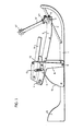
- a height-adjustable hold-down device has a part 2 (only visible in FIG. 2) which can be placed transversely over the instep and which is made of elastically deformable flat material, e.g. consists of rubber and the shape of the foot can be adjusted with its ends downward in order to press the foot against a base which is formed by the base plate 1.
- the hold-down part 2 that can be tensioned across the instep is fastened at its ends by means of clamping strips, of which only the screws serving to fix them can be seen in the drawing, to legs of a U-shaped hold-down clamp 3 running on one side of the foot.
- the hold-down bracket 3 can be pivoted up and down about a pivot axis 4 which is arranged in front of the foot horizontally and transversely to the longitudinal axis of the binding.
- the pivot axis 4 can (in the embodiment shown with broken lines in the drawing) along a guide rod 5 sloping obliquely backwards in the longitudinal center plane of the binding.
- the hold-down clamp 3 has a central bore 6 at the front through which the longitudinal guide rod 5 passes with play. The game is necessary to enable the hold-down bracket 3 to be pivoted about the pivot axis 4 when opening and closing the hold-down device 2, 3.
- the pivot axis 4 in this variant follows a circular path with the center in the axis of rotation 5 ".
- the lever arm 5 ' can also be changed in length to adapt the hold-down device 2, 3 to different foot sizes. For this purpose, it consists of two separate sections, each with an external thread, which are screwed into different internal threads of a screw nut part 5 "'.
- the other (lower) end of the semi-trailing arm 8 is articulated at 9 approximately in the plane of the base plate 1.
- a pawl 11 is articulated (at 10) which engages in a spring 12 the base plate 1 fixed teeth 13 is tensioned.
- a U-shaped actuating bracket 14 is arranged, which is attached to the two trailing arms 8 with the ends of its legs.
- 1 shows the actuating bracket 14 in its pressed-forward position, the semi-trailing arms 8 being in an upright position and the hold-down device 2, 3 taking up the open position.
- the hold-down bracket 3 with its pivot axis 4 is furthest forward and with its ends attached to the semi-trailing arms 8 in the highest possible position.
- the skier can slip in under the hold-down device 2, 3 or slip out from there.
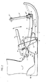
- the actuating bracket 14 in its rearwardly pulled position, the semi-trailing arms 8 being pivoted backwards about the axis 9 and the hold-down device 2, 3 assuming the closed position.
- the hold-down device 2, 3, with its pivot axis 4 is furthest to the rear and with its ends attached to the semi-trailing arms 8, as far down as the hold-down device 2 stretched over the instep allows.
- the operating bracket 14 is. a small swivel play relative to the semi-trailing arms 8, which swivel play is limited on the one hand by the pawl 11 and on the other hand by the pivot pin 7, which connects the semi-trailing arm 8 and hold-down bracket 3.
- the actuating bracket 14 pivots in the opening direction together with the semi-trailing arms 8, the actuating bracket 14 (as shown in particular in FIG. 1) presses the pawl 11 out of the toothing 13.
Landscapes
- Chemical & Material Sciences (AREA)
- Engineering & Computer Science (AREA)
- Combustion & Propulsion (AREA)
- Mechanical Engineering (AREA)
- Ocean & Marine Engineering (AREA)
- Footwear And Its Accessory, Manufacturing Method And Apparatuses (AREA)
Applications Claiming Priority (2)
| Application Number | Priority Date | Filing Date | Title |
|---|---|---|---|
| AT0313883A AT383962B (de) | 1983-09-01 | 1983-09-01 | Bindung fuer wassergleitschuhe |
| AT3138/83 | 1983-09-01 |
Publications (2)
| Publication Number | Publication Date |
|---|---|
| EP0144537A2 true EP0144537A2 (fr) | 1985-06-19 |
| EP0144537A3 EP0144537A3 (fr) | 1986-02-26 |
Family
ID=3545896
Family Applications (1)
| Application Number | Title | Priority Date | Filing Date |
|---|---|---|---|
| EP84109889A Withdrawn EP0144537A3 (fr) | 1983-09-01 | 1984-08-20 | Fixation de ski nautique |
Country Status (3)
| Country | Link |
|---|---|
| US (1) | US4624646A (fr) |
| EP (1) | EP0144537A3 (fr) |
| AT (1) | AT383962B (fr) |
Families Citing this family (12)
| Publication number | Priority date | Publication date | Assignee | Title |
|---|---|---|---|---|
| US5591060A (en) * | 1991-12-31 | 1997-01-07 | Forsyth; Michael | Retention assembly |
| US5194023A (en) * | 1992-01-24 | 1993-03-16 | Edward Stone | Individual propelled water craft |
| US5722867A (en) * | 1995-10-23 | 1998-03-03 | Lagrow; Michael C. | Reinforced shoe device |
| US6293577B1 (en) | 1996-10-03 | 2001-09-25 | Peter Shields | Foot binding assembly |
| US6648365B1 (en) | 1997-01-08 | 2003-11-18 | The Burton Corporation | Snowboard binding |
| US6855024B2 (en) * | 2002-04-29 | 2005-02-15 | Walter G. Rothschild | Skis to walk on water |
| US8845372B2 (en) | 2011-03-23 | 2014-09-30 | Jerome Connelly Farmer | Standing watercraft with torso-mounted paddles |
| US9126097B2 (en) * | 2013-02-12 | 2015-09-08 | Jakob Diego Llanes Fettig | Snowboard accessory |
| US9272761B2 (en) | 2013-08-27 | 2016-03-01 | Jerome C. Farmer | Angular velocity-controlled pontoon propulsion system |
| US9675867B2 (en) | 2015-07-28 | 2017-06-13 | X-Sports | Ski binding equipment |
| DE102019127483A1 (de) * | 2019-10-11 | 2021-04-15 | Dalion Watersports UG (haftungsbeschränkt) | Bindung |
| US11932358B2 (en) * | 2021-03-26 | 2024-03-19 | Chung Kim | Flotation system and shoes thereof |
Family Cites Families (7)
| Publication number | Priority date | Publication date | Assignee | Title |
|---|---|---|---|---|
| DE288149C (fr) * | 1913-03-27 | |||
| US2165547A (en) * | 1936-12-16 | 1939-07-11 | Cortlandt T Hill | Foot attachment for skis and the like |
| US2382149A (en) * | 1944-02-21 | 1945-08-14 | John M Hartman | Heel support for water skis |
| US2540576A (en) * | 1949-05-03 | 1951-02-06 | William V Goodhue | Water ski binding |
| US3143750A (en) * | 1963-04-22 | 1964-08-11 | Anthony M Kluge | Binding for water skis |
| US3360812A (en) * | 1966-06-09 | 1968-01-02 | Anthony M. Kluge | Binding for water skis |
| US3508288A (en) * | 1968-04-29 | 1970-04-28 | Arlie F Lockwood | Releasable water ski boot structure |
-
1983
- 1983-09-01 AT AT0313883A patent/AT383962B/de not_active IP Right Cessation
-
1984
- 1984-08-20 EP EP84109889A patent/EP0144537A3/fr not_active Withdrawn
- 1984-08-22 US US06/643,115 patent/US4624646A/en not_active Expired - Fee Related
Also Published As
| Publication number | Publication date |
|---|---|
| ATA313883A (de) | 1987-02-15 |
| US4624646A (en) | 1986-11-25 |
| EP0144537A3 (fr) | 1986-02-26 |
| AT383962B (de) | 1987-09-10 |
Similar Documents
| Publication | Publication Date | Title |
|---|---|---|
| DE69726391T2 (de) | Einspurrollschuh mit herausnehmbarem Schuh | |
| DE2800187A1 (de) | Ski- und eislaufschuh | |
| DE4007667C1 (fr) | ||
| CH672432A5 (fr) | ||
| EP0144537A2 (fr) | Fixation de ski nautique | |
| CH679110A5 (fr) | ||
| DE60013364T2 (de) | Befestigungsvorrichtung für ein Schneesportgerät | |
| DE1578752B2 (de) | Fersensicherheitshalter fuer eine skibindung | |
| DE4424737C1 (de) | Snowboardbindung | |
| CH616344A5 (fr) | ||
| EP0784943B1 (fr) | Chaussure de ski | |
| DE69602509T2 (de) | Schuhrückhaltevorrichtung auf einem Snowboard bzw. Ski oder ähnlichem | |
| DE693857C (de) | Skibindung mit federndem, in seiner Spannung veraenderlichem Fersenzugglied | |
| DE1428991B2 (de) | Sohlenauflagevorrichtung für eine den Schuh an Spitze und Absatz abstützende Sicherheitsskibindung | |
| DE3916453C2 (fr) | ||
| DE2906520A1 (de) | Langlauf-skibindung | |
| DE3529040A1 (de) | Leiterfuss | |
| DE3702094A1 (de) | Halteeinrichtung fuer einen schuh an einem alpin-surf-geraet | |
| WO1997039808A1 (fr) | Fixation de planche a neige | |
| DE608273C (de) | Skibindung mit nach vorn an die Zehenbacken verlegtem Fersenzugstrammer | |
| CH679264A5 (fr) | ||
| DE102024123208A1 (de) | Snowboardbindung | |
| DE2635621C3 (de) | Fersenbindung für einen Ski | |
| DE1578752C3 (de) | Fersensicherheitshalter fur eine Skibindung | |
| DE2523927A1 (de) | An einem ski angeordnete bremsvorrichtung |
Legal Events
| Date | Code | Title | Description |
|---|---|---|---|
| PUAI | Public reference made under article 153(3) epc to a published international application that has entered the european phase |
Free format text: ORIGINAL CODE: 0009012 |
|
| AK | Designated contracting states |
Designated state(s): AT CH DE FR GB IT LI NL SE |
|
| PUAL | Search report despatched |
Free format text: ORIGINAL CODE: 0009013 |
|
| AK | Designated contracting states |
Designated state(s): AT CH DE FR GB IT LI NL SE |
|
| 17P | Request for examination filed |
Effective date: 19860802 |
|
| 17Q | First examination report despatched |
Effective date: 19870422 |
|
| R17C | First examination report despatched (corrected) |
Effective date: 19870430 |
|
| STAA | Information on the status of an ep patent application or granted ep patent |
Free format text: STATUS: THE APPLICATION IS DEEMED TO BE WITHDRAWN |
|
| 18D | Application deemed to be withdrawn |
Effective date: 19880608 |