EP0144547A2 - Compresseur à piston pour milieux gazeux - Google Patents
Compresseur à piston pour milieux gazeux Download PDFInfo
- Publication number
- EP0144547A2 EP0144547A2 EP84110223A EP84110223A EP0144547A2 EP 0144547 A2 EP0144547 A2 EP 0144547A2 EP 84110223 A EP84110223 A EP 84110223A EP 84110223 A EP84110223 A EP 84110223A EP 0144547 A2 EP0144547 A2 EP 0144547A2
- Authority
- EP
- European Patent Office
- Prior art keywords
- valve
- openings
- inlet
- valve plate
- cylinder
- Prior art date
- Legal status (The legal status is an assumption and is not a legal conclusion. Google has not performed a legal analysis and makes no representation as to the accuracy of the status listed.)
- Withdrawn
Links
Images

Classifications
-
- F—MECHANICAL ENGINEERING; LIGHTING; HEATING; WEAPONS; BLASTING
- F04—POSITIVE - DISPLACEMENT MACHINES FOR LIQUIDS; PUMPS FOR LIQUIDS OR ELASTIC FLUIDS
- F04B—POSITIVE-DISPLACEMENT MACHINES FOR LIQUIDS; PUMPS
- F04B39/00—Component parts, details, or accessories, of pumps or pumping systems specially adapted for elastic fluids, not otherwise provided for in, or of interest apart from, groups F04B25/00 - F04B37/00
- F04B39/10—Adaptations or arrangements of distribution members
- F04B39/1073—Adaptations or arrangements of distribution members the members being reed valves
-
- Y—GENERAL TAGGING OF NEW TECHNOLOGICAL DEVELOPMENTS; GENERAL TAGGING OF CROSS-SECTIONAL TECHNOLOGIES SPANNING OVER SEVERAL SECTIONS OF THE IPC; TECHNICAL SUBJECTS COVERED BY FORMER USPC CROSS-REFERENCE ART COLLECTIONS [XRACs] AND DIGESTS
- Y10—TECHNICAL SUBJECTS COVERED BY FORMER USPC
- Y10T—TECHNICAL SUBJECTS COVERED BY FORMER US CLASSIFICATION
- Y10T137/00—Fluid handling
- Y10T137/7722—Line condition change responsive valves
- Y10T137/7837—Direct response valves [i.e., check valve type]
- Y10T137/7838—Plural
- Y10T137/7839—Dividing and recombining in a single flow path
- Y10T137/784—Integral resilient member forms plural valves
Definitions
- the invention relates to a reciprocating compressor for gaseous media according to the preamble of claim 1.
- valve arrangements of this type are known. Instead of lamellae, which only cover one opening at a time, a circular or semicircular ring, which covers several openings and is usually attached to two handlebars, can be used. All currently known valve arrangements of this type have i.a. the disadvantage that their opening cross-section (valve gap cross-section) is very small in relation to the available piston area and therefore only average piston speeds of up to approx. 4 m / sec can be achieved.
- the delivery volume of a cylinder unit of a reciprocating compressor is limited by the available valve gap cross-section and the maximum permissible gap speed of the medium. Since with valves of this type, for example, only flow velocities of at most 75 m / sec are acceptable for the medium of air, since otherwise pressure losses and heating become too great, a substantial increase in delivery rate can only be achieved indirectly by a substantial increase in the valve gap cross section.
- the valve gap cross section is the product of the circumferential length of the opening gap, the average gap height (average lamella stroke) and the number of valve openings.
- the maximum permissible mean lamella stroke depends on the opening and closing frequency of the lemelles and their masses, and experience has shown that at a maximum achievable compressor speed of 3 () 0 rpm and the medium air, for reasons of service life, should not exceed 1.5 mm Valve openings with one Diameter over 7 mm pointless. Accordingly, an increase in the total valve gap area cannot be achieved by increasing the valve openings, but rather only by increasing the number of valve openings.
- the invention has for its object to design a reciprocating compressor for gaseous media, especially with regard to its valve arrangement, that within a given piston area, taking into account the aforementioned functional criteria, a much larger valve gap area is achieved than in known valve arrangements, without thereby significantly increasing the manufacturing outlay.
- valve plate in a reciprocating compressor of the type mentioned, this object is achieved in that in the valve plate successive valve openings on the entire inner circle with the same angular pitch and on the outer circle valve openings in the same number as on the inner circle, but offset by half the angular pitch are and that the inlet and outlet valve lamellae each consist of a disk-shaped area drilled through in the center, onto which narrow, radiating arms are formed, which at their ends merge into preferably circular extensions.
- outlet openings lie on the outer circle and the inlet openings lie on the inner circle.
- the inlet openings on the cylinder head side are surrounded by a tubular inlet duct which penetrates the cylinder head cover in a sealed manner and divides the cylinder head chamber into a suction and an external pressure chamber.
- the inlet channel downstream at the inner end with a bottom which contains congruent openings with the inlet openings in the valve plate and is also formed on its cylinder side in the region of the webs between the inlet openings as a stroke limiter for the arms and the circular extensions of the outlet valve lamellae is.
- the gas flow sucked in through the inlet openings can be further favorably influenced by the fact that the inlet openings on their inlet side are approximately pear-shaped in cross-section towards the cylinder axis corresponding to the free space between the radiating arms of the outlet valve lamellae and that the pear-shaped opening cross-section in the valve plate on the Narrow side merges via an inclined wall section into the circular opening on the cylinder side of the valve plate.
- the advantages that the invention offers are primarily to be seen in an optimal use of the predetermined piston area, which is achieved by an arrangement of inlet and outlet openings offset by half an angular pitch in equal numbers. Thanks to this staggered arrangement, the inlet and outlet valve fins can each be from a disk-shaped area pierced in the center stand, on which narrow, radially extending valve fins are molded. With a given piston area, this configuration enables the largest possible number of inlet and outlet openings to be accommodated with an optimal hole diameter and thus an overall increase in the total valve gap area.
- the inlet openings are provided on the inner circle and are enclosed by a tubular inlet channel, this results in a central inflow of the sucked-in medium.
- the outlet openings open into an annular space between the inlet duct and the jacket of the cylinder head space, which results in a concentric outflow of the compressed medium and at the same time the pressure losses can be kept low due to the favorable flow conditions.
- the use of the outlet valves in the edge area of the valve plate instead of in the inner area also has the advantage that more intensive cooling is possible here, which helps to avoid undesired heating of the elements of the outlet valves. This is of particular importance for the compression of media with a relatively high compression exponent, e.g. Air.
- valve gap area achieved by the invention enables, by increasing the piston speed to values of up to 7 m / sec, a simple increase in the delivery rate and thus a specific reduction in the manufacturing costs of a reciprocating piston compressor.
- Higher piston speeds also allow the use of high-speed diesel engines (approx. 3000 rpm) as a directly coupled drive unit as an alternative to the electric motor.
- the good cooling of the exhaust valve fins like their stroke limiter also leads to a reduction in the risk of coking of the lubricating oil.
- the concentric inflow and outflow of the medium results in lower pressure losses and thus less heating of the valve elements.
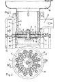
- FIG. 1 shows the upper end of the cylinder 1 of a reciprocating compressor, a valve plate 2 as an intermediate member between the cylinder 1 and the cylinder head 3.
- Cylinder 1 and cylinder head 3 are surrounded by jackets 4 and 4a, which enclose annular spaces for receiving a coolant .
- the cylinder head cover 5 is penetrated by a tubular inlet duct 6, which contains an inner floor 7 and is connected via this to the valve plate 2.
- a fastening screw consisting of a screw bolt 8 and a nut 9, which firmly connects the aforementioned parts, a stroke limiter 10 lying on the cylinder side against the valve plate 2 and the valve plates.
- a smaller through-bore is contained in the base 7, in the valve plate 2 and in the stroke limiter 10, in which a pin 11 is held in a form-fitting manner to prevent rotation.
- a filter 12 is indicated, through which the sucked medium enters the inlet channel 6.
- the annular space 13 located outside the inlet channel 6 in the interior of the cylinder head 3 forms the pressure space from which the compressed medium exits through an outlet connection 14.
- the valve plate 2 contains, on two circles concentric to the cylinder axis, a number of inlet and outlet openings, which are arranged on the outer and inner circles over the entire circumference in each case in the same number and with the same angular division, but offset from one another by half the angular division.
- the openings on the outer circle form the outlet openings 16 and the openings on the inner circle form the inlet openings 15.
- the division angle is approximately 30.
- the hole circle of the inlet openings 15 is approximately 20% smaller than that of the outlet openings 16.
- the inlet openings 15 are elongated on their inlet side for a better inflow towards the cylinder axis approximately pear-shaped, as shown in Fig. 2.
- the pear-shaped extension of the Opening in valve plate 2 merges via an inclined wall section 17 into the circular opening on the cylinder side of valve plate 2.
- the manufacture of the inlet and outlet openings in steel and cast iron is expediently carried out by mechanical processing.
- the openings can be created by means of die-casting, with post-processing only being necessary on the two sealing surfaces.
- FIGS. 3 and 4 consist of a disk-shaped area 18 and 19, on which narrow arms 20 and 21, which extend radially outwards, are formed, which are circular at their ends Skip extensions 22 and 23, respectively.
- a central bore 24 or 25 and a smaller bore 26 or 27 are contained in the disk-shaped area.
- the central bores 24 and 25 are penetrated by the bolt 8 of the fastening screw in the installed position of the lamellar disks, which, in addition to fastening the aforementioned parts, also serves to fasten the lamellar disks.
- the smaller bores 26 and 27 receive the pin 11.
- the configuration described is particularly suitable for reciprocating compressors with a piston diameter of 70 to 100 mm.
- the inlet lamella disc has e.g. a thickness of 0.15 mm and the outlet lamella disc a thickness of 0.3 mm.
- the preferred material is corrosion-resistant spring steel. They can be produced in the usual way by punching.
- the stroke limiter 10 for the inlet valve plates has the same cross-sectional shape as the inlet plate disk according to FIG. 4. Its surface facing the valve plate 2 is spherical.
- the web areas between the inlet openings 15 on the underside of the bottom 7 of the inlet channel 6 serve as stroke limiters for the exhaust valve lamellae.
- These web areas, which form the contact surfaces for the arms 20 and the extensions 22 of the exhaust valve lamellae, are in their shape the shape of the outline of the exhaust lamella disk according to FIG 3 adapted. Their shape is illustrated in the sectional view in FIG. 2.
- the web regions serving as contact surfaces are spherically shaped.
- pear-shaped seals 29 made of a flexible plastic material are inserted at these points.
- the thickness of the pear-shaped seals is approximately 1.2 times the thickness of the outlet disk.
- FIG 5 shows a modified embodiment in the area of the bottom of the input channel 6a.
- the floor 7a not simultaneously designed as a stroke limiter for the outlet fins. Rather, a stroke limiter 31 is provided as an additional component, which is designed in the same way as the stroke limiter 10 for the inlet lamellae.
- the bottom 7a is at a distance from the valve plate 2, with nozzles 30 directed towards and adjoining the valve plate 2 being formed on the bottom 7a and sealingly connecting to the inlet openings 15 in the valve plate 2.
- a central attachment is provided for all components with the aid of a screw 32, which has an elongated threaded section on which a second nut 33 is mounted, which is used for the independent attachment of the inlet channel 6a to the valve plate 2.
Landscapes
- Engineering & Computer Science (AREA)
- Mechanical Engineering (AREA)
- General Engineering & Computer Science (AREA)
- Compressor (AREA)
Applications Claiming Priority (2)
| Application Number | Priority Date | Filing Date | Title |
|---|---|---|---|
| DE3333468 | 1983-09-16 | ||
| DE3333468 | 1983-09-16 |
Publications (2)
| Publication Number | Publication Date |
|---|---|
| EP0144547A2 true EP0144547A2 (fr) | 1985-06-19 |
| EP0144547A3 EP0144547A3 (fr) | 1986-10-15 |
Family
ID=6209247
Family Applications (1)
| Application Number | Title | Priority Date | Filing Date |
|---|---|---|---|
| EP19840110223 Withdrawn EP0144547A3 (fr) | 1983-09-16 | 1984-08-28 | Compresseur à piston pour milieux gazeux |
Country Status (3)
| Country | Link |
|---|---|
| US (1) | US4565507A (fr) |
| EP (1) | EP0144547A3 (fr) |
| JP (1) | JPS6079184A (fr) |
Families Citing this family (16)
| Publication number | Priority date | Publication date | Assignee | Title |
|---|---|---|---|---|
| US5201644A (en) * | 1987-12-23 | 1993-04-13 | 3H Invent A/S | Valve arrangement for pump or compressor |
| US5266015A (en) * | 1992-02-13 | 1993-11-30 | Tecumseh Products Company | Compressor suction and discharge valve assembly |
| US5213125A (en) * | 1992-05-28 | 1993-05-25 | Thomas Industries Inc. | Valve plate with a recessed valve assembly |
| US5327932A (en) * | 1993-04-19 | 1994-07-12 | Thomas Industries Inc. | Valve restraint enhancement |
| US7390176B2 (en) * | 2001-10-05 | 2008-06-24 | Carrier Corporation | Multi-port suction reed valve with optimized tips |
| NZ526361A (en) * | 2003-05-30 | 2006-02-24 | Fisher & Paykel Appliances Ltd | Compressor improvements |
| DE102004047159B4 (de) * | 2004-09-29 | 2006-09-07 | Danfoss Compressors Gmbh | Kolbenverdichter, insbesondere hermetischer Kältemittelverdichter |
| FR2895037A1 (fr) * | 2005-12-20 | 2007-06-22 | Tecumseh Europ S A Sa | Dispositif a clapets pour compresseur de fluide et compresseur de fluide |
| JP2008248794A (ja) * | 2007-03-30 | 2008-10-16 | Anest Iwata Corp | 圧縮機の逆止弁 |
| US20130121860A1 (en) * | 2011-11-10 | 2013-05-16 | Gene Bluhm | Retrofit of a reciprocating compressor with a concentric valve |
| TWI621776B (zh) * | 2016-01-15 | 2018-04-21 | Wen-San Chou | 空壓機之汽缸出氣構造改良 |
| TWI608168B (zh) * | 2016-01-18 | 2017-12-11 | 周文三 | 空氣壓縮機之汽缸出氣結構改良 |
| TWI626376B (zh) * | 2016-01-20 | 2018-06-11 | Wen-San Chou | 空氣壓縮機之汽缸出氣構造改良 |
| CN106286231B (zh) * | 2016-10-25 | 2019-03-08 | 马德宝真空设备集团有限公司 | 一种往复式真空泵的吸排气阀组件 |
| JP7165670B6 (ja) * | 2017-03-27 | 2023-08-18 | ブルクハルト コンプレッション アーゲー | ピストンコンプレッサバルブ用のバルブクロージャおよびそのバルブクロージャを動作させるための方法 |
| US10683860B2 (en) * | 2017-03-27 | 2020-06-16 | Burckhardt Compression Ag | Piston compressor valve and method for operating a piston compressor valve |
Family Cites Families (9)
| Publication number | Priority date | Publication date | Assignee | Title |
|---|---|---|---|---|
| US1627680A (en) * | 1923-11-08 | 1927-05-10 | Carl W Vollmann | Valve for gas compressors |
| DE507217C (de) * | 1927-01-14 | 1930-09-15 | Ingersoll Rand Co | Federplattenventil |
| US2682280A (en) * | 1950-08-02 | 1954-06-29 | Gen Electric | Interwoven exhaust valve |
| US2725183A (en) * | 1951-01-10 | 1955-11-29 | Carrier Corp | Valves for reciprocating compressors |
| FR1080792A (fr) * | 1952-05-14 | 1954-12-13 | Thomson Houston Comp Francaise | Perfectionnements aux compresseurs à mouvement alternatif |
| DE1500015A1 (de) * | 1965-09-09 | 1969-05-14 | Kurt Ehmann | Ventil fuer Kolbenkompressoren |
| JPS5820394B2 (ja) * | 1978-01-24 | 1983-04-22 | サンデン株式会社 | 流体吸排装置 |
| DE2910597A1 (de) * | 1979-03-17 | 1980-09-18 | Volkswagenwerk Ag | Ventilanordnung fuer kompressoren |
| DE3335725A1 (de) * | 1983-10-01 | 1985-04-11 | Boge Kompressoren Otto Boge Gmbh & Co Kg, 4800 Bielefeld | Ventil fuer kolbenkompressoren |
-
1984
- 1984-08-28 EP EP19840110223 patent/EP0144547A3/fr not_active Withdrawn
- 1984-09-12 JP JP59189854A patent/JPS6079184A/ja active Pending
- 1984-09-17 US US06/650,892 patent/US4565507A/en not_active Expired - Fee Related
Also Published As
| Publication number | Publication date |
|---|---|
| US4565507A (en) | 1986-01-21 |
| EP0144547A3 (fr) | 1986-10-15 |
| JPS6079184A (ja) | 1985-05-04 |
Similar Documents
| Publication | Publication Date | Title |
|---|---|---|
| DE102004047159B4 (de) | Kolbenverdichter, insbesondere hermetischer Kältemittelverdichter | |
| DE602004000553T2 (de) | Saugventil in Lamellenausführung für einen Verdichter | |
| DE4420865C2 (de) | Kältekompressor mit einem kugelförmigen Auslaßventil | |
| DE4430137B4 (de) | Mehrteiliger, gekühlter Kolben für Verbrennungsmotoren | |
| DE4446302C2 (de) | Taumelscheibenkompressor mit Druckschwankungsdämpfer | |
| DE69015168T2 (de) | Kältemittelkompressorkonstruktion. | |
| DE4110647C2 (de) | Kolbenverdichter | |
| DE10203579A1 (de) | Gasansaugvorrichtung für Hubkolbenverdichter | |
| DE10244588A1 (de) | Ölabscheider | |
| DE60214070T2 (de) | Verdichterkolben | |
| DE60309280T2 (de) | Integriertes Ringventil für einen Kompressorkolben | |
| DE3839172A1 (de) | Taumelscheibenkompressor | |
| DE202020101747U1 (de) | Membranpumpe und Kaffeemaschine mit Membranpumpe | |
| EP1702162A1 (fr) | Compresseur a piston pour comprimer des substances gazeuses dans au moins deux chambres de travail | |
| DE19813046A1 (de) | Hubkolbenkompressor | |
| DE69018831T2 (de) | Ansaugventil für eine pumpe zum auffangen von verunreinigungen. | |
| DE2726089A1 (de) | Ventilplatte | |
| DE2846419A1 (de) | Kolbenzylinder fuer verdichter | |
| DE19903025C2 (de) | Kolbenverdichter für gasförmige Medien | |
| EP0407865A2 (fr) | Piston pour amortisseur de vibrations, en particulier pour amortisseurs de véhicules à moteur | |
| DE2060663A1 (de) | Ventilsatz fuer Kolbenverdichter | |
| DE60305864T2 (de) | Druckventilhubbegrenzer eines Verdichters | |
| DE10255680B4 (de) | Axialkolbenverdichter, insbesondere CO 2-Verdichter für Fahrzeug-Klimaanlagen mit geteiltem Zylinderkopf | |
| DE3335725A1 (de) | Ventil fuer kolbenkompressoren | |
| DE4326366A1 (de) | Kompressor der Taumelscheibenbauart |
Legal Events
| Date | Code | Title | Description |
|---|---|---|---|
| PUAI | Public reference made under article 153(3) epc to a published international application that has entered the european phase |
Free format text: ORIGINAL CODE: 0009012 |
|
| AK | Designated contracting states |
Designated state(s): AT BE CH DE FR GB IT LI LU NL SE |
|
| PUAL | Search report despatched |
Free format text: ORIGINAL CODE: 0009013 |
|
| RHK1 | Main classification (correction) |
Ipc: F04B 39/10 |
|
| AK | Designated contracting states |
Kind code of ref document: A3 Designated state(s): AT BE CH DE FR GB IT LI LU NL SE |
|
| STAA | Information on the status of an ep patent application or granted ep patent |
Free format text: STATUS: THE APPLICATION IS DEEMED TO BE WITHDRAWN |
|
| 18D | Application deemed to be withdrawn |
Effective date: 19870416 |
|
| RIN1 | Information on inventor provided before grant (corrected) |
Inventor name: REIMERS, REIMER |