EP0144575A2 - Pompage avec cryosorption - Google Patents
Pompage avec cryosorption Download PDFInfo
- Publication number
- EP0144575A2 EP0144575A2 EP84111007A EP84111007A EP0144575A2 EP 0144575 A2 EP0144575 A2 EP 0144575A2 EP 84111007 A EP84111007 A EP 84111007A EP 84111007 A EP84111007 A EP 84111007A EP 0144575 A2 EP0144575 A2 EP 0144575A2
- Authority
- EP
- European Patent Office
- Prior art keywords
- cryosorption
- cryocondensation
- container
- magnetic field
- evacuated
- Prior art date
- Legal status (The legal status is an assumption and is not a legal conclusion. Google has not performed a legal analysis and makes no representation as to the accuracy of the status listed.)
- Granted
Links
- 239000007789 gas Substances 0.000 claims abstract description 22
- 239000003463 adsorbent Substances 0.000 claims abstract description 18
- 239000002826 coolant Substances 0.000 claims description 2
- 239000000463 material Substances 0.000 abstract 1
- 229910052734 helium Inorganic materials 0.000 description 23
- 239000001307 helium Substances 0.000 description 23
- SWQJXJOGLNCZEY-UHFFFAOYSA-N helium atom Chemical compound [He] SWQJXJOGLNCZEY-UHFFFAOYSA-N 0.000 description 23
- 229910052722 tritium Inorganic materials 0.000 description 10
- YZCKVEUIGOORGS-NJFSPNSNSA-N Tritium Chemical compound [3H] YZCKVEUIGOORGS-NJFSPNSNSA-N 0.000 description 9
- 230000004927 fusion Effects 0.000 description 7
- 239000007788 liquid Substances 0.000 description 6
- 238000005086 pumping Methods 0.000 description 6
- 230000005250 beta ray Effects 0.000 description 4
- YZCKVEUIGOORGS-OUBTZVSYSA-N Deuterium Chemical compound [2H] YZCKVEUIGOORGS-OUBTZVSYSA-N 0.000 description 3
- 230000015556 catabolic process Effects 0.000 description 3
- 238000006243 chemical reaction Methods 0.000 description 3
- 238000006731 degradation reaction Methods 0.000 description 3
- 229910052805 deuterium Inorganic materials 0.000 description 3
- OKTJSMMVPCPJKN-UHFFFAOYSA-N Carbon Chemical compound [C] OKTJSMMVPCPJKN-UHFFFAOYSA-N 0.000 description 2
- 230000002411 adverse Effects 0.000 description 2
- 229910052799 carbon Inorganic materials 0.000 description 2
- 238000003795 desorption Methods 0.000 description 2
- 239000000696 magnetic material Substances 0.000 description 2
- 238000010276 construction Methods 0.000 description 1
- 230000000694 effects Effects 0.000 description 1
- 230000004907 flux Effects 0.000 description 1
- 239000000446 fuel Substances 0.000 description 1
- 239000002808 molecular sieve Substances 0.000 description 1
- 239000002245 particle Substances 0.000 description 1
- URGAHOPLAPQHLN-UHFFFAOYSA-N sodium aluminosilicate Chemical compound [Na+].[Al+3].[O-][Si]([O-])=O.[O-][Si]([O-])=O URGAHOPLAPQHLN-UHFFFAOYSA-N 0.000 description 1
- 229910001220 stainless steel Inorganic materials 0.000 description 1
- 239000010935 stainless steel Substances 0.000 description 1
Images


Classifications
-
- F—MECHANICAL ENGINEERING; LIGHTING; HEATING; WEAPONS; BLASTING
- F04—POSITIVE - DISPLACEMENT MACHINES FOR LIQUIDS; PUMPS FOR LIQUIDS OR ELASTIC FLUIDS
- F04B—POSITIVE-DISPLACEMENT MACHINES FOR LIQUIDS; PUMPS
- F04B37/00—Pumps having pertinent characteristics not provided for in, or of interest apart from, groups F04B25/00 - F04B35/00
- F04B37/06—Pumps having pertinent characteristics not provided for in, or of interest apart from, groups F04B25/00 - F04B35/00 for evacuating by thermal means
- F04B37/08—Pumps having pertinent characteristics not provided for in, or of interest apart from, groups F04B25/00 - F04B35/00 for evacuating by thermal means by condensing or freezing, e.g. cryogenic pumps
-
- Y—GENERAL TAGGING OF NEW TECHNOLOGICAL DEVELOPMENTS; GENERAL TAGGING OF CROSS-SECTIONAL TECHNOLOGIES SPANNING OVER SEVERAL SECTIONS OF THE IPC; TECHNICAL SUBJECTS COVERED BY FORMER USPC CROSS-REFERENCE ART COLLECTIONS [XRACs] AND DIGESTS
- Y10—TECHNICAL SUBJECTS COVERED BY FORMER USPC
- Y10S—TECHNICAL SUBJECTS COVERED BY FORMER USPC CROSS-REFERENCE ART COLLECTIONS [XRACs] AND DIGESTS
- Y10S417/00—Pumps
- Y10S417/901—Cryogenic pumps
Definitions
- This invention relates to a cryosorption pump having an improved construction for high vacuum condition in a pumping system.
- a usual cryosorption pump is provided with a pumping chamber to be evacuated to obtain the high vacuum condition and a cryosorption member having an extremely low temperature surface, i.e. cryosurface, is disposed at substantially the central portion of the pumping chamber so as to be cooled to a temperature of about 4.2K (absolute temperature) by means of liquid helium.
- a helium gas is not condensed and evacuated on the cryosurface at the temperature of about 4.2K for the reason that the helium gas has high equilibrium vapour pressure.
- an adsorbent such as active carbon and molecular sieves, or an condensed gas layer composed of such as Ar or C0 2 gas.
- a further cryocondensation member (or members) on which no adsorbent is applied is (or are) arranged so as to surround the cryosorption member on which the adsorbent is applied.
- the former mentioned cryocondensation member (or'members) serves (or serve) to preliminarily condense gases other than the helium g ⁇ S which are condensed at a temperature of about 4.2K thereby to reduce an excessive gas load on the cryosurface of the later mentioned cryosorption member on which the adsorbent is applied.
- the tritium emits ⁇ -rays (a kind of energetic electron) each having the maximum energy of 18.6 KeV and average energy of 5.96 KeV when the tritium decays with a half life of 12.3 years.
- the ⁇ -rays are emitted from the tritium once condensed on the cryosurface substantially straightly in the atmosphere in a case where no magnetic field is.generated therein, some of ⁇ -rays impinge on the cryosurface on which the adsorbent is applied.
- the helium gas adsorbed on the adsorbent is usually very weakly adsorbed, so that a large amount of the helium is desorbed by the impact of the ⁇ -rays, which is generally called "electron impact desorption". This phenomenon adversely results in the lowering of the effective pumping speed of the helium on the_cryosurface. This is not advantageous for the cryopumping operation.
- An object of this invention is to obviate problems in a cryosorption pump of the prior type and provide an improved cryosorption pump capable of preventing electrons or ⁇ -rays from the impingement on a cryosurface on which helium gas is adsorbed for example in a nuclear fusion system thereby to increase the effective pumping speed for helium gas.
- a cryosorption pump for high vacuum condition to be evacuated and the cryosorption pump comprises a container defining therein a space connected to an opening of a chamber to be evacuated, a cryosorption panel which is located in the container and on which an adsorbent is applied, a plurality of cryocondensation chevron baffles arranged on both sides of the cryosorption panel so as to exhibit the longitudinal side surfaces thereof to the opening of the chamber, a magnetic field generating member arranged to generate a magnetic field around the cryosorption panel, a unit for supplying cooling medium to the cryosorption panel and chevron baffles, and an exhaust pipe for exhausting gases in the container outwardly.
- a coil means or magnet means is located in a cryopumping container for generating a magnetic field around the cryosorption panel, so that electron such as ⁇ -rays emitted' from a tritium, for example, are subjected to cyclotron gyration under the affect of the magnetic field thereby to prevent the electron impact against the cryosorption panel on which helium is adsorbed, thus increasing the exhausting speed thereof as well as lowering the gas condensing or pumping performance and reducing the degradation of an adsorbent applied on the cryosorption panel.
- FIG. 1A shows a perspective view of a crycsorp- tion pump 3 connected to a chamber 1 to be subjected to evacuating operation through an opening 2 formed on one side wall of the chamber 1.
- the cryosorption pump 3 generally comprises a container 4 made of a non-magnetic material such as stainless steel airtightly coupled to the wall of the chamber 1 provided with the opening 2, a plurality of cryosorption chevron baffles 5 parallelly disposed in the container for condensing and evacuating at a temperature of about 4.2K, a hollow cryosorption panel 6 also disposed in the container 4 for evacuating nonccndensa- ble gases by the cryocondensation chevron baffles 5 at a temperature of about 4.2K, and coil means 7 arranged to surround the cryosorption panel 6 for generating magnetic field.
- a container 4 made of a non-magnetic material such as stainless steel airtightly coupled to the wall of the chamber 1 provided with the opening 2,
- the cryocondensation chevron baffles 5 are arranged in parallel on both sides of the cryosorption panel 6 so as to exhibit their longitudinal side surfaces to the opening of the chamber 1 as shown in FIG. 1.
- An exhaust pipe 8 is connected to one wall of the container 4 as shown in FIG. 2.
- An adsorbent 13 such as an active carbon is applied on the outer surface of the cryosorption panel 6.
- a reservoir 9 is disposed in the container 4 for storing liquid helium which circulates through pipes 10 attached to the cryocondensation chevron baffles 5 to cool the same and is also supplied inside hollow portion of the cryosorption panel 6 through a pipe 11 to cool the same.
- the supply of the liquid helium from the outside of the container 4 into the reservoir 9 or the take-out of the liquid helium therefrom is performed through pipes 12.
- the pipes 10 may be preferably arranged at the inner top portions of the cryocondensation chevron baffles 5 as shown in FIG. 1B.
- the leading ends 7A of the coil means 7 project outwardly of the container 4.
- FIG. 2 is a schematic vertical sectional view of the cryosorption pump 3 shown in FIG. 1 for facilitating the understanding of the arrangement of the constructional elements described before, but does not critically accord with those shown in FIG. 1 in the positional relationship and the supply pipes 11 and 12 and the leading ends 7A of the coil means 7 are now eliminated.
- the cryosorption pump 3 shown in FIGS. 1 and 2 operates as follows.
- the chamber 1 is beforehand evacuated so as to obtain the vacuum condition therein to a certain extent.
- the liquid helium is circulated from the reservoir 9 through the pipes 10 to cool the cryocondensation chevron baffles 5.
- the coil means 7 is energized to generate the magnetic field near the cryosorption panel 6 and the liquid helium is then introduced into the hollow portion of the cryosorption panel 6 through the pipe 11 to cool the same.
- a cryosorption pump of the type described above for a vacuum system of a nuclear fusion system in which D-T (deuterium-tritium) reaction is carried out
- the deuterium or tritium which is a fuel of a nuclear fusion reaction is condensed on the surfaces of the cryocondensation chevron baffles 5.
- the helium gas as an ash produced by the nuclear fusion reaction is not condensed on the cryosorption chevron baffles 5 at a temperature of about 4.2K and is then adsorbed by the adsorbent 13 applied on the cryosorption panel 6.
- the tritium decays and emits ⁇ -rays each having the maximum energy of 18.6 KeV and average energy of 5.69 KeV.
- the helium once adsorbed thereon is desorbed by the so-called electron impact desorption, which results in the degradation of performance of the cryosorption pump 3.
- the adsorbent on the cryosorption panel 6 is composed of condensed gas layers such as Ar, Xe and C0 2 , these gases are also desorbed by the electron impact, which also results in the degradation of the adsorbent itself.
- the coil means 7 is energized to generate the magnetic field around the cryosorption panel 6 and when the ⁇ -rays will pass the magnetic field, cyclotron gyration is caused by the magnetic field so that the ⁇ -rays will not impact against the adsorbent 13 on the cyrosorption panel 6.
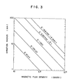
- FIG. 3 shows a graph representing the relationship between the cyclotron gyration radius of the ⁇ -ray and the magnetic flux density, and as can be understood from FIG. 3, the ⁇ -ray carrys out the cyclotron gyration with the radius of less than several mm in the magnetic field having intensity of from several hundred gausses to several thousand gausses.
- the cryosorption pump 3 provided with the coil means 7 arranged as shown in FIG. 1 or 2, the ⁇ -rays emitted from the tritium condensed on the cryocondensation chevron baffles 5 are gyrated by the magnetic field generated by the coil means 7, and thus, the ⁇ -rays do not reach the cryosorption panel 6 and the helium adsorbed on the adsorbent 13 thereon is not adversely desorbed.
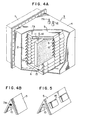
- FIG. 4A shows another embodiment of the cryosorption pump according to this invention, and in this embodiment, coil means 7B is disposed in contact with the respective cryocondensation chevron baffles 5 preferably at and along inner top portions thereof as shown in FIG. 4B instead of the separate coil arrangement shown in FIG. 1. Moreover, in this coil arrangement, it is desirable to use superconducting coil means 7B to disperse thermal energy of the coil means 7B and to reduce thermal load to the cryosorption chevron baffles 5 as well as the cryosorption panel 6.
- Fig. 5 shows one example of an arrangement of the magnets 14 on the surface of the cryocondensation chevron baffle 5 with equally spaced intervals for generating a cusp field.
- the magnets are of course disposed at positions apart from the cryocondensation chevron baffles 5 in the container 4 by using some supporting members.
Landscapes
- Engineering & Computer Science (AREA)
- Mechanical Engineering (AREA)
- General Engineering & Computer Science (AREA)
- Compressors, Vaccum Pumps And Other Relevant Systems (AREA)
Applications Claiming Priority (2)
| Application Number | Priority Date | Filing Date | Title |
|---|---|---|---|
| JP172182/83 | 1983-09-20 | ||
| JP58172182A JPS6065287A (ja) | 1983-09-20 | 1983-09-20 | クライオソープシヨンポンプ |
Publications (3)
| Publication Number | Publication Date |
|---|---|
| EP0144575A2 true EP0144575A2 (fr) | 1985-06-19 |
| EP0144575A3 EP0144575A3 (en) | 1986-10-08 |
| EP0144575B1 EP0144575B1 (fr) | 1989-01-25 |
Family
ID=15937092
Family Applications (1)
| Application Number | Title | Priority Date | Filing Date |
|---|---|---|---|
| EP84111007A Expired EP0144575B1 (fr) | 1983-09-20 | 1984-09-14 | Pompage avec cryosorption |
Country Status (4)
| Country | Link |
|---|---|
| US (1) | US4607493A (fr) |
| EP (1) | EP0144575B1 (fr) |
| JP (1) | JPS6065287A (fr) |
| DE (1) | DE3476439D1 (fr) |
Cited By (1)
| Publication number | Priority date | Publication date | Assignee | Title |
|---|---|---|---|---|
| CN103742389A (zh) * | 2013-10-18 | 2014-04-23 | 昆山珍实复合材料有限公司 | 一种真空低温泵中的组合冷板 |
Families Citing this family (13)
| Publication number | Priority date | Publication date | Assignee | Title |
|---|---|---|---|---|
| SU1682628A1 (ru) * | 1988-03-10 | 1991-10-07 | Институт Аналитического Приборостроения Научно-Технического Объединения Ан Ссср | Криоадсорбционный насос |
| US6154478A (en) * | 1998-06-30 | 2000-11-28 | The Boeing Company | Chemical oxygen-iodine laser (coil)/cryosorption vacuum pump system |
| US6155059A (en) * | 1999-01-13 | 2000-12-05 | Helix Technology Corporation | High capacity cryopump |
| US6650681B1 (en) | 2000-04-25 | 2003-11-18 | The Boeing Company | Sealed exhaust chemical oxygen-iodine laser system |
| US6621848B1 (en) | 2000-04-25 | 2003-09-16 | The Boeing Company | SECOIL reprocessing system |
| RU2183768C1 (ru) * | 2001-06-13 | 2002-06-20 | Закрытое Акционерное Общество "Время-Ч" | Геттерный насос квантового водородного генератора |
| US7297055B2 (en) * | 2004-03-16 | 2007-11-20 | Raytheon Company | Vacuum-insulating system and method for generating a high-level vacuum |
| CN105041609B (zh) * | 2015-07-16 | 2016-05-11 | 兰州空间技术物理研究所 | 一种大口径抽除氙气低温泵 |
| JP6348094B2 (ja) * | 2015-11-11 | 2018-06-27 | アルバック・クライオ株式会社 | 冷却装置、および、真空処理装置 |
| US10755913B2 (en) | 2017-07-18 | 2020-08-25 | Duke University | Package comprising an ion-trap and method of fabrication |
| US12237162B2 (en) | 2017-07-18 | 2025-02-25 | Duke University | Small-volume UHV ion-trap package and method of forming |
| GB2596831A (en) * | 2020-07-08 | 2022-01-12 | Edwards Vacuum Llc | Cryopump |
| CN116906297B (zh) * | 2023-09-12 | 2023-12-08 | 中国科学院合肥物质科学研究院 | 一种适用于托卡马克稳态运行的低温泵快再生系统及方法 |
Family Cites Families (7)
| Publication number | Priority date | Publication date | Assignee | Title |
|---|---|---|---|---|
| US3066849A (en) * | 1960-08-18 | 1962-12-04 | Exemplar Inc | High vacuum pump systems |
| US3175373A (en) * | 1963-12-13 | 1965-03-30 | Aero Vac Corp | Combination trap and baffle for high vacuum systems |
| US3236442A (en) * | 1964-01-20 | 1966-02-22 | Morris Associates | Ionic vacuum pump |
| US3296773A (en) * | 1964-03-24 | 1967-01-10 | Union Carbide Corp | Adsorbent-coated thermal panels |
| US3338063A (en) * | 1966-01-17 | 1967-08-29 | 500 Inc | Cryopanels for cryopumps and cryopumps incorporating them |
| US4207746A (en) * | 1979-02-13 | 1980-06-17 | United Technologies Corporation | Cryopump |
| DE2949092A1 (de) * | 1979-12-06 | 1981-06-11 | Leybold-Heraeus GmbH, 5000 Köln | Kryopumpe |
-
1983
- 1983-09-20 JP JP58172182A patent/JPS6065287A/ja active Pending
-
1984
- 1984-09-14 EP EP84111007A patent/EP0144575B1/fr not_active Expired
- 1984-09-14 DE DE8484111007T patent/DE3476439D1/de not_active Expired
- 1984-09-17 US US06/650,860 patent/US4607493A/en not_active Expired - Fee Related
Cited By (2)
| Publication number | Priority date | Publication date | Assignee | Title |
|---|---|---|---|---|
| CN103742389A (zh) * | 2013-10-18 | 2014-04-23 | 昆山珍实复合材料有限公司 | 一种真空低温泵中的组合冷板 |
| CN103742389B (zh) * | 2013-10-18 | 2015-12-23 | 石狮市台瑞精密机械有限公司 | 一种真空低温泵中的组合冷板 |
Also Published As
| Publication number | Publication date |
|---|---|
| JPS6065287A (ja) | 1985-04-15 |
| EP0144575B1 (fr) | 1989-01-25 |
| US4607493A (en) | 1986-08-26 |
| EP0144575A3 (en) | 1986-10-08 |
| DE3476439D1 (en) | 1989-03-02 |
Similar Documents
| Publication | Publication Date | Title |
|---|---|---|
| US4607493A (en) | Cryosorption pump | |
| US5036290A (en) | Synchrotron radiation generation apparatus | |
| US4890029A (en) | Electron beam apparatus including plurality of ion pump blocks | |
| US5548183A (en) | Magnetic field immersion type electron gun | |
| US4260455A (en) | Mirror plasma apparatus | |
| US3130562A (en) | Cryogenic pumping apparatus | |
| US2967257A (en) | Ion pump | |
| US3241903A (en) | Method and apparatus for controlling a sealed atmosphere | |
| Hemmerich | Primary vacuum pumps for the fusion reactor fuel cycle | |
| Wegner et al. | He3 Recirculation and Purification System for a Cyclotron Ion Source | |
| US3571594A (en) | Electronic tube containing active metal | |
| GB2040555A (en) | Gettering vacuum systems | |
| Pittenger | Large-scale cryopumping for controlled fusion | |
| Pickles et al. | LLNL Tandem Mirror Experiment (TMX) upgrade vacuum system | |
| Reisman et al. | Single-cycle gas panel assembly | |
| US3383032A (en) | Vacuum pumping method and apparatus | |
| JP2507384B2 (ja) | シンクロトロン放射光発生装置 | |
| Bagge et al. | The ultra high vacuum system of CRYRING | |
| Kim | Vacuum pumping of multimegawatt neutral beam injection lines | |
| JPH06140193A (ja) | Sr装置用ビームチェンバ | |
| JP2001254678A (ja) | クライオポンプ | |
| JP2587522B2 (ja) | 極高真空環境の発生方法 | |
| Gröbner | General considerations in the design of accelerator vacuum systems | |
| Pittenger | Vacuum engineering for fusion research and fusion reactors | |
| Taylor | 64. High-Vacuum Techniques for Research |
Legal Events
| Date | Code | Title | Description |
|---|---|---|---|
| PUAI | Public reference made under article 153(3) epc to a published international application that has entered the european phase |
Free format text: ORIGINAL CODE: 0009012 |
|
| 17P | Request for examination filed |
Effective date: 19841011 |
|
| AK | Designated contracting states |
Designated state(s): DE FR GB |
|
| PUAL | Search report despatched |
Free format text: ORIGINAL CODE: 0009013 |
|
| AK | Designated contracting states |
Kind code of ref document: A3 Designated state(s): DE FR GB |
|
| RHK1 | Main classification (correction) |
Ipc: F04B 37/08 |
|
| 17Q | First examination report despatched |
Effective date: 19870916 |
|
| GRAA | (expected) grant |
Free format text: ORIGINAL CODE: 0009210 |
|
| AK | Designated contracting states |
Kind code of ref document: B1 Designated state(s): DE FR GB |
|
| REF | Corresponds to: |
Ref document number: 3476439 Country of ref document: DE Date of ref document: 19890302 |
|
| ET | Fr: translation filed | ||
| PLBE | No opposition filed within time limit |
Free format text: ORIGINAL CODE: 0009261 |
|
| STAA | Information on the status of an ep patent application or granted ep patent |
Free format text: STATUS: NO OPPOSITION FILED WITHIN TIME LIMIT |
|
| 26N | No opposition filed | ||
| PGFP | Annual fee paid to national office [announced via postgrant information from national office to epo] |
Ref country code: DE Payment date: 20000904 Year of fee payment: 17 |
|
| PGFP | Annual fee paid to national office [announced via postgrant information from national office to epo] |
Ref country code: FR Payment date: 20000912 Year of fee payment: 17 |
|
| PGFP | Annual fee paid to national office [announced via postgrant information from national office to epo] |
Ref country code: GB Payment date: 20000913 Year of fee payment: 17 |
|
| PG25 | Lapsed in a contracting state [announced via postgrant information from national office to epo] |
Ref country code: GB Free format text: LAPSE BECAUSE OF NON-PAYMENT OF DUE FEES Effective date: 20010914 |
|
| REG | Reference to a national code |
Ref country code: GB Ref legal event code: IF02 |
|
| GBPC | Gb: european patent ceased through non-payment of renewal fee |
Effective date: 20010914 |
|
| PG25 | Lapsed in a contracting state [announced via postgrant information from national office to epo] |
Ref country code: DE Free format text: LAPSE BECAUSE OF NON-PAYMENT OF DUE FEES Effective date: 20020501 |
|
| PG25 | Lapsed in a contracting state [announced via postgrant information from national office to epo] |
Ref country code: FR Free format text: LAPSE BECAUSE OF NON-PAYMENT OF DUE FEES Effective date: 20020531 |
|
| REG | Reference to a national code |
Ref country code: FR Ref legal event code: ST |