EP0144653A2 - Dispositif d'accrochage pour cintres - Google Patents
Dispositif d'accrochage pour cintres Download PDFInfo
- Publication number
- EP0144653A2 EP0144653A2 EP84112587A EP84112587A EP0144653A2 EP 0144653 A2 EP0144653 A2 EP 0144653A2 EP 84112587 A EP84112587 A EP 84112587A EP 84112587 A EP84112587 A EP 84112587A EP 0144653 A2 EP0144653 A2 EP 0144653A2
- Authority
- EP
- European Patent Office
- Prior art keywords
- fastening part
- hook
- slot
- hanging device
- hangers
- Prior art date
- Legal status (The legal status is an assumption and is not a legal conclusion. Google has not performed a legal analysis and makes no representation as to the accuracy of the status listed.)
- Withdrawn
Links
Images

Classifications
-
- A—HUMAN NECESSITIES
- A47—FURNITURE; DOMESTIC ARTICLES OR APPLIANCES; COFFEE MILLS; SPICE MILLS; SUCTION CLEANERS IN GENERAL
- A47G—HOUSEHOLD OR TABLE EQUIPMENT
- A47G25/00—Household implements used in connection with wearing apparel; Dress, hat or umbrella holders
- A47G25/14—Clothing hangers, e.g. suit hangers
- A47G25/18—Clothing hangers, e.g. suit hangers for two or more similar garments, e.g. constructed to connect to, or support, a similar hanger
- A47G25/183—Clothing hangers, e.g. suit hangers for two or more similar garments, e.g. constructed to connect to, or support, a similar hanger constructed to connect to, or support a similar hanger
- A47G25/186—Clothing hangers, e.g. suit hangers for two or more similar garments, e.g. constructed to connect to, or support, a similar hanger constructed to connect to, or support a similar hanger comprising a separate connecting member
Definitions
- the invention relates to a hanging device for hangers with the same clothes hanger hook made of wire, with which the clothes hangers and with them on the clothes hangers can be hung one behind the other with the best possible use of space and at different heights.
- Hangers are usually hung on a handrail. Due to the fact that the hangers with the clothes hanging from them are usually wider at the top than at the bottom, this known type of suspension takes up a lot of space. You cannot hang the clothes closer than the greatest thickness in the upper area, i.e. in the area of the actual hangers.
- the invention is based on this hanging device.
- the hangers hang at different heights on a handrail with the help of a triangular intermediate piece, which is hung on the one hand with hooks on the handrail and on which there are staggered buttons on one side, on which the hangers :; can be hung in a staggered height with their coat hanger hooks.
- a disadvantage of this known hanging device is that the attachment is relatively complicated and time-consuming, in particular because the intermediate piece described is first held on the horizontal holding device must attach the rod using separate hooks.
- the production of this intermediate piece together with its carrying hooks and buttons is also complex. Even more important is the fact that the available space is not optimally used there, in particular because a lower coat hanger hook with its greatest extension is located in the area of the actual coat hanger above it, which position, as explained, is relatively thick , because in addition to the coat hanger there are also the relevant items of clothing. Due to the fact that you hang the hangers on buttons that extend perpendicular to the direction of the handrail, you have to arrange the hangers with their hooks in a plane parallel to the longitudinal extension of the handrail, which also does not result in an optimal use of space.
- German patent specification 120 381 also describes a hanging device for hangers, the hangers being hung in a staggered manner in height on a horizontal support bar. This can be achieved using coat hooks of different lengths. However, this has the disadvantage that no commercially available clothes hangers or clothes hanger hooks can be used. It should be recalled that such hangers are usually made of plastic with a coat hook made of wire. Such quite simple hangers are now standardized and sold in very large numbers. It is therefore an object of the invention to design the hanging device described so that the commercially available clothes hangers described can be used.
- the invention is therefore based on the object of proposing a hanging device of the type mentioned at the beginning, in which commercially available, mutually identical clothes hanger hooks can be used, the device being designed to be simple and also structurally simple to operate. In addition, the available space should be optimally used.
- the invention is characterized in that a fastening part is provided which can be easily releasably pushed onto the lower, straight section of an upper hanger hook and which has a hook for hanging a lower hanger.
- the hanging device according to the invention is thus particularly suitable for the dispatch and storage of items of clothing suspended from hangers.
- the upper coat hanger hook is now or was previously hung on the horizontal support rod of the support system in a known manner.
- the garments are now staggered and use the space optimally.
- the clothes hangers with their items of clothing are detached from one another and from the fastening parts and then presented to the customer in a conventional manner.
- Only commercially available clothes hangers are used for the system according to the invention, only the fastening part mentioned being additionally provided. This is preferably and inexpensively as an injection molded part places and increases the price of the hanging device only insignificantly, whereby the advantage is a gain in space of about one third during transport and storage of the items of clothing.
- the slot is accessible from the rear of the fastening part facing away from the hook.
- the slot is formed by an upper holding part, which is U-shaped in a plan view, with free access from one of the sides of the fastening part, below which is spaced a lower, also U-shaped holding part, which is formed by the other side of the fastening part is freely accessible.
- the fastening part is only placed approximately horizontally, so that the straight section of the wire is between the two holding parts, and then the fastening part is rotated into the horizontal position, in which case the straight wire section is in inserts the two recordings formed by the U-profiles.
- the fastening part then sits on the upper end of the thickening of the hanger, which is formed by the actual hanger.
- the slot can also be freely accessible from one of the sides of the fastening part, the upper end of the slot then being widened towards the rear. Due to the weight of the hook or the lower hanger, the fastening part is pulled backwards into its receptacle and held there captively.
- An important embodiment is characterized in that the straight section of the coat hanger hook can be inserted into the slot via an elastically resilient constriction of the slot. This ensures that the fastening part cannot unintentionally detach from the hanger hook and is nevertheless easy to slide onto the hanger hook.
- a constriction is also formed on the hook of the fastening part.
- FIGS. 1 to 3 show a one-piece injection molded part which is made of a suitable plastic material, which preferably has inherently resilient properties.
- the fastening part is essentially cuboid, a surface 1 being provided on its underside, with which the fastening part sits on the widening surface of a clothes hanger in connection with the straight part of the clothes hanger hook (cf. also FIGS. 7, 8 ).
- a slot 2 starts from one of the side surfaces of the fastening part and is guided from there essentially towards the center of the part. Following this is an angled end 3 of the slot which extends to the rear, i.e. in a direction opposite a hook 4 of the part.
- FIGS. 4 to 6 A modified embodiment of such a fastening part is shown in FIGS. 4 to 6. While in the first embodiment according to FIGS. 1 to 3 the slot 2 is accessible from the side of the part, in FIG In this second and preferred embodiment according to FIGS. 4 to 6, the fastening part is pushed from the rear onto the straight section of a clothes hanger hook, as is also shown in FIGS. 7 and 8.
- the fastening part according to FIGS. 4 to 6 has a plate-shaped body 5, on the back of which an upper holding part 6 and, spaced therefrom, a lower holding part 7 are formed.
- a hook 8 connects to the front of the body 5.
- the upper holding part 6 and the lower holding part 7 are both profiled in a U-shape, as shown in particular in FIGS. 5 and 6.
- the upper U-profile is open on one side of the fastening part and the lower U-profile only on the other side of the fastening part.
- the interiors of both U-profiles are aligned with one another and thereby form the slot 2.
- the distance between the two holding parts 6, 7 is dimensioned such that a conventional hanger hook can be inserted horizontally between the two holding parts 6, 7. It is then turned into the vertical position approximately 90 °, the straight section of the hanger hook then being inserted into the upper and lower slots 2 of the two holding parts 6, 7.
- a narrow point 9 is also formed on both holding parts, as a result of which the clothes hanger hook is held captively in slot 2. If the fastening part is to be detached from the clothes hanger hook, the movement described must be carried out in the reverse order, the wire of the clothes hanger hook sliding over the constriction 9 and then being released.
- a constriction 10 is also formed on the hook 8.
- the hook 8 forms together with his Body 5 from an insertion space 11 for the bent portion of a lower hanger hook, as shown in Figures 7 and 8.
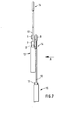
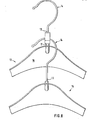
- an upper, conventional clothes hanger 12 is hung in the usual way on a horizontal clothes rail (cf. FIGS. 7, 8).
- the described fastening part according to FIGS. 1 to 3 or 4 to 6 is put on the lower straight section 13 of the clothes hanger hook 14, thus inserting the injection molded part with its slot 2 into the section 13 of the clothes hanger hook.
- this bears against the rearward bent end of the slot 2 and is held there in a positionally secure manner via the bend.
- At the entrance to the slot there may also be a constriction 9, so that the injection molded part must be inserted into the slot in a snap fit.
- section 13 is also seated in slot 2.
- a plastic part according to the invention can in turn be plugged onto this second coat hanger, and so on, until the existing room height with the staggered, tiered clothes is used. You can then start again with an upper coat hook, as described above, until the specified length of the clothes rail is also used.
- FIGS. 7 and 8 also show that, for the best possible use of space, the lower hanger 15 ends with its hook 14, which usually has a thickened end, at a short distance above the actual plastic part 16 of the upper hanger 12.
- the thickness of the fastening part is not greater than the thickness of this plastic part 16 plus the thickness of the wire thickness of the hanger hook.
- the back of the fastening part does not protrude beyond the back of the plastic part 16, as can be seen in particular from FIG. At the front, the fastening part protrudes only slightly beyond the wire thickness of the lower hanger hook.
- the fastening part sits on a cylindrical extension 17, also made of plastic, of the hanger, which extension serves to receive and anchor the hanger hook if the hanger has such an extension.
Landscapes
- Holders For Apparel And Elements Relating To Apparel (AREA)
Applications Claiming Priority (2)
| Application Number | Priority Date | Filing Date | Title |
|---|---|---|---|
| DE19838334310 DE8334310U1 (de) | 1983-11-30 | 1983-11-30 | Haengevorrichtung fuer kleiderbuegel |
| DE8334310U | 1983-11-30 |
Publications (2)
| Publication Number | Publication Date |
|---|---|
| EP0144653A2 true EP0144653A2 (fr) | 1985-06-19 |
| EP0144653A3 EP0144653A3 (fr) | 1986-02-05 |
Family
ID=6759366
Family Applications (1)
| Application Number | Title | Priority Date | Filing Date |
|---|---|---|---|
| EP84112587A Withdrawn EP0144653A3 (fr) | 1983-11-30 | 1984-10-18 | Dispositif d'accrochage pour cintres |
Country Status (2)
| Country | Link |
|---|---|
| EP (1) | EP0144653A3 (fr) |
| DE (1) | DE8334310U1 (fr) |
Cited By (7)
| Publication number | Priority date | Publication date | Assignee | Title |
|---|---|---|---|---|
| US4653678A (en) * | 1985-10-04 | 1987-03-31 | Batts, Inc. | Ganging hook for garment hangers |
| US5074445A (en) * | 1990-08-29 | 1991-12-24 | Chen Chia Sing | Garment hanger with swivel hook and ganging hook |
| GR900100215A (el) * | 1990-03-22 | 1992-06-30 | Mariettos Anastasios I | Μεθοδος και συνδετικα μεσα για την αλληλοσυνδεση κρεμαστρων ρουχων. |
| GB2383746A (en) * | 2001-12-21 | 2003-07-09 | Stewart Melville Colborne | A device for hanging garments on a chair |
| US6595354B1 (en) * | 2002-04-03 | 2003-07-22 | Tumi, Inc. | Luggage with low-profile hanger bracket |
| US7228962B2 (en) | 2004-12-15 | 2007-06-12 | Tumi, Inc. | Luggage with low-profile hanger bracket and harness |
| USD1107359S1 (en) * | 2023-03-03 | 2025-12-23 | Gleener Inc. | Fabric care device |
Families Citing this family (1)
| Publication number | Priority date | Publication date | Assignee | Title |
|---|---|---|---|---|
| DE29814985U1 (de) | 1998-08-24 | 1999-03-25 | Dudas, Axl Nikolaus, 15234 Frankfurt | Kleiderbügelstop |
Family Cites Families (3)
| Publication number | Priority date | Publication date | Assignee | Title |
|---|---|---|---|---|
| US2498400A (en) * | 1948-02-07 | 1950-02-21 | Lude Miriam A Du | Support for garment hangers |
| GB739207A (en) * | 1953-07-02 | 1955-10-26 | Twinco Ltd | Improvements in hangers or airers for lightweight garments |
| NL7408748A (nl) * | 1974-06-28 | 1975-12-30 | Hazenveld Industrie | Kleerhanger. |
-
1983
- 1983-11-30 DE DE19838334310 patent/DE8334310U1/de not_active Expired
-
1984
- 1984-10-18 EP EP84112587A patent/EP0144653A3/fr not_active Withdrawn
Cited By (7)
| Publication number | Priority date | Publication date | Assignee | Title |
|---|---|---|---|---|
| US4653678A (en) * | 1985-10-04 | 1987-03-31 | Batts, Inc. | Ganging hook for garment hangers |
| GR900100215A (el) * | 1990-03-22 | 1992-06-30 | Mariettos Anastasios I | Μεθοδος και συνδετικα μεσα για την αλληλοσυνδεση κρεμαστρων ρουχων. |
| US5074445A (en) * | 1990-08-29 | 1991-12-24 | Chen Chia Sing | Garment hanger with swivel hook and ganging hook |
| GB2383746A (en) * | 2001-12-21 | 2003-07-09 | Stewart Melville Colborne | A device for hanging garments on a chair |
| US6595354B1 (en) * | 2002-04-03 | 2003-07-22 | Tumi, Inc. | Luggage with low-profile hanger bracket |
| US7228962B2 (en) | 2004-12-15 | 2007-06-12 | Tumi, Inc. | Luggage with low-profile hanger bracket and harness |
| USD1107359S1 (en) * | 2023-03-03 | 2025-12-23 | Gleener Inc. | Fabric care device |
Also Published As
| Publication number | Publication date |
|---|---|
| EP0144653A3 (fr) | 1986-02-05 |
| DE8334310U1 (de) | 1984-03-01 |
Similar Documents
| Publication | Publication Date | Title |
|---|---|---|
| DE69509314T2 (de) | Kleiderbügel | |
| DE60003891T2 (de) | Befestigungsvorrichtung mit einem an einer wand abgehängten stab | |
| DE2216777C3 (de) | Klemmleiste zum Aufhängen von blatt- bzw. bogenartigen Materialstücken | |
| DE3214727A1 (de) | Verbindungsvorrichtung | |
| EP0362968A1 (fr) | Présentoir mural | |
| DE3410974A1 (de) | Deckenbefestigung fuer dekorationselemente und dergleichen | |
| DE2446804A1 (de) | Schublade | |
| DE60112105T2 (de) | Aufhängesystem | |
| EP0144653A2 (fr) | Dispositif d'accrochage pour cintres | |
| EP0098455B1 (fr) | Montant d'étagères pour un mur de séparation ou un panneautage mural | |
| DE2648467A1 (de) | Befestigungsklammer fuer die befestigung von glatten bolzen an plattenartigen bauteilen | |
| DE2003366B2 (de) | Vorhangaufhängevorrichtung | |
| DE2948353C2 (de) | Vorrichtung zum Halten von Gegenständen | |
| DE19600175C1 (de) | Haltesystem für Utensilien | |
| EP0088070B1 (fr) | Crampon | |
| DE29614919U1 (de) | Kleiderbügel | |
| DE2041642B2 (de) | Unterdecke mit mittels Befestigungsbügeln an Tragschienen befestigten Deckenelementen | |
| DE1779220C3 (de) | Ausziehbarer Fachbodenträger | |
| DE8405471U1 (de) | Lochplattenhaken | |
| DE2840880A1 (de) | Aufhaengevorrichtung fuer kleidungsstuecke, insbesondere fuer zechen, badeanstalten o.dgl. | |
| DE29704787U1 (de) | Einsetzbarer Träger für Verkaufsgestelle | |
| DE20103307U1 (de) | Prospekthalter | |
| DD255074A1 (de) | Kippvorrichtung fuer magazinbeuten | |
| DE7038253U (de) | Aus Schienen und Konsolen bestehende Aufhange bzw Tragevorrichtung fur Bucher bretter u dgl | |
| DE3347892A1 (de) | Regal |
Legal Events
| Date | Code | Title | Description |
|---|---|---|---|
| PUAI | Public reference made under article 153(3) epc to a published international application that has entered the european phase |
Free format text: ORIGINAL CODE: 0009012 |
|
| AK | Designated contracting states |
Designated state(s): AT BE CH DE FR GB IT LI NL SE |
|
| PUAL | Search report despatched |
Free format text: ORIGINAL CODE: 0009013 |
|
| AK | Designated contracting states |
Designated state(s): AT BE CH DE FR GB IT LI NL SE |
|
| STAA | Information on the status of an ep patent application or granted ep patent |
Free format text: STATUS: THE APPLICATION IS DEEMED TO BE WITHDRAWN |
|
| 18D | Application deemed to be withdrawn |
Effective date: 19861006 |
|
| RIN1 | Information on inventor provided before grant (corrected) |
Inventor name: KOTOWSKI, KLEMENS P. |