EP0144854A2 - Méthode de fabrication d'un fusible miniature ainsi que fusible miniature - Google Patents
Méthode de fabrication d'un fusible miniature ainsi que fusible miniature Download PDFInfo
- Publication number
- EP0144854A2 EP0144854A2 EP84114010A EP84114010A EP0144854A2 EP 0144854 A2 EP0144854 A2 EP 0144854A2 EP 84114010 A EP84114010 A EP 84114010A EP 84114010 A EP84114010 A EP 84114010A EP 0144854 A2 EP0144854 A2 EP 0144854A2
- Authority
- EP
- European Patent Office
- Prior art keywords
- housing
- electrodes
- intermediate carrier
- fuse
- fusible conductor
- Prior art date
- Legal status (The legal status is an assumption and is not a legal conclusion. Google has not performed a legal analysis and makes no representation as to the accuracy of the status listed.)
- Withdrawn
Links
Images

Classifications
-
- H—ELECTRICITY
- H01—ELECTRIC ELEMENTS
- H01H—ELECTRIC SWITCHES; RELAYS; SELECTORS; EMERGENCY PROTECTIVE DEVICES
- H01H69/00—Apparatus or processes for the manufacture of emergency protective devices
- H01H69/02—Manufacture of fuses
-
- H—ELECTRICITY
- H01—ELECTRIC ELEMENTS
- H01H—ELECTRIC SWITCHES; RELAYS; SELECTORS; EMERGENCY PROTECTIVE DEVICES
- H01H85/00—Protective devices in which the current flows through a part of fusible material and this current is interrupted by displacement of the fusible material when this current becomes excessive
- H01H85/02—Details
- H01H85/04—Fuses, i.e. expendable parts of the protective device, e.g. cartridges
- H01H85/041—Fuses, i.e. expendable parts of the protective device, e.g. cartridges characterised by the type
- H01H85/0411—Miniature fuses
-
- Y—GENERAL TAGGING OF NEW TECHNOLOGICAL DEVELOPMENTS; GENERAL TAGGING OF CROSS-SECTIONAL TECHNOLOGIES SPANNING OVER SEVERAL SECTIONS OF THE IPC; TECHNICAL SUBJECTS COVERED BY FORMER USPC CROSS-REFERENCE ART COLLECTIONS [XRACs] AND DIGESTS
- Y10—TECHNICAL SUBJECTS COVERED BY FORMER USPC
- Y10T—TECHNICAL SUBJECTS COVERED BY FORMER US CLASSIFICATION
- Y10T29/00—Metal working
- Y10T29/49—Method of mechanical manufacture
- Y10T29/49002—Electrical device making
- Y10T29/49107—Fuse making
-
- Y—GENERAL TAGGING OF NEW TECHNOLOGICAL DEVELOPMENTS; GENERAL TAGGING OF CROSS-SECTIONAL TECHNOLOGIES SPANNING OVER SEVERAL SECTIONS OF THE IPC; TECHNICAL SUBJECTS COVERED BY FORMER USPC CROSS-REFERENCE ART COLLECTIONS [XRACs] AND DIGESTS
- Y10—TECHNICAL SUBJECTS COVERED BY FORMER USPC
- Y10T—TECHNICAL SUBJECTS COVERED BY FORMER US CLASSIFICATION
- Y10T29/00—Metal working
- Y10T29/49—Method of mechanical manufacture
- Y10T29/49799—Providing transitory integral holding or handling portion
Definitions
- the invention relates to a method for producing a miniature fuse in which, after fixing the distance between two connecting electrodes, a fusible conductor is fastened between them in an electrically conductive manner and then an initially two-part housing surrounding the electrodes and the fusible conductor is closed.
- a miniature fuse which consists of a housing composed of two halves with electrodes held therein, on which there are connecting wire ends on one side and a fuse element is fastened on the other side.
- the previously known miniature fuses which are also called pico fuses, can be viewed as a miniature fuse of normal size, for example 20 mm in length; for example, they consist of a ceramic tube, caps are glued to both sides, to which the fusible conductor located inside the ceramic tube and the connecting wires are soldered.
- the manufacture of such a fuse which is only approx. 7 mm long and approx. 2.4 mm thick, is still largely carried out manually, so that comparatively high production costs are present.
- the reason for the predominantly manual production lies in the difficult handling of the Fusible wire, which in extreme cases has a diameter of only 8 ⁇ m.
- the housing is essentially smooth on the inside, that the spaced electrodes are pre-attached in one housing part and that after the fuse element has been attached, the housing is closed with the electrodes permanently attached to the inner surface.
- the housing is essentially on the inside Lich smooth surface is formed that the fusible conductor is fastened between the spaced electrodes and that the electrodes are placed together with the fusible conductor in one housing part and then the second housing part is laid to fix the electrodes and the fusible conductor and to close the housing.
- the housing is of tubular design and is essentially smooth on the inside and that the electrodes close the end faces of the housing in the manner of a stopper.
- the housing be tubular and consist of a substantially smooth surface on its inner surface and closed on both ends except for a passage for the respective contact and on the inside with at least one transverse to the longitudinal axis in the front Partition plane, possibly extending to the outside of the housing, and connected to the contact there or provided with one-piece arm.
- micro-fuse manufactured according to the above-mentioned methods and the one protected is each externally presented as a cylindrical body, which does not carry any thickening due to caps or the like at its ends, but rather its end faces either in the manner of a; Plug through the electrodes or through end walls, each with a passage for the electrodes, are closed. In this way, there are excellent conditions for marking printing, without the need for a shrink tube or a powder coating.
- the defined diameter limit can therefore benefit fully from the size of the housing, which indirectly facilitates production.
- the two housing parts are designed as tube halves, they can be cut to length continuously, that is to say they can be produced in a manner that is hard to beat in terms of simplicity.
- a welding lip can be formed on one narrow side, the two tube halves then being placed in opposite directions when the housing is closed, so that a welding lip meets a smooth narrow side without a welding lip.
- the pre-attachment or the final attachment of the electrodes within the housing halves and the cohesion of the housing itself can be carried out with the aid of an adhesive, or a connection is brought about by heating, in which case the housing material must be a thermoplastic.
- the housing material must be a thermoplastic.
- ultrasound heads, radiators or other heat sources can be used, which are usually used when gluing and embedding parts in thermoplastics.
- the other surface can be roughened, for example sandblasted or etched.
- the easy penetration of the electrodes into the inner surface of the housing means that the fuse element is not on the outside is soldered to the periphery of the electrodes, but more in the center so that it is not sheared off when the housing is closed.
- a sufficiently central attachment of the fuse element is obtained if the sides of the electrodes facing the fuse element are provided with a notch, which possibly extends to the center of the electrode and enables an approximately central soldering of the fuse element to each electrode.
- a very essential development according to the invention of the method referred to above as the second proposal is that an intermediate carrier is formed for the electrodes to be kept at a distance and for attaching the fuse element to the fuse carrier, on which the fuse element spans a loop, frame or bow-shaped extension is attached in an electrically conductive manner with both ends, whereupon the intermediate carrier including fuse element and electrodes formed or fastened on the intermediate carrier is arranged between the housing halves and the housing is closed.
- the intermediate carrier consequently forms a "lost" device with which the electrodes and the fuse element are already connected to one another and are arranged in the intended mutual position between the housing halves before they are permanently attached to one another.
- the method according to the invention is further simplified as a result.
- each wing projects approximately parallel to the parting plane from the housing halves, which are cut off from the housing after the housing has been closed with the parts of the intermediate carrier lying between the wings and outside the housing and no longer used.
- These wings are formed in the manufacture of the thermoplastic housing halves, and within the scope of the invention they serve to center the housing halves and to accommodate the side Lich protruding loop, frame or bow-shaped part of the intermediate carrier.
- a metal strip is formed in the form of a conductor, on the rungs of which a fusible conductor fader running transversely over this is attached in an electrically conductive manner, whereupon the intermediate carriers are separated from the metal strip along the rungs and provided with the electrodes.
- a fusible conductor fader running transversely over this is attached in an electrically conductive manner, whereupon the intermediate carriers are separated from the metal strip along the rungs and provided with the electrodes.
- rectangular frame-shaped intermediate carriers result.
- the fusible conductor thread can firstly be attached very simply and secondly without any noteworthy waste of expensive fusible conductor material to the initially ladder-shaped metal strip, from which the intermediate carriers are then separated individually.
- the intermediate carrier is ready to be inserted into the housing halves.
- the intermediate carrier according to the invention can be formed from a piece of metal wire, to which a bow-shaped extension is given, at the inner corners of which the fuse element is attached in an electrically conductive manner, approximately in continuation of the outer metal wire ends. Due to this loop-shaped or bow-shaped shape of the intermediate carrier, the electrodes are automatically formed on the intermediate carrier. It is therefore only necessary to attach the fuse element to the inner corners of the bow-shaped extension so that it spans the extension freely, whereupon the intermediate carrier is ready for insertion between the housing halves.
- a mixed form or combination of the two aforementioned methods for producing intermediate carriers is provided.
- This form of the method according to the invention is characterized in that after the attachment of a fusible conductor thread on an essentially conductor Shaped metal strip of this intermediate carrier with a second, but essentially bow-shaped metal wire intermediate carrier, the ends of which form the electrodes, is connected to one another in a electrically conductive manner to form a combined intermediate carrier, preferably welded, the first two intermediate carriers being placed one on top of the other.
- the advantages of the first two intermediate support forms are combined.
- the intermediate carrier can be completely or partially flattened.
- the flattening provides more stability, the round wire shape allows easier centering of the intermediate carrier between the housing halves. You can also help yourself with partial flattening.
- the housing halves are each closed on the front side except for a recess for the passage of the contact.
- Semicircular end walls are used for this, which are already standardized during the manufacture of the housing halves.
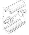
- FIG. 1 A lower housing half 1, which consists for example of a high-strength thermoplastic, is ready to receive the inner components. These include two electrodes 3 and a fusible conductor 7, which are already combined to form a unit. After the reduction in the lower housing half 1 by means of a device not illustrated in detail here (a "lost" device ig follows from the embodiments shown in F. 8-16), the second housing half 2 on the lower Half of housing 1 placed and heated under gentle pressure along the dividing lines, for example by ultrasound. This completes the production of a miniature fuse according to the invention.
- a "lost" device ig follows from the embodiments shown in F. 8-16
- the electrodes 3 are specially designed for a firm bond with the housing halves 1 and 2.
- the electrode formed by thickening at the end of a connecting wire 4 carries a circumferential V-groove 5 which produces two sharp-edged edges which are slightly larger in diameter than the inside diameter of the housing formed on the halves 1 and 2. In this way, when the housing is closed as a result of the heating of the corresponding housing sections, the sharp edges are slightly recessed into the inner surfaces of the housing halves 1 and 2, so that a very stable form-fit is obtained, which gives the miniature fuse overall good strength properties.
- the fusible conductor 7 must not be soldered to the outer edge of the electrodes 3 - here it shears when the housing halves 1 and 2 are closed, but further to the center of the electrodes 3, which is achieved in the exemplary embodiment shown with the aid of notches 6, which allow a sufficiently central attachment of the fuse element 7.
- the fuse element 7 For attaching the fuse element 7 to the electrodes 3, e.g. 6 Lötpaste.stricht in the notches and pressed the fuse element 7 adhering into the paste. With the help of an external heat source, the solder paste is melted, as a result of which the fusible conductor 7 is soldered to the electrodes 3.
- each housing half can of course also be smooth if, for example, the intention is to glue the housing parts 1 and 2 together; in this case it is also advisable to glue the electrodes 3 into the housing.
- an adhesive is used, almost any material can be used for the housing halves 1 and 2, in particular, for example, also a ceramic material or glass fiber-reinforced tube halves, which have also proven themselves as a fuse housing.
- FIGS. 2 and 3 which form the miniature fuse has after the housing halves 1 and 2 have been closed. While in the exemplary embodiment according to FIG. 2 the fusible conductor 7 is soldered between the electrodes 3 within one and the same plane and the electrodes have subsequently not been rotated relative to one another, FIG. 3 shows an exemplary embodiment with electrodes rotated by 180 °, which leads to this that the fuse element 7 runs slightly diagonally within the housing halves. It can be clearly seen from both figures that the slight penetration of the sharp-edged electrodes into the inner surface of the housing halves 1 and 2 does not impair the fusible conductor 7, which is sufficiently centrally soldered to the electrodes 3.
- FIGS. 4 and 7 show the electrode 3 used in the exemplary embodiments described above shown. It can be clearly seen that the notch 6 is only present in the section of the electrode 3 facing the fusible conductor 7, so that there is a self-contained, circumferential sharp edge towards the connecting wire 4, which edge defines the interior of the housing halves 1 and 2 completes completely.
- the existing between the two sections of the electrode 3 V-groove 5 allows the sinking of a tool down to the bottom of the notch 6, so that the 8 ⁇ m thin fuse element 7 can be brought to the electrodes 3 without difficulty and soldered there.
- FIG. 5 shows an exemplary embodiment for an electrode 3 'in which the fusible conductor 7 is soldered to the end face of the electrode 3'.
- the exemplary embodiment of an electrode 3 "shown in FIG. 6 is particularly suitable for gluing into the housing and thus also for housing halves which are glued together as intended. Again, the fuse element 7 can be soldered to the end face of the electrode 3", so that there is no danger the damage is in the vicinity of the housing wall.
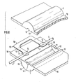
- FIGS. 8-16 are essentially different in their differences from the embodiments of the miniature fuse as described above and illustrated in the drawings and of the production methods.
- the two housing halves 1, 2 have wings 10 extending laterally from their opening, which are also molded during the production of the housing halves 1, 2.
- semicircular end walls 11 with likewise semicircular passages 12 for the electrodes 3. whose connecting wires 4 are provided.
- the electrodes 3 1 like the connecting wires 4, are formed on a bow-shaped intermediate carrier 13, and the fuse element 7 spans the bow opening with fastening points by solder 14. In this fully preassembled state, the intermediate carrier 13 is brought between the two housing halves 1, 2, whereupon the two housing halves including their wings 10 are connected together in the manner already described above.
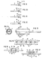
- FIGS. 9-12 There are a number of possibilities for the design of the intermediate carrier 13, which are shown in FIGS. 9-12.
- the cross section of the intermediate carrier 13 can be left round throughout (FIG. 9). But you can also flatten the actual bracket part 16 'to give it more stability, to achieve a larger and essentially flat surface for the fastening points by solder 14 and to ensure easier insertion of the intermediate carrier 13 also in the area of the wings 10 , while the round cross-section of the connecting wire 4 or the appropriately designed start of the electrodes 3 1, which is suitable for centering in the longitudinal direction of the housing, is still retained (FIG. 10).
- a completely flattened version of the intermediate carrier 13 according to FIG. 12 is of particular stability. In this case, a passage opening on the end walls 11 adapted to this cross section must be provided for the purpose of clear fixation.
- 15 and 16 show a modified embodiment of the bracket.
- a ladder-shaped metal strip 18 is punched out, over which, as shown, a fusible conductor wire 19 is guided and fixed to the rungs 21 of the metal strip 18 by means of solder 20.
- the intermediate carriers 13 ' are continuously separated from the metal strip 18 along the rungs 21 or the lines 22 shown in broken lines.
- the intermediate carrier 13 ′ is fastened between the housing halves 1, 2 provided with wings 10 in the same way as the previously described intermediate carrier 13 (see FIG. 8). .
- the third embodiment of an intermediate carrier 13 ′′ shown in FIG. 17 is a mixed form, which consists of an intermediate carrier 13 and an intermediate carrier 13 ′ placed thereon and preferably electrically welded and fastened thereon.
- the fusible conductor 7 has already been fastened in the manner described above before the metal strip 18 is divided, and the connecting wires or contacts 4 extend on both sides after the intermediate carrier 13 has been formed from a piece of metal wire.
- the arms 17 remain in the miniature fuse, they extend at each of the two fuse ends approximately radially on both sides, always in duplicate on one side, namely as a piece of metal wire with a piece of sheet metal attached to it.
- This embodiment has a particular stability with good centerability, and it is possible to avoid soldering the connecting wires or electrodes 4, as shown in FIG. 16, to the side.
Landscapes
- Engineering & Computer Science (AREA)
- Manufacturing & Machinery (AREA)
- Fuses (AREA)
Applications Claiming Priority (2)
| Application Number | Priority Date | Filing Date | Title |
|---|---|---|---|
| DE19833342302 DE3342302A1 (de) | 1983-11-23 | 1983-11-23 | Verfahren zur herstellung einer kleinstsicherung sowie kleinstsicherung |
| DE3342302 | 1983-11-23 |
Publications (2)
| Publication Number | Publication Date |
|---|---|
| EP0144854A2 true EP0144854A2 (fr) | 1985-06-19 |
| EP0144854A3 EP0144854A3 (fr) | 1987-04-29 |
Family
ID=6215029
Family Applications (1)
| Application Number | Title | Priority Date | Filing Date |
|---|---|---|---|
| EP84114010A Withdrawn EP0144854A3 (fr) | 1983-11-23 | 1984-11-20 | Méthode de fabrication d'un fusible miniature ainsi que fusible miniature |
Country Status (3)
| Country | Link |
|---|---|
| US (1) | US4851805A (fr) |
| EP (1) | EP0144854A3 (fr) |
| DE (1) | DE3342302A1 (fr) |
Cited By (4)
| Publication number | Priority date | Publication date | Assignee | Title |
|---|---|---|---|---|
| DE9005916U1 (de) * | 1990-05-25 | 1991-09-26 | Doduco GmbH + Co Dr. Eugen Dürrwächter i.K., 75181 Pforzheim | Elektrische Sicherung zum Einbau in Stromversorgungskabel in Kraftfahrzeugen |
| EP0621621A3 (en) * | 1993-04-23 | 1995-11-08 | Gould Electronics Inc | Current limiting fuses. |
| CN1072054C (zh) * | 1996-06-07 | 2001-10-03 | 曼内斯曼股份公司 | 用于薄钢带浇铸装置的浇铸喷嘴 |
| CN111463089A (zh) * | 2019-01-21 | 2020-07-28 | 力特保险丝公司 | 熔断器和形成熔断器的方法 |
Families Citing this family (14)
| Publication number | Priority date | Publication date | Assignee | Title |
|---|---|---|---|---|
| US4996509A (en) * | 1989-08-25 | 1991-02-26 | Elliot Bernstein | Molded capless fuse |
| JP3820143B2 (ja) * | 2001-02-16 | 2006-09-13 | エス・オー・シー株式会社 | 表面実装型小型ヒューズ |
| DE50207930D1 (de) * | 2001-03-02 | 2006-10-05 | Wickmann Werke Gmbh | Sicherungsbauelement |
| US7436283B2 (en) * | 2003-11-20 | 2008-10-14 | Cooper Technologies Company | Mechanical reinforcement structure for fuses |
| JP4361095B2 (ja) * | 2004-02-21 | 2009-11-11 | ビックマン−ベルケ ゲーエムベーハー | ヒューズエレメント用絶縁中間コイルを備えるコイル状可溶導体 |
| US20060119465A1 (en) * | 2004-12-03 | 2006-06-08 | Dietsch G T | Fuse with expanding solder |
| DE502005001781D1 (de) * | 2005-06-02 | 2007-12-06 | Wickmann Werke Gmbh | Wickelschmelzleiter für ein Schmelzsicherungsbauelement mit Kunststoffversiegelung |
| US20080100412A1 (en) * | 2006-10-06 | 2008-05-01 | Han-Ming Lee | Insulated shockproof fuse |
| CN101282056B (zh) * | 2007-04-04 | 2014-08-06 | 松下电器产业株式会社 | 无刷直流马达温度保护装置 |
| US9117615B2 (en) | 2010-05-17 | 2015-08-25 | Littlefuse, Inc. | Double wound fusible element and associated fuse |
| JP6426056B2 (ja) * | 2015-06-08 | 2018-11-21 | 豊田鉄工株式会社 | ヒューズ |
| CN108091528B (zh) * | 2017-11-29 | 2020-02-07 | 国网浙江省电力公司丽水供电公司 | 一种弹性推压式高压熔断器管座 |
| US11317661B2 (en) * | 2019-01-04 | 2022-05-03 | Matthew Winningham | Arm warming device |
| US11721511B2 (en) * | 2022-01-06 | 2023-08-08 | Littelfuse, Inc. | Fuse terminal design |
Family Cites Families (9)
| Publication number | Priority date | Publication date | Assignee | Title |
|---|---|---|---|---|
| US2759065A (en) * | 1955-01-10 | 1956-08-14 | Moeller Arthur Edward | Fuse holder |
| GB971709A (en) * | 1962-05-16 | 1964-10-07 | Microfuses Ltd | Improvements in or relating to fuses |
| US3355532A (en) * | 1963-01-15 | 1967-11-28 | Ltv Electrosystems Inc | Molded resistor and method of fabricating same |
| GB1577684A (en) * | 1978-03-28 | 1980-10-29 | Welwyn Electric Ltd | Fuse array |
| DE3033323A1 (de) * | 1979-09-11 | 1981-03-26 | Rohm Co. Ltd., Kyoto | Schutzvorrichtung fuer eine halbleitervorrichtung |
| WO1981001627A1 (fr) * | 1979-12-03 | 1981-06-11 | Beswick Kenneth E Ltd | Procede de fabrication de fusibles electriques enfichables et fusibles produits par ce procede |
| DE3044040A1 (de) * | 1980-11-22 | 1982-07-15 | Wilhelm Pudenz KG, 2833 Dünsen | Stecksicherung |
| US4326185A (en) * | 1981-04-27 | 1982-04-20 | San-O Industrial Company, Ltd. | Electrical fuse with semi-cylindrical casings |
| JPS5921500Y2 (ja) * | 1982-03-19 | 1984-06-25 | 三王株式会社 | リ−ド付き超小型ヒュ−ズ |
-
1983
- 1983-11-23 DE DE19833342302 patent/DE3342302A1/de not_active Withdrawn
-
1984
- 1984-11-20 EP EP84114010A patent/EP0144854A3/fr not_active Withdrawn
- 1984-11-23 US US06/674,075 patent/US4851805A/en not_active Expired - Fee Related
Cited By (8)
| Publication number | Priority date | Publication date | Assignee | Title |
|---|---|---|---|---|
| DE9005916U1 (de) * | 1990-05-25 | 1991-09-26 | Doduco GmbH + Co Dr. Eugen Dürrwächter i.K., 75181 Pforzheim | Elektrische Sicherung zum Einbau in Stromversorgungskabel in Kraftfahrzeugen |
| DE4116983A1 (de) * | 1990-05-25 | 1991-11-28 | Duerrwaechter E Dr Doduco | Elektrische sicherung zum einbau in stromversorgungskabel in kraftfahrzeugen |
| EP0621621A3 (en) * | 1993-04-23 | 1995-11-08 | Gould Electronics Inc | Current limiting fuses. |
| CN1072054C (zh) * | 1996-06-07 | 2001-10-03 | 曼内斯曼股份公司 | 用于薄钢带浇铸装置的浇铸喷嘴 |
| CN111463089A (zh) * | 2019-01-21 | 2020-07-28 | 力特保险丝公司 | 熔断器和形成熔断器的方法 |
| EP3690919A1 (fr) * | 2019-01-21 | 2020-08-05 | Littelfuse, Inc. | Fusible |
| US11101093B2 (en) | 2019-01-21 | 2021-08-24 | Littelfuse, Inc. | Fuses and methods of forming fuses |
| US11521818B2 (en) | 2019-01-21 | 2022-12-06 | Littelfuse, Inc. | Fuses and methods of forming fuses |
Also Published As
| Publication number | Publication date |
|---|---|
| DE3342302A1 (de) | 1985-05-30 |
| EP0144854A3 (fr) | 1987-04-29 |
| US4851805A (en) | 1989-07-25 |
Similar Documents
| Publication | Publication Date | Title |
|---|---|---|
| EP0144854A2 (fr) | Méthode de fabrication d'un fusible miniature ainsi que fusible miniature | |
| DE4419055C2 (de) | Chip-Schmelzsicherung | |
| DE2203435C2 (de) | Elektrisches Verbinderelement | |
| CH669478A5 (fr) | ||
| DE2641461B2 (de) | Drahtklemme | |
| DE2444892C3 (de) | Verfahren zur Herstellung von streifenförmigen Anschlußelementen | |
| DE2502214C2 (de) | Verfahren zur Herstellung von laminierten Sammelschienen | |
| DE3221290A1 (de) | Elektrische lampe mit einem huelsenfoermigen sockel | |
| EP0536523B1 (fr) | Borne de connexion | |
| DE69405333T2 (de) | Lampen-Stromzuführungsvorrichtung mit geformter Folie | |
| DE3237159C1 (de) | Kontaktelement fuer elektrische Steckverbindungen und Verfahren zur Herstellung von derartigen Kontaktelementen | |
| DE3304263A1 (de) | Glasschmelzsicherungen sowie verfahren zu ihrer herstellung | |
| EP0655169B2 (fr) | Porte-balai pour moteurs electriques | |
| EP1318565B1 (fr) | Antenne, en particuliere antenne de radiotelephonie mobile, avec moyen de centrage pendant la fabrication | |
| DE2137990B2 (de) | Schmelzsicherung | |
| DE4425151A1 (de) | Fokussierbare Lampenkapsel in einem kittfreien Sockel | |
| DE102016125897B4 (de) | Lötfähiges elektrisches Anschlusselement | |
| DE69323595T2 (de) | Innerer Teil eines Lampengehäuses | |
| DE3610086A1 (de) | Endstueck fuer einen elektrischen leiter und verfahren zur herstellung desselben | |
| DE8911461U1 (de) | Anker für einen Elektromotor | |
| DE102012223082A1 (de) | Kontaktelement und Verfahren zur Herstellung eines Kontaktelements | |
| DE68917415T2 (de) | Anschluss eines Kabels an eine Elektrode einer Folie insbesondere Heizfolie, mittels eindringendem Kabelschuh, Kabelschuh für solchen Anschluss und Leiste bestehend aus einer Vielzahl zusammenhängender eindringender Kabelschuhe. | |
| DE1962269B2 (de) | Sicherungseinsatz mit einem stirnseitig durch Endplatten verschlossenen rohrförmigen Isolierkörper | |
| DE60124465T2 (de) | Entladungslampe | |
| DE2855058A1 (de) | Anoden- und kathodenleitungsdrahtaufbau fuer festkoerperelektrolytkondensatoren |
Legal Events
| Date | Code | Title | Description |
|---|---|---|---|
| PUAI | Public reference made under article 153(3) epc to a published international application that has entered the european phase |
Free format text: ORIGINAL CODE: 0009012 |
|
| AK | Designated contracting states |
Designated state(s): AT BE CH DE FR GB IT LI LU NL SE |
|
| PUAL | Search report despatched |
Free format text: ORIGINAL CODE: 0009013 |
|
| AK | Designated contracting states |
Kind code of ref document: A3 Designated state(s): AT BE CH DE FR GB IT LI LU NL SE |
|
| 17P | Request for examination filed |
Effective date: 19870526 |
|
| 17Q | First examination report despatched |
Effective date: 19880816 |
|
| STAA | Information on the status of an ep patent application or granted ep patent |
Free format text: STATUS: THE APPLICATION IS DEEMED TO BE WITHDRAWN |
|
| 18D | Application deemed to be withdrawn |
Effective date: 19890531 |
|
| RIN1 | Information on inventor provided before grant (corrected) |
Inventor name: POERSCHKE, KARL, DR.-ING. |