EP0144869A2 - Reflektionsspektrometer mit streifender Inzidenz - Google Patents
Reflektionsspektrometer mit streifender Inzidenz Download PDFInfo
- Publication number
- EP0144869A2 EP0144869A2 EP84114155A EP84114155A EP0144869A2 EP 0144869 A2 EP0144869 A2 EP 0144869A2 EP 84114155 A EP84114155 A EP 84114155A EP 84114155 A EP84114155 A EP 84114155A EP 0144869 A2 EP0144869 A2 EP 0144869A2
- Authority
- EP
- European Patent Office
- Prior art keywords
- light
- sample
- incident light
- grazing incidence
- sample surface
- Prior art date
- Legal status (The legal status is an assumption and is not a legal conclusion. Google has not performed a legal analysis and makes no representation as to the accuracy of the status listed.)
- Granted
Links
Images

Classifications
-
- G—PHYSICS
- G01—MEASURING; TESTING
- G01N—INVESTIGATING OR ANALYSING MATERIALS BY DETERMINING THEIR CHEMICAL OR PHYSICAL PROPERTIES
- G01N21/00—Investigating or analysing materials by the use of optical means, i.e. using sub-millimetre waves, infrared, visible or ultraviolet light
-
- G—PHYSICS
- G01—MEASURING; TESTING
- G01N—INVESTIGATING OR ANALYSING MATERIALS BY DETERMINING THEIR CHEMICAL OR PHYSICAL PROPERTIES
- G01N21/00—Investigating or analysing materials by the use of optical means, i.e. using sub-millimetre waves, infrared, visible or ultraviolet light
- G01N21/17—Systems in which incident light is modified in accordance with the properties of the material investigated
- G01N21/55—Specular reflectivity
-
- G—PHYSICS
- G01—MEASURING; TESTING
- G01J—MEASUREMENT OF INTENSITY, VELOCITY, SPECTRAL CONTENT, POLARISATION, PHASE OR PULSE CHARACTERISTICS OF INFRARED, VISIBLE OR ULTRAVIOLET LIGHT; COLORIMETRY; RADIATION PYROMETRY
- G01J3/00—Spectrometry; Spectrophotometry; Monochromators; Measuring colours
- G01J3/28—Investigating the spectrum
- G01J3/42—Absorption spectrometry; Double beam spectrometry; Flicker spectrometry; Reflection spectrometry
-
- G—PHYSICS
- G01—MEASURING; TESTING
- G01N—INVESTIGATING OR ANALYSING MATERIALS BY DETERMINING THEIR CHEMICAL OR PHYSICAL PROPERTIES
- G01N21/00—Investigating or analysing materials by the use of optical means, i.e. using sub-millimetre waves, infrared, visible or ultraviolet light
- G01N21/17—Systems in which incident light is modified in accordance with the properties of the material investigated
- G01N21/21—Polarisation-affecting properties
Definitions
- the present invention relates to a grazing incidence reflection spectrometer which causes light to incide obliquely to a sample surface and detects light reflected therefrom, whereby the electronic absorption spectrum of a chemical species adsorbed to the sample surface is measured at high sensitivity.
- sample shall indicate a substrate which includes a smooth surface having no chemical species adsorbed thereto
- chemical species adsorbed to the sample surface shall signify a chemical species which has an interaction with the sample surface including ordinary physical adsorption or chemical adsorption (the same applies hereinbelow).
- a grazing incidence reflection spectrometer wherein light is caused to incide on a surface of a sample, and an intensity of light reflected from the sample surface is detected, thereby to measure an electronic absorption spectrum of a material adsorbed to the sample surface, is so constructed that the incident light is visible light or ultraviolet light, and that said incident light has a predetermined glancing angle to the sample surface.
- the electronic absorption spectrum of a chemical species adsorbed to the sample surface can be measured at high sensitivity.
- the sample is not restricted to an opaque material, but it may be a transparent material as well.
- the adsorbed chemical species is a molecule or an atom, the electronic absorption spectrum is permitted to be measured at high sensitivity.
- the mechanism by which light in the visible and ultraviolet regions is absorbed into a material can be apprehended as a process in which an electron within the material undergoes transition to a higher energy state owing to the energy of the light. Accordingly, the absorption spectrum of the light in the visible and ultraviolet regions is called the "electronic absorption spectrum".
- the electronic absorption spectrum of a chemical species adsorbed to the surface of a sample can be obtained by causing the light of the visible and ultraviolet regions to incide on the surface of the sample and measuring the intensity of light reflected from the sample surface. It has also been acknowledged that, whether the chemical species adsorbed to the sample surface is an atom or a molecule in this case, the electronic absorption spectrum thereof can be measured. However, the electronic absorption spectrum mentioned above has the drawback of a very low measurement sensitivity though it has been acknowledged to be, in principle, measurable.
- a conventional method of absorption measurement in which the intensity ratio of transmitted light to incident light is measured does not apply to the measurement of the electronic absorption spectrum of the visible light or ultraviolet light for the chemical species adsorbed to the sample surface, because a sufficient intensity of the transmitted light is not attained due to the absorption in the sample.
- a transparent material such as glass
- the total number of the adsorbed chemical species distributed in two dimensions is slight in an optical path, and hence, the application of the conventional method of absorption measurement is difficult in point of the detection sensitivity.
- the drawback is therefore solved by defining a glancing angle so that the reflectivity of the incident light from the sample may come sufficiently close to 1 (one), and then measuring the electronic absorption spectrum on the basis of the reflected light.
- the intensity of reflected light 3 relative to the intensity of light 2 entering a flat sample 1 whose surface has no chemical species adsorbed thereto, depends upon the real part and imaginary part of the complex refractive index of the sample 1, an angle 9 defined between the sample 1 and the incident light 2, and the direction of polarization of the incident light 2 with respect to a plane 5 containing the incident light 2 and the reflected light 3.
- the angle 9 shall be termed the "glancing angle ⁇ ", and the plane 5 the "plane of incidence 5". Shown in Figs.
- FIG. 2 and 3 are examples of results obtained by calculating the dependence of the relative reflected light intensity on the glancing angle 8 as to a case where the incident light 2 in a direction 6 perpendicular to the plane of incidence 5 and a case where it is polarized in a direction 7 parallel thereto.
- the real part of a complex refractive index is set at 3.46, and the imaginary part at 3.25.
- the real part of a complex refractive index is set at 1.52, and the imaginary part at 0.
- the complex refractive index in the case of Fig. 2 corresponds substantially to the value of tungsten for the visible light, and that in the case-of Fig. 3 to the value of glass.
- FIG. 2 and a curve 9 in Fig. 3 are of the case where the incident light 2 in Fig. 1 is polarized in the direction 6 perpendicular to the plane of incidence 5.
- a curve 10 in Fig. 2 and a curve 11 in Fig. 3 are of the case where the incident light 2 in Fig. 1 is polarized in the direction 7 parallel to the plane of incidence 5.
- Figs. 2 and 3 when the incident light 2 in Fig. 1 polarized in the direction 6 perpendicular to the plane of incidence 5 is used, relative reflected light intensities close to 1 (one) can be attained over an extensive range of glancing angles 9. In order to actually verify this, experiments were conducted on the samples 1 of various materials.
- the glancing angle ⁇ when the glancing angle ⁇ is set within 5 °, 90 % or'more of the incident light 2 is reflected from the sample 1, so the loss of the light attributed to the sample 1 itself is negligible in practical use.
- the area of the light irradiation part 12 of the sample 1 in Fig. 1 becomes at least 10 times as large as the area of the cross section 13 of the incident light 2.
- the material of the sample 1 is a transparent material such as glass, a situation similar to the above is realized by setting the glancing angle 8 within 1 °.
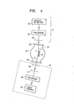
- FIG. 4 shows the fundamental arrangement of the spectrometer according to the present invention.
- An incident light supply section A is constructed of a light source 15 capable of varying visible and ultraviolet wavelengths in a wavelength range of about 200 nm to about 700 nm, a polarizer 16, and pinholes 17, 18.
- a sample section B is made up of a vacuum chamber 22 which comprises optical windows 19, 20 of quartz at both its ends, and a sample support 21 for holding a sample 1.
- a reflected light detection section C is constructed of a pinhole 23, a polarizer 24 and an optical detector 25.
- the glancing angle 8 of incident light 2 relative to the sample 1 is set so as to fulfill the condition mentioned before.
- the incident light 2 emergent from the incident light supply section A passes through the quartz window 19 and irradiates the sample 1 in the vacuum chamber 22, whereupon light 3 reflected from the sample is received by the optical detector 25 via the quartz window 20 as well as the polarizer 24.
- the incident light supply section A in Fig. 4 only that linearly polarized component of light from the light source 15 whose plane of polarization is perpendicular to the plane of incidence is derived by the polarizer 16, and it is put into a collimated beam by the pinholes 17, 18.
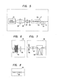
- Another embodiment of the incident light supply section A is shown in Fig. 5.
- this incident light supply section A which is constructed of a light source 15, lenses 26, 27, 28, a pinhole 29, a polarizer 30 and an optical chopper 31, light emitted from the light source 15 is focused on the pinhole 29 by the lens 26 and is put into a collimated beam by the lenses 27, 28.
- the collimated beam is led to the polarizer 30 so as to split polarization components.
- One 32 of the polarization components is used for the reference of an incident light intensity, while the other is used as incident light 2 on the sample 1.
- the incident light 2 is chopped by the optical chopper 31, and the phase sensitive detection is employed, thereby to enhance the detection sensitivity.
- Figs. 6, 7 and 8 show practicable embodiments of the light source 15. In Fig.
- the light source 15 is composed of a hollow cathode lamp 33, an electromagnet 34 and a quarter wave plate 35.
- the hollow cathode lamp 33 is inserted in the electromagnet 34, and current to flow through the electromagnet 34 is changed, whereby the wavelength of the line spectrum of an atom is changed by the effect.
- the magnetic field is applied in parallel with an optical axis as illustrated in Fig. 6, light given forth is, in general, circularly polarized light, and hence, linearly polarized light is obtained through the quarter wave plate. It is needless to say that the magnetic field can also be applied perpendicularly to the optical axis.
- the light source 15 is composed of a xenon arc lamp 36, a lens 37 and a spectrometer 38. Continuous light emitted from the xenon arc lamp 36 is focused on the slit of the spectrometer 38 by the lens 37 so as to obtain monochromatic light.
- the light source 15 is composed of a dye laser of variable wavelengths or an excimer laser of variable wavelengths 39.
- the adsorbed chemical species had a surface density of 10 13 /cm 2 or so, namely, an average distance of 30 ⁇ or so, the electronic absorption spectrum thereof could be obtained with a sufficient sensitivity.
- the electronic absorption spectrum of the visible or ultraviolet region for a chemical species adsorbed to the surface of a sample can be measured at a sufficient sensitivity without being hampered the loss in the sample.
- Such information serves as an important key for apprehending, for example, the initial process of a surface reaction, which forms the basis of semiconductor dry processing technology, and it is indispensable to developing a higher degree of processing technology.
- the present invention is also characterized in that the sample surface is not irradiated with a particle beam such as electron beam or ion beam, and that electron emission, ion emission etc. from the sample surface are not involved, either. Accordingly, when compared with a photoelectron spectrometer or a surface measurement instrument employing an electron beam or ion beam, the present invention is excellent in that the surface state is disturbed little.
- a particle beam such as electron beam or ion beam
Landscapes
- Physics & Mathematics (AREA)
- Health & Medical Sciences (AREA)
- Life Sciences & Earth Sciences (AREA)
- Chemical & Material Sciences (AREA)
- Analytical Chemistry (AREA)
- Biochemistry (AREA)
- General Health & Medical Sciences (AREA)
- General Physics & Mathematics (AREA)
- Immunology (AREA)
- Pathology (AREA)
- Investigating Or Analysing Materials By Optical Means (AREA)
Applications Claiming Priority (2)
| Application Number | Priority Date | Filing Date | Title |
|---|---|---|---|
| JP226856/83 | 1983-12-02 | ||
| JP58226856A JPS60120235A (ja) | 1983-12-02 | 1983-12-02 | 斜入射反射分光装置 |
Publications (3)
| Publication Number | Publication Date |
|---|---|
| EP0144869A2 true EP0144869A2 (de) | 1985-06-19 |
| EP0144869A3 EP0144869A3 (en) | 1986-04-09 |
| EP0144869B1 EP0144869B1 (de) | 1989-04-26 |
Family
ID=16851637
Family Applications (1)
| Application Number | Title | Priority Date | Filing Date |
|---|---|---|---|
| EP19840114155 Expired EP0144869B1 (de) | 1983-12-02 | 1984-11-23 | Reflektionsspektrometer mit streifender Inzidenz |
Country Status (5)
| Country | Link |
|---|---|
| US (1) | US4653908A (de) |
| EP (1) | EP0144869B1 (de) |
| JP (1) | JPS60120235A (de) |
| KR (1) | KR900005611B1 (de) |
| DE (1) | DE3477962D1 (de) |
Cited By (1)
| Publication number | Priority date | Publication date | Assignee | Title |
|---|---|---|---|---|
| US4810077A (en) * | 1986-02-13 | 1989-03-07 | Spectra-Tech, Inc. | Grazing angle microscope |
Families Citing this family (11)
| Publication number | Priority date | Publication date | Assignee | Title |
|---|---|---|---|---|
| JPH0632186B2 (ja) * | 1987-01-09 | 1994-04-27 | 富士写真フイルム株式会社 | フロツピ−デイスク用ケ−スの検査方法 |
| DE3737489A1 (de) * | 1987-11-02 | 1989-05-18 | Schering Ag | Verfahren zur kontrolle und/oder steuerung von metallisierungsprozessen und vorrichtung hierfuer |
| US5406082A (en) * | 1992-04-24 | 1995-04-11 | Thiokol Corporation | Surface inspection and characterization system and process |
| US5541413A (en) * | 1992-04-24 | 1996-07-30 | Thiokol Corporation | Acousto-optic tunable filter-based surface scanning system and process |
| DE19540125A1 (de) * | 1994-10-31 | 1996-05-02 | Sumitomo Chemical Co | Verfahren zur Messung des Oberflächenreflexionsgrades und Verfahren zur Herstellung einer reflexmindernden Polarisationsfolie |
| US6734967B1 (en) * | 1995-01-19 | 2004-05-11 | Kla-Tencor Technologies Corporation | Focused beam spectroscopic ellipsometry method and system |
| US5608526A (en) * | 1995-01-19 | 1997-03-04 | Tencor Instruments | Focused beam spectroscopic ellipsometry method and system |
| US5717216A (en) * | 1996-10-16 | 1998-02-10 | Reynolds Metals Company | Thickness gauging using ultraviolet light absorption |
| GB0001568D0 (en) * | 2000-01-24 | 2000-03-15 | Isis Innovation | Method and apparatus for measuring surface configuration |
| CA2628090C (en) * | 2005-11-07 | 2014-10-21 | Cardinal Cg Company | Method and apparatus for identifying photocatalytic coatings |
| CN120522464B (zh) * | 2025-07-24 | 2025-10-10 | 温州安能科技有限公司 | 一种机载非接触式验电装置及验电方法 |
Family Cites Families (11)
| Publication number | Priority date | Publication date | Assignee | Title |
|---|---|---|---|---|
| US3765773A (en) * | 1970-10-05 | 1973-10-16 | Weiner M Milton | Systems and components for the utilization of electromagnetic waves in discrete, phase-ordered media |
| US3880524A (en) * | 1973-06-25 | 1975-04-29 | Ibm | Automatic ellipsometer |
| JPS5240388A (en) * | 1975-09-26 | 1977-03-29 | Nippon Kogaku Kk <Nikon> | Spectroscopic autoellipsometer |
| FR2394789A1 (fr) * | 1976-10-26 | 1979-01-12 | Anvar | Spectroscope a reseau, a incidence rasante |
| JPS5816532B2 (ja) * | 1977-04-27 | 1983-03-31 | 赤井電機株式会社 | 積層コアの製造方法 |
| IT1115737B (it) * | 1977-10-19 | 1986-02-03 | Cise Spa | Spettografo-monocromatore ad incidenza radente |
| GB1604693A (en) * | 1978-02-16 | 1981-12-16 | Standard Telephones Cables Ltd | Optical detection of vapours |
| DE2849193A1 (de) * | 1978-11-13 | 1980-06-12 | Max Planck Gesellschaft | Einrichtung zum spektralen zerlegen elektromagnetischer strahlung |
| JPS56137233A (en) * | 1980-03-31 | 1981-10-27 | Japan Atom Energy Res Inst | Diagonal incidence spectroscope |
| JPS57132039A (en) * | 1981-02-09 | 1982-08-16 | Hitachi Ltd | Method for measuring carrier distribution |
| DE3135196A1 (de) * | 1981-09-05 | 1983-03-17 | Merck Patent Gmbh, 6100 Darmstadt | Verfahren, mittel und vorrichtung zur bestimmung biologischer komponenten |
-
1983
- 1983-12-02 JP JP58226856A patent/JPS60120235A/ja active Pending
-
1984
- 1984-11-07 KR KR1019840006966A patent/KR900005611B1/ko not_active Expired
- 1984-11-23 EP EP19840114155 patent/EP0144869B1/de not_active Expired
- 1984-11-23 DE DE8484114155T patent/DE3477962D1/de not_active Expired
- 1984-12-03 US US06/677,245 patent/US4653908A/en not_active Expired - Fee Related
Cited By (1)
| Publication number | Priority date | Publication date | Assignee | Title |
|---|---|---|---|---|
| US4810077A (en) * | 1986-02-13 | 1989-03-07 | Spectra-Tech, Inc. | Grazing angle microscope |
Also Published As
| Publication number | Publication date |
|---|---|
| US4653908A (en) | 1987-03-31 |
| KR900005611B1 (ko) | 1990-07-31 |
| EP0144869A3 (en) | 1986-04-09 |
| DE3477962D1 (en) | 1989-06-01 |
| EP0144869B1 (de) | 1989-04-26 |
| KR850005085A (ko) | 1985-08-21 |
| JPS60120235A (ja) | 1985-06-27 |
Similar Documents
| Publication | Publication Date | Title |
|---|---|---|
| KR100781745B1 (ko) | 박막 샘플을 광학적으로 특성분석하는 장치 | |
| JP3950818B2 (ja) | 反射型テラヘルツ分光測定装置及び測定方法 | |
| JPH04506998A (ja) | 光学装置 | |
| US4653908A (en) | Grazing incidence reflection spectrometer | |
| JP2008224240A (ja) | 全反射減衰型光学プローブおよびそれを用いた水溶液分光測定装置 | |
| RU2223479C2 (ru) | Способ и устройство для анализа изотопсодержащих молекул по спектру поглощения | |
| JP2002504673A (ja) | 複屈折特性測定方法および装置 | |
| Haas et al. | Analytical performance of μ-groove silicon attenuated total reflection waveguides | |
| Grassam et al. | Application of the inverse Zeeman effect to background correction in electrothermal atomic-absorption analysis | |
| GB2090971A (en) | Fluorescence polarisation analyser | |
| Kuhl et al. | A frequency doubled dye laser with a servo-tuned crystal | |
| KR100380766B1 (ko) | 액정 표시 소자를 평가하는 방법, 그 방법을 구현하는 컴퓨터 프로그램을 저장하기 위한 정보 저장 매체 및 그 저장 매체를 사용하는 평가 장치 | |
| US4310762A (en) | Calorimetric trace analysis by laser induced thermal lens method | |
| US4166697A (en) | Spectrophotometer employing magneto-optic effect | |
| EP3712578B1 (de) | Vorrichtung zur spektralanalyse und verfahren zur spektralanalyse | |
| Räty et al. | Measurement of refractive index of liquids using s-and p-polarized light | |
| US7187835B1 (en) | Mechanisms and methods for selective wavelength filtering | |
| Kebabian et al. | Determination of argon-filled insulated glass window seal failure by spectroscopic detection of oxygen | |
| Mirabella | 4 Attenuated Total Reflection | |
| Hursh et al. | Photoacoustic and spectrophotometric quantitation of copper phthalocyanine films | |
| WO2004104563A1 (ja) | 分光測定装置 | |
| US3238368A (en) | Absorption analysing apparatus with means for reflecting short wavelength ultraviolet radiation along measuring and reference optical paths | |
| JPH07208937A (ja) | 膜厚及び誘電率の測定装置及びその測定方法 | |
| RU2170913C1 (ru) | Способ выполнения спектроскопии переходного слоя проводящей поверхности | |
| Seki et al. | Oscillating beam spectrometer |
Legal Events
| Date | Code | Title | Description |
|---|---|---|---|
| PUAI | Public reference made under article 153(3) epc to a published international application that has entered the european phase |
Free format text: ORIGINAL CODE: 0009012 |
|
| 17P | Request for examination filed |
Effective date: 19841123 |
|
| AK | Designated contracting states |
Designated state(s): DE FR GB |
|
| PUAL | Search report despatched |
Free format text: ORIGINAL CODE: 0009013 |
|
| AK | Designated contracting states |
Kind code of ref document: A3 Designated state(s): DE FR GB |
|
| 17Q | First examination report despatched |
Effective date: 19871222 |
|
| GRAA | (expected) grant |
Free format text: ORIGINAL CODE: 0009210 |
|
| AK | Designated contracting states |
Kind code of ref document: B1 Designated state(s): DE FR GB |
|
| REF | Corresponds to: |
Ref document number: 3477962 Country of ref document: DE Date of ref document: 19890601 |
|
| EN | Fr: translation not filed | ||
| ET | Fr: translation filed | ||
| PLBE | No opposition filed within time limit |
Free format text: ORIGINAL CODE: 0009261 |
|
| STAA | Information on the status of an ep patent application or granted ep patent |
Free format text: STATUS: NO OPPOSITION FILED WITHIN TIME LIMIT |
|
| 26N | No opposition filed | ||
| PGFP | Annual fee paid to national office [announced via postgrant information from national office to epo] |
Ref country code: GB Payment date: 19931112 Year of fee payment: 10 |
|
| PGFP | Annual fee paid to national office [announced via postgrant information from national office to epo] |
Ref country code: FR Payment date: 19931119 Year of fee payment: 10 |
|
| PGFP | Annual fee paid to national office [announced via postgrant information from national office to epo] |
Ref country code: DE Payment date: 19931230 Year of fee payment: 10 |
|
| PG25 | Lapsed in a contracting state [announced via postgrant information from national office to epo] |
Ref country code: GB Effective date: 19941123 |
|
| GBPC | Gb: european patent ceased through non-payment of renewal fee |
Effective date: 19941123 |
|
| PG25 | Lapsed in a contracting state [announced via postgrant information from national office to epo] |
Ref country code: FR Effective date: 19950731 |
|
| PG25 | Lapsed in a contracting state [announced via postgrant information from national office to epo] |
Ref country code: DE Effective date: 19950801 |
|
| REG | Reference to a national code |
Ref country code: FR Ref legal event code: ST |