EP0144937A2 - Débitmètre à tourbillons - Google Patents
Débitmètre à tourbillons Download PDFInfo
- Publication number
- EP0144937A2 EP0144937A2 EP84114577A EP84114577A EP0144937A2 EP 0144937 A2 EP0144937 A2 EP 0144937A2 EP 84114577 A EP84114577 A EP 84114577A EP 84114577 A EP84114577 A EP 84114577A EP 0144937 A2 EP0144937 A2 EP 0144937A2
- Authority
- EP
- European Patent Office
- Prior art keywords
- vortex
- flow meter
- tube
- vortex flow
- conduit
- Prior art date
- Legal status (The legal status is an assumption and is not a legal conclusion. Google has not performed a legal analysis and makes no representation as to the accuracy of the status listed.)
- Granted
Links
Images



Classifications
-
- G—PHYSICS
- G01—MEASURING; TESTING
- G01F—MEASURING VOLUME, VOLUME FLOW, MASS FLOW OR LIQUID LEVEL; METERING BY VOLUME
- G01F1/00—Measuring the volume flow or mass flow of fluid or fluent solid material wherein the fluid passes through a meter in a continuous flow
- G01F1/05—Measuring the volume flow or mass flow of fluid or fluent solid material wherein the fluid passes through a meter in a continuous flow by using mechanical effects
- G01F1/20—Measuring the volume flow or mass flow of fluid or fluent solid material wherein the fluid passes through a meter in a continuous flow by using mechanical effects by detection of dynamic effects of the flow
- G01F1/32—Measuring the volume flow or mass flow of fluid or fluent solid material wherein the fluid passes through a meter in a continuous flow by using mechanical effects by detection of dynamic effects of the flow using swirl flowmeters
-
- G—PHYSICS
- G01—MEASURING; TESTING
- G01F—MEASURING VOLUME, VOLUME FLOW, MASS FLOW OR LIQUID LEVEL; METERING BY VOLUME
- G01F1/00—Measuring the volume flow or mass flow of fluid or fluent solid material wherein the fluid passes through a meter in a continuous flow
- G01F1/05—Measuring the volume flow or mass flow of fluid or fluent solid material wherein the fluid passes through a meter in a continuous flow by using mechanical effects
- G01F1/20—Measuring the volume flow or mass flow of fluid or fluent solid material wherein the fluid passes through a meter in a continuous flow by using mechanical effects by detection of dynamic effects of the flow
- G01F1/32—Measuring the volume flow or mass flow of fluid or fluent solid material wherein the fluid passes through a meter in a continuous flow by using mechanical effects by detection of dynamic effects of the flow using swirl flowmeters
- G01F1/325—Means for detecting quantities used as proxy variables for swirl
- G01F1/3259—Means for detecting quantities used as proxy variables for swirl for detecting fluid pressure oscillations
- G01F1/3266—Means for detecting quantities used as proxy variables for swirl for detecting fluid pressure oscillations by sensing mechanical vibrations
-
- Y—GENERAL TAGGING OF NEW TECHNOLOGICAL DEVELOPMENTS; GENERAL TAGGING OF CROSS-SECTIONAL TECHNOLOGIES SPANNING OVER SEVERAL SECTIONS OF THE IPC; TECHNICAL SUBJECTS COVERED BY FORMER USPC CROSS-REFERENCE ART COLLECTIONS [XRACs] AND DIGESTS
- Y10—TECHNICAL SUBJECTS COVERED BY FORMER USPC
- Y10S—TECHNICAL SUBJECTS COVERED BY FORMER USPC CROSS-REFERENCE ART COLLECTIONS [XRACs] AND DIGESTS
- Y10S73/00—Measuring and testing
- Y10S73/04—Piezoelectric
Definitions
- the present invention relates to a vortex flow meter for measuring a flow rate of a fluid based on Kàrmàn vortex streets, or vortex trains.
- a vortex flow meter is well known in the flow measurement art in which a vortex shedding member is positioned across a passageway inside a conduit through wich a fluid flows.
- the velocity or flow rate of the fluid in the conduit is measured by sensing pressure variations of the fluid caused by vortex trains.
- mechanical and other vibrations attributable to mechanical vibrations of the conduit, turbulent flows of the fluid itself, pulsation of a pump, and the like are apt to appear as errors in an output signal of the flow meter.
- it has boon practiced to use a sensor responsive to mechanical vibrations and a sensor responsive to vortex trains and provide a different between output signals of the two sensors.
- the problem with such an approach is that the two sensors are constructed integrally with each other but separately from the vortex shedding member and, therefore, have to be assembled independently of the latter. Especially, where the flow meter is small size, difficulty is encountered in machining and assembling it, resulting in an inefficient procedure.
- Another problem is that since the pressure variation due to a vortex train is proportional to the square of a flow rate, the flow meter needs be responsive to a wide range of pressures and, hence, its sensitivity is very low when flow rate is small. Such has hitherto been coped with by using a preamplifier having a gain which is small for large flow rates and large for small flow rates, i. e. a substantially constant total gain.
- the preamplifier with such a characteristic is susceptive to externally derived vibrations of low frequencies which contitute a source of noise. Attempts have been made to provide a stably operable vortex flow meter by compensating for the external vibrations or allowing a minimum of external vibrations to effect the measurement.
- a vortex flow meter having aconduit and a vortex sensing body which is detachably mounted in the conduit through a seal portion.
- the flow meter comprises a vortex shedding member, a vortex signal sensor, a fixing flange and an external vibration sensor which are sequentially and integrally arranged to constitute the vortex sensing body, the vortex sensing body being rigidly connected to the conduit at the fixing flange, the vortex signal sensor and the external vibration sensor being interconnected in such a manner as to cancel an externally derived vibration which acts on the vortex sensing body.
- a vortex flow meter comprising a thin-walled cylindrical tube extending throughout a center of a mounting flange and provided with a pressure receiving pate at a lower end thereof, sensing elements integrally mounted in the thin-walled cylindrical tube for converting a small pressure variation acting on the pressure receiving plate to an electrical signal, a flexible tubular member rigidly connected to the mounting flange coaxially with the thin-walled cylindrical tube in such a manner as to surround the thin-walled cylindrical tube, a hermetically sealed elastic narrow tube, a hermetically sealed terminal block, the electrical signal being outputted sequentially via the flexible tubular member, the elastic narrow tube and the terminal block, and a protective tube slidably coupled on an outer periphery of the terminal block and fixed in place while surrounding the flexible tubular member, the elastic narrow tube and the mounting flange.
- a vortex flow meter includes a vibration sensing element having a sensor responsive to an external vibration and a sensor responsive to a vortex train at vertically opposite ends thereof.
- the sensing element is fixed to a conduit fulcrumed at an intermediate portion thereof.
- a vortex shedding member is integrally and oscillatably mounted in a lower portion of the sensing element.
- the flow meter can be assembled merely by being positioned in the conduit and, due to an integral structure, it is effectively applicable even to small diameter conduits through which fluids flow at very small flow rates.
- vibration of the transducer box is prevented from reaching the sensor via the leads, thereby rendering the flow meter less susceptive to externally derived vibrations.
- vortex flow meter of the present invention is susceptible of numerous physical embodiments, depending upon the environment and requirements of use, substantial numbers of the herein shown and described embodiments have been made, tested and used, and all have performed in an eminently satisfactory manner.
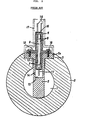
- a conduit 2 has thereinside a passageway 1 through which a desired fluid flows.
- the conduit 2 is flanged at opposite ends thereof.
- the prior art vortex flow meter comprises a body 3 which is located in an intermediate position of the conduit 2.
- a vortex shedding member, or shedder, 5 extends substantially along a diameter of the passageway 1 and is free at its lower end 5a and securely connected to the conduit 2 at its upper end 5b.
- a vibration sensor assembly, generally 6, carries sensor elements 7 responsive to a vortex signal at its lower end portion and sensor elements 8 responsive to external vibrations other than the vortex signal such as mechanical vibrations imparted to the passageway 1 at its upper end portion.
- the sensor elements 7 and 8 are commonly fixed to a flexible support member 9 by molding.
- the vortex shedder 5 is formed with a bore 10 in its upper portion.
- the lower end of the vibration sensor assembly 6 is inserted in the bore 10 to such a degree that the lower sensor elements 7 are baried in the bore 10 together with a tongue 11, which extends from the bottom of the assembly 6.
- the assembly 6 is securely yet oscillatably connected to the vortex shedder 5 at a flange 12, which is located intermediate between the ends of the assembly 6 to serve as a fulcrum.
- the portion of the element inside the bore 10 is spaced a short distance from the wall of the bore 10, while the vortex shedder 5 is provided with openings 14 at opposite ends thereof where a vortex train will be shed.
- Fig. 1 Also shown in Fig. 1 are leads 15 led out from the sensor elements 7 and 8, a molding 16 of resin, a protective tube 18 for supporting a gauge and others at its upper end while covering the sensor assembly 6, and bolts 18 for fastening the flange 12 to the vortex shedder 5.
- the sensor elements 8 responsive to mechanical vibrations and the sensor elements 7 responsive to vortex trains are built in a physically unitary structure but seprate from the vortex shedder 5.
- the sensor elements 7 and 8 have to be assembled independently of the vurtex shedder 5 at the sacrifice of efficiency.
- the inefficiency is particularly pronounced in the case of a small-size vortex flow meter with a small bore 10.
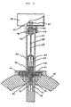
- FIG. 2 a vortex flow meter embodying the present invention is shown.
- the same or similar structural elements as those shown in Fig. 1 are designated by the same reference numerals and detailed description thereof will be omitted for simplicity.
- a vibration sensor assembly 6A carries a vortex shedder 5 rigidly at its lower end and has a flange 12 at its intermediate portion.
- the flange 12 is fastend to a cylindrical conduit 2 by means of bolts 18.
- the conduit 2 has a passageway 1 thereinside.
- the flange 12 is positioned by a stepped wall 20 which is formed at the top of a through bore 19, while a packing 21 is disposed in a peripheral portion of the stepped wall 20.
- the vortex shedder 5 is enlarged in its base portion as at 22 to reduce the spacing 23 between the vortex shedder 5 and the wall of the through bore 19.
- the vortex shedder 5 sheds a vortex flow in a fluid flowing through the passageway 1 of the conduit 2 and oscillates in proportion to a flow rate of the fluid.
- Sensor elements 7 in a lower portion of the sensor assembly 6A sense the oscillation of the vortex shedder 5.
- Vibrations undesirable for measurement such as mechanical ones caused by the flow of the fluid and those derived externally to act on the passageway 1, are sometimes imparted to the passageway 1 in the same direction as the oscillation of the vortex shedder 5. Such a kind of vibrations obviously appear as an error signal and, therefore, need be eliminated.
- This is implemented in the illustrative embodiment by upper sensor elements 8 on the sensor assembly 6A. Specifically, the sensor elements 8 constantly sense the undesirable vibrations so that their output is subtracted as an error from that of the lower sensor elements 7, L e. vortex signal. The vortex flow meter, therefore, succeeds in accurately measuring a flow rate all the time.
- the vortex flow meter can be readily assembled by fixing the sensor assembly 6A to the conduit 2 with a fulcrum defined between the upper and lower sensor elements 7 and 8 and ridily connecting the vortex shedder 5 to the bottom of the element 6A.
- the vortex flow meter may easily be designed for use with small diameter conduits in which fluids flow at very small flow rates.
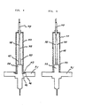
- FIG. 3 another embodiment of the present invention is shown which is provided with a unique structure for preventing externally derived vibrations from acting on electrical signals, which are output from sensor elements and passed through leads, and reaching a sensor unit to appear as noise in a pressure signal.
- a sensor is shown as being mounted in a conduit and in a section as viewed in a direction perpendicular to a direction in which a pressure variation acts on the sensor.
- the reference numeral 31 designates a flange.
- a cylindrical tube 32 having a relatively thin wall extends throughout the flange 31 and has a pressure receiving plate 35 at its bottom.
- the flange 31 is fastened to a vortex flow meter 50 by screws 44.
- a vortex train originating from the flow of a fluid in the conduit develops a delicately pressure variation which is imparted to the pressure receiving plate 35 via openings 51 to act on the thin-walled tube 32.
- the force acting on the tube 32 is transformed by sensor elements 34 such as piezoelectric elements into a quantity of electricity which is then led out of the tube 32 by leads 37.
- An insulating material 36 such as resin or glass fills the space between the tube 32 and the sensor elements 34.
- the electrical signal generated as stated above is coupled to insulated thin lines 38 and, therefrom, to an input terminal of an amplifier (not shown) inside a transducer box 70 via terminals 41 of external leads. These leads are connected to the sensor elements 34 within the flexible tube 33 and to the terminals 41 of the external leads within a terminal block 40.
- a thin-walled elastic narrow tube 39 made of stainless steel or the like is rigidly connected at one end to the tube 33 and at the other end to the terminal block 40 by welding, for example.
- the elastic narrow tube 39 comprises a sheath wire.
- the other end of the hollow tube 33 is fixed to the flange 31.
- an insulating material such as resin or glass sealingly retains the leads.
- the outer periphery of the terminal block 40 is slidably and sealingly retained by a protective tube 60 with the intermediary of an elastic sealing member 42.
- the other end of the protective tube 60 is rigidly connected to the vortex flow meter 50 while embracing the flange 31.
- the transducer box 70 is fastened to the protective tube 60 by screws 43 while covering the outer periphery of an upper portion of the latter. While the sensor elements 34 in the illustrative embodiment have been described as transforming a delicate pressure variation acting on the plate 35 into a quantity of electricity, it may additionally feature a function of compensating an external vibration other than the delicate pressure variation.
- the flexible tube 33 is provided with a radially outwardly extending lid portion 47 at its lower end for the purpose of farther reducing the bending strength of the tube 33.
- the thin-walled tube 32 extending throughout the flange 31, on the other hand, is provided with a recess along its outer peripheral edge.
- the lid portion 47 of the tube 33 is rigidly connected to a stepped portion 46 of the flange 31 by an electron beam or like fusing means while being prevented from contacting the bottom 45 of the recess of the tube 32. With such a structure the tube 33 attains a decrease in bending strength due to a longer arm of bending moment.
- a bellows 48 which forms part of the flexible tube 33.
- the bellows 48 may be positioned adjacent to the upper or lower end of the tube 33 in which case the bending strength will become even smaller than one attainable with the Fig. 4 structure.
- a hermetic seal 80 is disposed in the flexible tube 33 in order to retain the thin lines 38 so that the latter may be prevented from touching the inner wall of the tube 33 to detriment the insulation.
- the thin lines 38 extending from the sensor elements 34 are connected to the elastic narrow tube 39 by leads 81 which are insulated from each other by an insulator 82.
- Fig. 7 The modification shown in Fig. 7 is a combined version of the modifications described above with reference to Figs. 4-6.
- the second embodiment of the present invention is hardly effected by externally derived vibrations and, therefore, operable with stability in sensing vortex trains. This is because, although the moment developed by the protective tube 60 and transducer box 70 is transformed into a moment which is imparted through the elastic narrow tube 39, that moment acts on the flexible tubular member 33 and only the force transmitted through the leads 38 is allowed to act on the sensor elements 34.
- FIG. 8 Still another modification to the embodiment of Fig. 3 is shown in Fig. 8.
- the protective tube 60 is fastened at its lower and to the flow meter 50 by means of screws 91 and 92 while being spaced from the latter as at 93 and 94.
- the spaces 93 and 94 are effective to damp mechanical vibrations.
- the vortex shedder in accordance with this particular modification is provided with openings 95 for removing bubbles and openings 96 for removing impurities such as dust, in addition to the pressure variation inlet openings 51.
- the reference numeral 97 in Fig. 8 designates a packing or an O-ring.
- the 0-ring 97 is fitted in an annular recess 98 which is formed in the flow meter 50.
- the flange 31 is provided with an annular projection 31a which is engaged in the recess 98 to positively position the flange 31 relative to the flow meter 50.
Landscapes
- Physics & Mathematics (AREA)
- Fluid Mechanics (AREA)
- General Physics & Mathematics (AREA)
- Measuring Volume Flow (AREA)
Applications Claiming Priority (4)
| Application Number | Priority Date | Filing Date | Title |
|---|---|---|---|
| JP228052/83 | 1983-12-02 | ||
| JP58228052A JPS60120212A (ja) | 1983-12-02 | 1983-12-02 | 微小変動圧力検出器 |
| JP113403/84U | 1984-07-27 | ||
| JP1984113403U JPS6130823U (ja) | 1984-07-27 | 1984-07-27 | 渦流量計 |
Publications (3)
| Publication Number | Publication Date |
|---|---|
| EP0144937A2 true EP0144937A2 (fr) | 1985-06-19 |
| EP0144937A3 EP0144937A3 (en) | 1987-07-15 |
| EP0144937B1 EP0144937B1 (fr) | 1991-06-05 |
Family
ID=26452390
Family Applications (1)
| Application Number | Title | Priority Date | Filing Date |
|---|---|---|---|
| EP84114577A Expired EP0144937B1 (fr) | 1983-12-02 | 1984-11-30 | Débitmètre à tourbillons |
Country Status (5)
| Country | Link |
|---|---|
| US (1) | US4625564A (fr) |
| EP (1) | EP0144937B1 (fr) |
| KR (2) | KR890004418B1 (fr) |
| CA (1) | CA1224058A (fr) |
| DE (1) | DE3484674D1 (fr) |
Cited By (2)
| Publication number | Priority date | Publication date | Assignee | Title |
|---|---|---|---|---|
| EP0758077A1 (fr) * | 1995-08-07 | 1997-02-12 | Oval Corporation | Détecteur pour un débitmètre à induction de vortex et débitmètre à induction de vortex |
| US5869772A (en) * | 1996-11-27 | 1999-02-09 | Storer; William James A. | Vortex flowmeter including cantilevered vortex and vibration sensing beams |
Families Citing this family (15)
| Publication number | Priority date | Publication date | Assignee | Title |
|---|---|---|---|---|
| US4776222A (en) * | 1986-10-20 | 1988-10-11 | Lew Hyok S | Impulse sensor with mechanical preamplification |
| USD335096S (en) | 1987-01-28 | 1993-04-27 | David Marsh | Bluff body flowmeter |
| US4706503A (en) * | 1987-01-30 | 1987-11-17 | Itt Corporation | Vortex meter sensor |
| US5036240A (en) * | 1988-07-18 | 1991-07-30 | Lew Hyok S | Impulse sensor with mechanical preamplification and noise cancellation |
| DE4239956C2 (de) * | 1991-11-29 | 1997-05-07 | Hitachi Ltd | Elektromagnetischer Durchflußmesser |
| US5343762A (en) * | 1992-10-05 | 1994-09-06 | Rosemount Inc. | Vortex flowmeter |
| DE4441129A1 (de) * | 1994-11-21 | 1996-05-23 | Junkalor Gmbh | Meßwertgeber für einen Wirbeldurchflußmesser |
| DE19914671A1 (de) * | 1999-03-31 | 2000-11-02 | Martin Hess | Drucktransmitterinstallation an einer Prozeßleitung einer Prozeßanlage und vormontierter Installationsblock |
| US7073394B2 (en) * | 2004-04-05 | 2006-07-11 | Rosemount Inc. | Scalable averaging insertion vortex flow meter |
| US6973841B2 (en) * | 2004-04-16 | 2005-12-13 | Rosemount Inc. | High pressure retention vortex flow meter with reinforced flexure |
| JP5394506B2 (ja) | 2009-12-24 | 2014-01-22 | ローズマウント インコーポレイテッド | 渦振動センサプレートを持つ渦流量計 |
| CN103438941A (zh) * | 2013-08-14 | 2013-12-11 | 合肥精大仪表股份有限公司 | 一种通用涡街流量传感器 |
| JP2017067726A (ja) * | 2015-10-02 | 2017-04-06 | サーパス工業株式会社 | カルマン渦流量計 |
| KR20250056434A (ko) * | 2023-10-19 | 2025-04-28 | 현대자동차주식회사 | 유체의 온도측정장치 |
| CN119958653B (zh) * | 2025-01-10 | 2025-09-26 | 江苏华尔威科技集团有限公司 | 一种抗振型涡街流量计 |
Family Cites Families (4)
| Publication number | Priority date | Publication date | Assignee | Title |
|---|---|---|---|---|
| GB1601548A (en) * | 1977-05-30 | 1981-10-28 | Yokogawa Electric Works Ltd | Flow metering apparatus |
| JPS5860217A (ja) * | 1981-10-06 | 1983-04-09 | Yokogawa Hokushin Electric Corp | 渦流量計 |
| JPS5918422A (ja) * | 1982-07-22 | 1984-01-30 | Oval Eng Co Ltd | 渦流量計用振動補償装置 |
| DE3377936D1 (de) * | 1982-11-25 | 1988-10-13 | Oval Eng Co Ltd | Vortex flow meter |
-
1984
- 1984-11-30 US US06/676,752 patent/US4625564A/en not_active Expired - Lifetime
- 1984-11-30 DE DE8484114577T patent/DE3484674D1/de not_active Expired - Lifetime
- 1984-11-30 EP EP84114577A patent/EP0144937B1/fr not_active Expired
- 1984-12-01 KR KR1019890012256A patent/KR890004418B1/ko not_active Expired
- 1984-12-01 KR KR1019840007593A patent/KR890004417B1/ko not_active Expired
- 1984-12-03 CA CA000469136A patent/CA1224058A/fr not_active Expired
Cited By (4)
| Publication number | Priority date | Publication date | Assignee | Title |
|---|---|---|---|---|
| EP0758077A1 (fr) * | 1995-08-07 | 1997-02-12 | Oval Corporation | Détecteur pour un débitmètre à induction de vortex et débitmètre à induction de vortex |
| US5736647A (en) * | 1995-08-07 | 1998-04-07 | Oval Corporation | Vortex flow meter detector and vortex flow meter |
| AU700116B2 (en) * | 1995-08-07 | 1998-12-24 | Oval Corporation | Vortex flow meter detector and vortex flow meter |
| US5869772A (en) * | 1996-11-27 | 1999-02-09 | Storer; William James A. | Vortex flowmeter including cantilevered vortex and vibration sensing beams |
Also Published As
| Publication number | Publication date |
|---|---|
| KR850004632A (ko) | 1985-07-25 |
| US4625564A (en) | 1986-12-02 |
| EP0144937B1 (fr) | 1991-06-05 |
| CA1224058A (fr) | 1987-07-14 |
| KR890004418B1 (ko) | 1989-11-03 |
| EP0144937A3 (en) | 1987-07-15 |
| KR890004417B1 (ko) | 1989-11-03 |
| DE3484674D1 (de) | 1991-07-11 |
Similar Documents
| Publication | Publication Date | Title |
|---|---|---|
| US4625564A (en) | Vortex flow meter | |
| US6352000B1 (en) | Vortex flow sensor | |
| US4791818A (en) | Cantilever beam, insertable, vortex meter sensor | |
| US5447073A (en) | Multimeasurement replaceable vortex sensor | |
| US5463904A (en) | Multimeasurement vortex sensor for a vortex-generating plate | |
| JP2709618B2 (ja) | 揺動ビーム渦センサー | |
| US4788869A (en) | Apparatus for measuring fluid flow | |
| AU708934B2 (en) | Coriolis mass flowmeter | |
| US4502335A (en) | Fluid pressure transmitter assembly | |
| US5136884A (en) | Magnetic sight gage sensor | |
| US5048323A (en) | Fluid metering | |
| US3269184A (en) | Apparatus for measuring fluid characteristics | |
| JPS63158419A (ja) | コリオリの原理で作動する質量流れ測定器 | |
| CA1090606A (fr) | Capteur de pression de fluide, a membrane vibrante | |
| US4627295A (en) | Vortex flow meter | |
| US3389362A (en) | Low pressure transducer | |
| US4604891A (en) | Reference pressure devices for calibrating pressure-measuring instruments | |
| US3754446A (en) | Apparatus for measuring fluid characteristics | |
| JPS63193018A (ja) | 渦メータセンサ | |
| US4976156A (en) | Impulse sensor with balanced mass-stiffness distribution | |
| JP2004286514A (ja) | 渦流量計センサ及び渦流量計 | |
| US5321990A (en) | Vortex flow meter | |
| US2979955A (en) | Pressure responsive systems | |
| US3869920A (en) | Symmetrically arranged, deflection type differential pressure transmitters for controlling industrial systems and processes | |
| US2840675A (en) | Transducer |
Legal Events
| Date | Code | Title | Description |
|---|---|---|---|
| PUAI | Public reference made under article 153(3) epc to a published international application that has entered the european phase |
Free format text: ORIGINAL CODE: 0009012 |
|
| AK | Designated contracting states |
Designated state(s): CH DE FR GB LI NL |
|
| PUAL | Search report despatched |
Free format text: ORIGINAL CODE: 0009013 |
|
| AK | Designated contracting states |
Kind code of ref document: A3 Designated state(s): CH DE FR GB LI NL |
|
| 17P | Request for examination filed |
Effective date: 19880114 |
|
| 17Q | First examination report despatched |
Effective date: 19890524 |
|
| GRAA | (expected) grant |
Free format text: ORIGINAL CODE: 0009210 |
|
| AK | Designated contracting states |
Kind code of ref document: B1 Designated state(s): CH DE FR GB LI NL |
|
| REF | Corresponds to: |
Ref document number: 3484674 Country of ref document: DE Date of ref document: 19910711 |
|
| ET | Fr: translation filed | ||
| PLBE | No opposition filed within time limit |
Free format text: ORIGINAL CODE: 0009261 |
|
| STAA | Information on the status of an ep patent application or granted ep patent |
Free format text: STATUS: NO OPPOSITION FILED WITHIN TIME LIMIT |
|
| 26N | No opposition filed | ||
| REG | Reference to a national code |
Ref country code: GB Ref legal event code: IF02 |
|
| REG | Reference to a national code |
Ref country code: CH Ref legal event code: PFA Owner name: OVAL CORPORATION Free format text: OVAL ENGINEERING CO. LTD#10-8 KAMIOCHIAI 3-CHOME#SHINJUKU-KU/TOKYO (JP) -TRANSFER TO- OVAL CORPORATION#10-8 KAMIOCHIAI 3-CHOME SHINJUKU-KU#TOKYO (JP) |
|
| NLT1 | Nl: modifications of names registered in virtue of documents presented to the patent office pursuant to art. 16 a, paragraph 1 |
Owner name: OVAL CORPORATION |
|
| REG | Reference to a national code |
Ref country code: FR Ref legal event code: CD |
|
| PGFP | Annual fee paid to national office [announced via postgrant information from national office to epo] |
Ref country code: GB Payment date: 20031027 Year of fee payment: 20 |
|
| PGFP | Annual fee paid to national office [announced via postgrant information from national office to epo] |
Ref country code: FR Payment date: 20031120 Year of fee payment: 20 |
|
| PGFP | Annual fee paid to national office [announced via postgrant information from national office to epo] |
Ref country code: CH Payment date: 20031124 Year of fee payment: 20 |
|
| PGFP | Annual fee paid to national office [announced via postgrant information from national office to epo] |
Ref country code: NL Payment date: 20031125 Year of fee payment: 20 |
|
| PGFP | Annual fee paid to national office [announced via postgrant information from national office to epo] |
Ref country code: DE Payment date: 20031223 Year of fee payment: 20 |
|
| PG25 | Lapsed in a contracting state [announced via postgrant information from national office to epo] |
Ref country code: LI Free format text: LAPSE BECAUSE OF EXPIRATION OF PROTECTION Effective date: 20041129 Ref country code: GB Free format text: LAPSE BECAUSE OF EXPIRATION OF PROTECTION Effective date: 20041129 Ref country code: CH Free format text: LAPSE BECAUSE OF EXPIRATION OF PROTECTION Effective date: 20041129 |
|
| PG25 | Lapsed in a contracting state [announced via postgrant information from national office to epo] |
Ref country code: NL Free format text: LAPSE BECAUSE OF EXPIRATION OF PROTECTION Effective date: 20041130 |
|
| REG | Reference to a national code |
Ref country code: GB Ref legal event code: PE20 |
|
| REG | Reference to a national code |
Ref country code: CH Ref legal event code: PL |
|
| NLV7 | Nl: ceased due to reaching the maximum lifetime of a patent |
Effective date: 20041130 |