EP0144941A2 - Siebwechselvorrichtung zur Reinigung von Kunststoffschmelzen - Google Patents
Siebwechselvorrichtung zur Reinigung von Kunststoffschmelzen Download PDFInfo
- Publication number
- EP0144941A2 EP0144941A2 EP84114601A EP84114601A EP0144941A2 EP 0144941 A2 EP0144941 A2 EP 0144941A2 EP 84114601 A EP84114601 A EP 84114601A EP 84114601 A EP84114601 A EP 84114601A EP 0144941 A2 EP0144941 A2 EP 0144941A2
- Authority
- EP
- European Patent Office
- Prior art keywords
- housing
- bore
- flow
- opening
- openings
- Prior art date
- Legal status (The legal status is an assumption and is not a legal conclusion. Google has not performed a legal analysis and makes no representation as to the accuracy of the status listed.)
- Granted
Links
Images

Classifications
-
- B—PERFORMING OPERATIONS; TRANSPORTING
- B29—WORKING OF PLASTICS; WORKING OF SUBSTANCES IN A PLASTIC STATE IN GENERAL
- B29C—SHAPING OR JOINING OF PLASTICS; SHAPING OF MATERIAL IN A PLASTIC STATE, NOT OTHERWISE PROVIDED FOR; AFTER-TREATMENT OF THE SHAPED PRODUCTS, e.g. REPAIRING
- B29C48/00—Extrusion moulding, i.e. expressing the moulding material through a die or nozzle which imparts the desired form; Apparatus therefor
- B29C48/25—Component parts, details or accessories; Auxiliary operations
- B29C48/36—Means for plasticising or homogenising the moulding material or forcing it through the nozzle or die
- B29C48/50—Details of extruders
- B29C48/69—Filters or screens for the moulding material
- B29C48/691—Arrangements for replacing filters, e.g. with two parallel filters for alternate use
- B29C48/6914—Arrangements for replacing filters, e.g. with two parallel filters for alternate use the filters being fitted on a rotatable or pivotable disc or on the circumference of a rotatable or pivotable cylinder
-
- B—PERFORMING OPERATIONS; TRANSPORTING
- B29—WORKING OF PLASTICS; WORKING OF SUBSTANCES IN A PLASTIC STATE IN GENERAL
- B29B—PREPARATION OR PRETREATMENT OF THE MATERIAL TO BE SHAPED; MAKING GRANULES OR PREFORMS; RECOVERY OF PLASTICS OR OTHER CONSTITUENTS OF WASTE MATERIAL CONTAINING PLASTICS
- B29B7/00—Mixing; Kneading
- B29B7/30—Mixing; Kneading continuous, with mechanical mixing or kneading devices
- B29B7/58—Component parts, details or accessories; Auxiliary operations
-
- B—PERFORMING OPERATIONS; TRANSPORTING
- B29—WORKING OF PLASTICS; WORKING OF SUBSTANCES IN A PLASTIC STATE IN GENERAL
- B29C—SHAPING OR JOINING OF PLASTICS; SHAPING OF MATERIAL IN A PLASTIC STATE, NOT OTHERWISE PROVIDED FOR; AFTER-TREATMENT OF THE SHAPED PRODUCTS, e.g. REPAIRING
- B29C48/00—Extrusion moulding, i.e. expressing the moulding material through a die or nozzle which imparts the desired form; Apparatus therefor
- B29C48/03—Extrusion moulding, i.e. expressing the moulding material through a die or nozzle which imparts the desired form; Apparatus therefor characterised by the shape of the extruded material at extrusion
Definitions
- the invention relates to a screening device according to the preamble of claim 1.
- the openings of the plates or disks which are displaceable or rotatable within the housing are alternately introduced into the flow channel of the high-pressure press.
- screening devices are known from DE-AS 21 53 962.
- the pressure conditions of the plastic melt change, since the air present in the breakthrough entering the flow channel must be displaced by the plastic melt. Under unfavorable circumstances, this also leads to the formation of bubbles in the plastic melt, since the air located in the breakthrough in question is partially enclosed by the plastic melt.
- the invention has for its object to improve a screening device of the generic type in such a way that the continuity of the plastic melt is largely preserved when a breakthrough occurs in the flow channel.
- the breakthrough By venting the breakthrough that is to be introduced next into the throughflow hole, the breakthrough enters the region of the flow channel practically without interruption, since the plastic melt is no longer impaired in terms of printing technology and no more air pockets can get into the plastic melt. Because of the venting, the above-mentioned breakthrough can be filled with melt when entering the flow channel without any appreciable increase in pressure. H. be flooded.
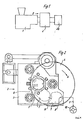
- plastic is plasticized in a manner known per se and then passed through a screening device 2 and cleaned there. Starting from the screening device 2, the cleaned plastic melt is fed to a tool 30.
- the screening device consists essentially of a housing 3 and a rotatably mounted disc 4. Inside the housing 3, a flow hole 5 is arranged, which forms part of the flow channel of the high-pressure press 1. A sieve disk 6 is arranged in this through-bore 5.
- the disc 4 is equipped with several openings 7.
- the disk 4 is provided on its entire circumference with the openings 7 mentioned, so that part of the openings
- the breakthroughs 7 can be brought into the area of the flow-through bore 5 by rotating the disk 4 in a constant change.
- the sieve device can also be formed from an elongated, slide-like plate which has a corresponding number of openings.
- the openings are alternately brought into the area of the throughflow hole by translationally pushing the plate back and forth.
- the openings 7 within the disc 4 take impurities lying in front of the sieve disc 6 as they pass through the housing 3 and thus contribute to cleaning the sieve disc 6 at.
- FIG. 2 shows an operating phase in which an opening 7 lies in the area of the through-bore 5.
- the direction of rotation of the disc 4 is indicated by the arrow A.
- FIG. 3 the same construction is basically provided.
- a disk 4 rotates according to arrow A within the housing 3.
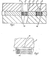
- the openings 7 themselves are provided with screen disks 6a, as illustrated in FIG. 3.
- the flow hole 5, however, is left here without a sieve.
- the individual sieve disks 6a lying in the openings 7 are brought alternately into the flow-through bore 5 by the rotation of the disk 4.
- a suction bore 8 is provided in the housing 3 and is connected to a suction pump 10 via a line 9.
- the breakthrough 7 to be introduced next into the throughflow bore 5 is evacuated via the overflow channel 11 and the adjacent breakthrough 7, which in turn is acted upon directly by the suction bore 8.
- the length of the overflow channel 7 corresponds at least to the width of a web 12 which separates two openings 7 located one behind the other.
Landscapes
- Engineering & Computer Science (AREA)
- Mechanical Engineering (AREA)
- Processing And Handling Of Plastics And Other Materials For Molding In General (AREA)
- Extrusion Moulding Of Plastics Or The Like (AREA)
- Cleaning By Liquid Or Steam (AREA)
Abstract
Description
- Die Erfindung betrifft eine Siebvorrichtung gemäß Gattungsbegriff des Patentanspruches 1.
- Bei Siebvorrichtungen der gattungsgemäßen Art werden bestimmungsgemäß die Durchbrüche der innerhalb des Gehäuses verschiebbaren oder drehbaren Platten oder Scheiben wechselweise in den Fließkanal der Hochdruckpresse eingebracht. Derartige Siebvorrichtungen sind aus der DE-AS 21 53 962 bekannt. Immer wenn ein neuer Durchbruch in den Bereich des Fließkanales eintritt, ändern sich die Druckverhältnisse der Kunststoffschmelze, da die in dem neu in den Fließkanal eintretenden Durchbruch vorhandene Luft von der Kunststoffschmelze verdrängt werden muß. Dies führt unter ungünstigen Umständen auch zu einer Blasenbildung in der Kunststoffschmelze, da die in dem betroffenen Durchbruch befindliche Luft teilweise von der Kunststoffschmelze umschlossen wird.
- Der Erfindung liegt die Aufgabe zugrunde, eine Siebvorrichtung der gattungsgemäßen Art dahingehend zu verbessern, daß die Kontinuität der Kunststoffschmelze beim Eintreten eines Durchbruches in den Fließkanal weitestgehend erhalten bleibt.
- Die erfindungsgemäße Lösung ergibt sich aus dem kennzeichnenden Teil des Patentanspruches 1.
- Durch die Entlüftung des als nächster in die Durchflußbohrung einzubringenden Durchbruches erfolgt der Eintritt des Durchbruches in den Bereich des Fließkanales praktisch störungsfrei, da die Kunststoffschmelze drucktechnisch nicht mehr beeinträchtigt wird und auch keine Lufteinschlüsse mehr in die Kunststoffschmelze gelangen können. Durch die Entlüftung nämlich kann der genannte Durchbruch beim Eintreten in den Fließkanal ohne nennenswerten Druckanstieg mit Schmelze ausgefüllt, d. h. geflutet werden.
- Die Erfindung weiterbildende Merkmale sind Gegenstand von Unteransprüchen. Hervorzuheben ist dabei die Ausgestaltung, daß mit einer Absaugpumpe unmittelbar über eine Absaugbohrung auf einen weiteren, an den als nächsten in die Durchflußbohrung einzubringenden Durchbruch angrenzenden Durchbruch einzuwirken, wobei diese beiden Durchbrüche strömungstechnisch miteinander verbunden sind. Hierdurch ist bei zuverlässiger Evakuierung des als nächster in die Durchflußbohrung einzubringenden Durchbruches zugleich die Mündung der Absaugbohrung so weit von der Durchflußbohrung ferngehalten, daß beim Evakuieren nicht etwa unbeabsichtigt Kunststoffschmelze mit angesaugt werden kann.
- Ausführungsbeispiele der Erfindung werden nachstehend unter Bezugnahme auf die beigefügte Zeichnung näher beschrieben.
- Es zeigen
- Figur eine schematische Darstellung einer Hochdruckpresse mit Siebvorrichtung und nachgeschaltetem Werkzeug,
- Figur 2 eine Ansicht der Siebvorrichtung in Richtung des Pfeiles II in Figur 1,
- Figur 3 eine der Figur 2 entsprechende Ansicht einer Siebvorrichtung nach einem weiteren Ausfuhrungsbeispiel der Erfindung,
- Figur 4 einen Schnitt nach IV-IV in Figur 3,
- Figur 5 einen Teilschnitt nach der Linie V-V in Figur 3.
- In der in Figur 1 dargestellten Hochdruckpresse 1 wird Kunststoff in an sich bekannter Weise plastifiziert und anschließend durch eine Siebvorrichtung 2 geführt und dort gereinigt. Von der Siebvorrichtung 2 ausgehend wird die gereinigte Kunststoffschmelze einem Werkzeug 30 zugeführt.
- Bei dem in den Figuren 2 und 3 dargestellten Ausführungsbeispiel besteht die Siebvorrichtung im wesentlichen aus einem Gehäuse 3 und einer darin drehbar gelagerten Scheibe 4. Innerhalb des Gehäuses 3 ist eine Durchflußbohrung 5 angeordnet, die einen Teil des Fließkanales der Hochdruckpresse 1 bildet. In dieser Durchflußbohrung 5 ist eine Siebscheibe 6 angeordnet.
- Die Scheibe 4 ist mit mehreren Durchbrüchen 7 ausgestattet. Die Scheibe 4 ist an ihrem ganzen Umfang mit den erwähnten Durchbrüchen 7 versehen, so daß sich ein Teil der Durchbrüche
- immer innerhalb des Gehäuses 3 befindet, während andere Durchbrüche sich außerhalb des Gehäuses befinden. Die Durchbrüche 7 können durch Drehung der Scheibe 4 in stetigem Wechsel in den Bereich der Durchflußbohrung 5 gebracht werden.
- Abweichend von dieser Ausgestaltung kann die Siebvorrichtung auch aus einer länglichen, schiebeartigen Platte gebildet sein, die eine entsprechende Anzahl von Durchbrüchen trägt. In diesem Fall werden durch translatorisches Hin- und Herschieben der Platte die Durchbrüche im Wechsel in den Bereich der Durchflußbohrung gebracht.
- Bei dem Ausführungsbeispiel nach Figur 2, bei dem die Siebscheibe 6 innerhalb der Durchflußbohrung 5 angeordnet ist, nehmen die Durchbrüche 7 innerhalb der Scheibe 4 bei ihrem Durchlauf durch das Gehäuse 3 vor der Siebscheibe 6 liegende Verunreinigungen mit und tragen so zu einer Säuberung der Siebscheibe 6 bei.
- In Figur 2 ist eine Betriebsphase dargestellt, in der ein Durchbruch 7 im Bereich der Durchflußbohrung 5 liegt. Die Drehrichtung der Scheibe 4 ist durch den Pfeil A gekennzeichnet. Durch Drehung der Scheibe gelangt der an den vorgenannten Durchbruch angrenzende, in Figur2 noch außerhalb der Durchflußbohrung 4 liegende Durchbruch dann als nächster in die Durchflußbohrung 5. Die Kunststoffschmelze muß nun den Bereich des neu eintretenden Durchbruches 7 ausfüllen. Um dieses zu gewährleisten, ist im dargestellten Ausführungsbeispiel innerhalb des Gehäuses 3 und im Durchlaufbereich der Durchbrüche 7 eine Absaugbohrung 8 angebracht, die über eine Leitung 9 mit einer Absaugbohrung 10 verbunden ist. über diese Absaugpumpe 10 wird jeder Durchbruch 7, bevor er in die Durchflußbohrung 5 eingebracht wird, evakuiert. Die Anordnung ist nun so getroffen, daß die Absaugbohrung 8 so weit entfernt von der Durchflußbohrung 5 mündet, daß zwischen dem unmittelbar beaufschlagten Durchbruch und der Durchflußbohrung 5 noch ein weiterer Durchbruch 7 liegt, der naturgemäß schon früher unmittelbar evakuiert wurde. Dieser als nächster in die Durchflußbohrung 5 einzubringende Durchbruch 7 bleibt jedoch mit dem unmittelbar beaufschlagten Durchbruch 7 strömungstechnisch leitend verbunden, so daß seine Evakuierung aufrechterhalten bleibt. Hierzu ist innerhalb des Gehäuses 3 ein überströmkanal 11 vorgesehen, der die beiden genannten Durchbrüche 7 miteinander verbindet. Die Evakuierung erfolgt somit in jedem Fall auch dann noch, wenn der betreffende Durchbruch 7 als nächster in die Durchflußbohrung 5 eintritt, so daß die dann in ihn einströmende Kunststoffschmelze schnell und problemlos die Ausfüllung des Durchbruches erzielen kann, während andererseits ein unbeabsichtigtes Ansaugen von Kunststoffschmelze mittels der Absaugpumpe 10 vermieden ist.
- Bei dem in den Figuren 3-5 dargestellten Ausführungsbeispiel ist grundsätzlich die gleiche Konstruktion vorgesehen. Es dreht eine Scheibe 4 gemäß Pfeil A innerhalb des Gehäuses 3. Bei dieser Ausführungsform sind jedoch die Durchbrüche 7 selbst mit Siebscheiben 6a versehen, wie in Figur 3 illustriert. Die Durchflußbohrung 5 ist dagegen hier ohne Siebscheibe belassen. Die einzelnen in den Durchbrüchen 7 liegenden Siebscheiben 6a werden durch die Drehung der Scheibe 4 wechselweise in die Durchflußbohrung 5 gebracht. Auch bei dieser Ausführungsform ist in der gleichen Weise wie beim Ausführungsbeispiel nach Figur 2 im Gehäuse 3 eine Absaugbohrung 8 vorgesehen, die über eine Leitung 9 mit einer Absaugpumpe 10 verbunden ist. Auch hier wird der als nächster in die Durchflußbohrung 5 einzubringende Durchbruch 7 über den überströmkanal 11 und den angrenzenden Durchbruch 7, der seinerseits unmittelbar von der Absaugbohrung 8 beaufschlagt wird, evakuiert.
- Die Länge des Überströmkanales 7 entspricht mindestens der Breite eines Steges 12, der zwei hintereinanderliegende Durchbrüche 7 voneinander trennt.
- Es gibt Kunststoffschmelzen, deren Verhalten gegenüber der Luft im Durchbruch es ermöglichen, auf eine Evakuierung zu verzichten. In so einem Fall kommt man ohne die Absaugpumpe aus. Es genügt, wenn die Luft z. B. über das oben geschilderte Kanalsystem nach außen entweichen kann.
-
- 1 Hochdruckpresse
- 2 Siebvorrichtung
- 3 Gehäuse.
- 4 Scheibe
- 5 Durchflußbohrung
- 6 Siebscheibe
- 6a Siebscheibe.
- 7 Durchbruch
- 8 Absaugbohrung
- 9 Leitung
- 10 Absaugpumpe
- 11 Überströmkanal
- 12 Steg
- 30 Werkzeug
Claims (4)
Priority Applications (1)
| Application Number | Priority Date | Filing Date | Title |
|---|---|---|---|
| AT84114601T ATE46652T1 (de) | 1983-12-06 | 1984-12-01 | Siebwechselvorrichtung zur reinigung von kunststoffschmelzen. |
Applications Claiming Priority (2)
| Application Number | Priority Date | Filing Date | Title |
|---|---|---|---|
| DE3344002 | 1983-12-06 | ||
| DE3344002 | 1983-12-06 |
Publications (3)
| Publication Number | Publication Date |
|---|---|
| EP0144941A2 true EP0144941A2 (de) | 1985-06-19 |
| EP0144941A3 EP0144941A3 (en) | 1986-05-07 |
| EP0144941B1 EP0144941B1 (de) | 1989-09-27 |
Family
ID=6216131
Family Applications (1)
| Application Number | Title | Priority Date | Filing Date |
|---|---|---|---|
| EP84114601A Expired EP0144941B1 (de) | 1983-12-06 | 1984-12-01 | Siebwechselvorrichtung zur Reinigung von Kunststoffschmelzen |
Country Status (3)
| Country | Link |
|---|---|
| US (1) | US4588502A (de) |
| EP (1) | EP0144941B1 (de) |
| AT (1) | ATE46652T1 (de) |
Cited By (3)
| Publication number | Priority date | Publication date | Assignee | Title |
|---|---|---|---|---|
| EP0287048A3 (de) * | 1987-04-17 | 1990-04-18 | Pat Plastic Equipment Ltd. | Anlage zum Filtrieren |
| EP0510592A3 (en) * | 1991-04-25 | 1993-01-13 | Gneuss Kunststofftechnik Gmbh | Filters for plastic melts |
| US6582598B2 (en) | 2000-12-14 | 2003-06-24 | Hubert Patrovsky | Wave filter for rotary filter |
Families Citing this family (14)
| Publication number | Priority date | Publication date | Assignee | Title |
|---|---|---|---|---|
| DE3606138C1 (de) * | 1986-02-26 | 1987-05-07 | Kreyenborg Verwaltungen | Filtereinrichtung fuer Strangpressen und Spritzgiessmaschinen fuer schaeumbare Thermoplasten |
| DE8716626U1 (de) * | 1987-12-17 | 1988-02-11 | Gneuß Kunststofftechnik GmbH, 4970 Bad Oeynhausen | Siebvorrichtung zur Reinigung von Kunststoffschmelzen |
| US6250532B1 (en) * | 1991-10-18 | 2001-06-26 | United States Surgical Corporation | Surgical stapling apparatus |
| EP0569866B1 (de) | 1992-05-11 | 1996-03-13 | GNEUSS KUNSTSTOFFTECHNIK GmbH | Filter für Kunststoffschmelzen |
| DE4240461C1 (de) * | 1992-12-02 | 1993-12-09 | Gneuss Kunststofftechnik Gmbh | Schmelzefilter für die Reinigung von Kunststoffschmelzen |
| US5417866A (en) * | 1993-07-02 | 1995-05-23 | Extek, Inc. | Continuous flow polymer filtration apparatus and process |
| US5516426A (en) * | 1995-02-21 | 1996-05-14 | Hull; Harold L. | Self-cleaning filter system |
| US6010625A (en) * | 1997-10-16 | 2000-01-04 | Beringer Llc | Screen changer with controlled gap |
| US20080179261A1 (en) * | 2007-01-31 | 2008-07-31 | Hubert Patrovsky | Single disc dual flow rotary filter |
| US8262908B2 (en) * | 2007-08-22 | 2012-09-11 | Hubert Patrovsky | Rotary cartridge filter |
| EP3308940B1 (de) * | 2016-10-17 | 2025-03-05 | Next Generation Analytics GmbH | Filtersystem für viskose oder hochviskose flüssigkeiten, insbesondere kunststoffschmelzen und verfahren zur filtration von viskosen oder hochviskosen flüssigkeiten |
| US11260570B2 (en) * | 2018-05-07 | 2022-03-01 | PSI-Polymer Systems, Inc. | Filtration apparatuses and screen changer devices for polymer processing and related methods |
| DE102021115905B4 (de) * | 2021-06-18 | 2023-04-27 | Gneuss Gmbh | Mehrwegeventileinheit für Kunststoffschmelzen und andere mittel- bis hochviskose Flüssigkeiten |
| DE102022102820B4 (de) * | 2022-02-07 | 2023-12-21 | Gneuss Gmbh | Filtriervorrichtung für PVC-Kunststoffschmelze zur Verbindung mit einem Doppelschneckenextruder und Doppelschneckenextruder für die PVC-Verarbeitung |
Family Cites Families (8)
| Publication number | Priority date | Publication date | Assignee | Title |
|---|---|---|---|---|
| US2765085A (en) * | 1954-02-24 | 1956-10-02 | Black Clawson Co | Rotary suction drum filter |
| US3146494A (en) * | 1961-11-13 | 1964-09-01 | Nat Rubber Machinery Co | Extruder with reverse flow flushed breaker plate assembly |
| US3269611A (en) * | 1964-02-04 | 1966-08-30 | Komarek Greaves And Company | Feeding mechanism |
| FR1554913A (de) * | 1967-12-15 | 1969-01-24 | ||
| US4025434A (en) * | 1975-10-06 | 1977-05-24 | Bolton-Emerson, Inc. | Screen changer with pre-fill screen blocks |
| US3983038A (en) * | 1975-11-03 | 1976-09-28 | Heston Eugene E | Self-purging screen changer and strainer plate |
| JPS5927698B2 (ja) * | 1977-11-28 | 1984-07-07 | 株式会社日本製鋼所 | プラスチツク押出機における自動「ろ」網交換装置 |
| DE3302343C2 (de) * | 1983-01-25 | 1985-10-24 | Rehau Plastiks Ag + Co, 8673 Rehau | Siebwechselvorrichtung |
-
1984
- 1984-09-06 US US06/647,929 patent/US4588502A/en not_active Expired - Fee Related
- 1984-12-01 AT AT84114601T patent/ATE46652T1/de not_active IP Right Cessation
- 1984-12-01 EP EP84114601A patent/EP0144941B1/de not_active Expired
Cited By (3)
| Publication number | Priority date | Publication date | Assignee | Title |
|---|---|---|---|---|
| EP0287048A3 (de) * | 1987-04-17 | 1990-04-18 | Pat Plastic Equipment Ltd. | Anlage zum Filtrieren |
| EP0510592A3 (en) * | 1991-04-25 | 1993-01-13 | Gneuss Kunststofftechnik Gmbh | Filters for plastic melts |
| US6582598B2 (en) | 2000-12-14 | 2003-06-24 | Hubert Patrovsky | Wave filter for rotary filter |
Also Published As
| Publication number | Publication date |
|---|---|
| EP0144941A3 (en) | 1986-05-07 |
| EP0144941B1 (de) | 1989-09-27 |
| ATE46652T1 (de) | 1989-10-15 |
| US4588502A (en) | 1986-05-13 |
Similar Documents
| Publication | Publication Date | Title |
|---|---|---|
| EP0144941A2 (de) | Siebwechselvorrichtung zur Reinigung von Kunststoffschmelzen | |
| DE4119216C2 (de) | Tropfenabscheider | |
| DE3905963C2 (de) | Polymer-Filtervorrichtung | |
| EP0523313B1 (de) | Siebelement | |
| DE1294820B (de) | Stroemungsdrossel, bestehend aus mindestens einem Paar von koaxialen, nacheinander durchstroemten zylindrischen Wirbelkammern | |
| DE2339057A1 (de) | Filtervorrichtung mit kontinuierlichem schrittweisen vorschub | |
| DE3013038A1 (de) | Siebwechselvorrichtung fuer extruder | |
| EP0569866A1 (de) | Filter für Kunststoffschmelzen | |
| DE3518997C1 (de) | Schneckenstrangpresse mit einer Zylindertemperiereinrichtung | |
| DE2748224A1 (de) | Plattenwaermetauscher | |
| DE2554645A1 (de) | Automatische filtersieb-wechselvorrichtung fuer einen extruder | |
| DE2740523A1 (de) | Plattenfoermiger kondensator | |
| DE1817774B2 (de) | Pneumatischer Anwesenheitsfühler | |
| DE2652405B2 (de) | Verfahren zum Filtrieren von Feststoffe enthaltendem Wasser sowie Filter zur Durchführung des Verfahrens | |
| DE2610691C3 (de) | Vorrichtung zum Führen der Stoffsuspension in einem Stoffauflauf einer Papiermaschine | |
| DE1504596A1 (de) | Platten-Extrusionswerkzeug | |
| DE3443654A1 (de) | Siebvorrichtung zur reinigung von kunststoffschmelzen | |
| DE3230597C1 (de) | Roststab fuer Rostbelaege,insbesondere von Feuerungen | |
| DE2942849C2 (de) | Filtereinrichtung für Strangpressen | |
| DE3328243A1 (de) | Sortiermaschine | |
| DE3126849C2 (de) | ||
| EP1755763A1 (de) | Tropfenabscheideranordnung | |
| DE6606527U (de) | Vorrichtung zum stranggiessen eines bandes | |
| DE4037774C1 (de) | ||
| EP1245366A2 (de) | Sperrmittel zur Steuerung des Durchflusses eines fliessfähigen Mediums |
Legal Events
| Date | Code | Title | Description |
|---|---|---|---|
| PUAI | Public reference made under article 153(3) epc to a published international application that has entered the european phase |
Free format text: ORIGINAL CODE: 0009012 |
|
| AK | Designated contracting states |
Designated state(s): AT CH FR GB IT LI NL |
|
| PUAL | Search report despatched |
Free format text: ORIGINAL CODE: 0009013 |
|
| AK | Designated contracting states |
Kind code of ref document: A3 Designated state(s): AT CH FR GB IT LI NL |
|
| 17P | Request for examination filed |
Effective date: 19860521 |
|
| 17Q | First examination report despatched |
Effective date: 19871201 |
|
| ITF | It: translation for a ep patent filed | ||
| GRAA | (expected) grant |
Free format text: ORIGINAL CODE: 0009210 |
|
| AK | Designated contracting states |
Kind code of ref document: B1 Designated state(s): AT GB IT |
|
| REF | Corresponds to: |
Ref document number: 46652 Country of ref document: AT Date of ref document: 19891015 Kind code of ref document: T |
|
| GBT | Gb: translation of ep patent filed (gb section 77(6)(a)/1977) | ||
| EN | Fr: translation not filed | ||
| PLBE | No opposition filed within time limit |
Free format text: ORIGINAL CODE: 0009261 |
|
| STAA | Information on the status of an ep patent application or granted ep patent |
Free format text: STATUS: NO OPPOSITION FILED WITHIN TIME LIMIT |
|
| 26N | No opposition filed | ||
| PGFP | Annual fee paid to national office [announced via postgrant information from national office to epo] |
Ref country code: GB Payment date: 19911129 Year of fee payment: 8 |
|
| PGFP | Annual fee paid to national office [announced via postgrant information from national office to epo] |
Ref country code: AT Payment date: 19911230 Year of fee payment: 8 |
|
| ITTA | It: last paid annual fee | ||
| PG25 | Lapsed in a contracting state [announced via postgrant information from national office to epo] |
Ref country code: GB Effective date: 19921201 Ref country code: AT Effective date: 19921201 |
|
| GBPC | Gb: european patent ceased through non-payment of renewal fee |
Effective date: 19921201 |