EP0144974B1 - Plattenkassette - Google Patents
Plattenkassette Download PDFInfo
- Publication number
- EP0144974B1 EP0144974B1 EP84114819A EP84114819A EP0144974B1 EP 0144974 B1 EP0144974 B1 EP 0144974B1 EP 84114819 A EP84114819 A EP 84114819A EP 84114819 A EP84114819 A EP 84114819A EP 0144974 B1 EP0144974 B1 EP 0144974B1
- Authority
- EP
- European Patent Office
- Prior art keywords
- disc
- resilient deformable
- disc cartridge
- shutter member
- deformable means
- Prior art date
- Legal status (The legal status is an assumption and is not a legal conclusion. Google has not performed a legal analysis and makes no representation as to the accuracy of the status listed.)
- Expired
Links
Images


Classifications
-
- G—PHYSICS
- G11—INFORMATION STORAGE
- G11B—INFORMATION STORAGE BASED ON RELATIVE MOVEMENT BETWEEN RECORD CARRIER AND TRANSDUCER
- G11B23/00—Record carriers not specific to the method of recording or reproducing; Accessories, e.g. containers, specially adapted for co-operation with the recording or reproducing apparatus ; Intermediate mediums; Apparatus or processes specially adapted for their manufacture
- G11B23/02—Containers; Storing means both adapted to cooperate with the recording or reproducing means
- G11B23/03—Containers for flat record carriers
- G11B23/033—Containers for flat record carriers for flexible discs
- G11B23/0332—Containers for flat record carriers for flexible discs for single discs, e.g. envelopes
Definitions
- the present invention relates to a disc cartridge having shutter means for shutting head insertion openings of the disc cartridge.
- FIGs. 1 to 4 there is shown a conventional disc cartridge as disclosed in GB-A-2 100 048, wherein a top half 1a and a bottom half 1 b are assembled together to form a disc cartridge 1 and a magnetic floppy disc 2 is rotatably enclosed in a chamber formed between the top half la and the bottom half 1b.
- a shutter 3 having a pair of opposed plates 3a and 3b connected by a front plate 3c as shown in Fig. 3 is movably fitted to the recessed portion 4 of the disc cartridge 1 for opening and closing a head insertion hole 7.
- the resistance of the deformation of the recessed portion is high since the wall of the recessed portion 4 is in the form of a beam supported at the both side edges by the side walls of the disc cartridge, having a flat plate member, therefore, the recessed portion 4 is not easily deformed by the projection 5 in the process of mounting of the shutter 3, whereby the force for inserting the shutter 3 changes from one disc cartridge to another, and there tends to occur incorrect mounting of the shutter to the disc cartridge such as breakdown.
- EP-A-137 965 which is regarded to belonging to the prior art according to Art. 54(3) EPC shows a disc cartridge having tapered edges on the top and bottom halves for guiding the projections of the shutter member when the shutter member is assembled to the disc case. Behind the tapered edges, the projections of the shutter member engage corresponding guide slots.
- the provision of the slit according to claim 2 makes the resilient deformable portion to be easily deformed when the projection of the shutter rides over the resilient deformable means, so that the shutter can easily be assembled to the disc cartridge with a reduced force, whereby the work of assembling of the shutter can be improved and break down of the disc cartridge can be effectively prevented.
- the top half 1 a and the bottom half 1 b of the disc case 1 are formed by molding plastic resin materials and the magnetic or optical recording disc 2 is rotatably enclosed in the disc cartridge with a hub 14 of the recording disc 2 faced to drive shaft insertion holes 13 defined on the top and bottom halves 1a a and 1 b.
- Head insertion holes 7 are defined on the top and bottom halves 1a a and 1b extending in the radial direction of the recording disc 2 and when the top half 1a and the bottom half 1b are assembled together the head insertion holes 7 are opposed each other.
- Each of the head insertion holes 7 serves as a pad insertion hole.
- the shutter 3 is movably mounted on the recessed portion for closing and opening the head insertion holes 7.
- the shutter 3 When the disc cartridge is mounted in a disc drive device, the shutter 3 is moved to open the head insertion holes 7 and a recording head and a pad in the disc drive device are contacted to the recording disc 2 for recording or reproducing.
- the shutter 3 is made of a stainless steel plate formed in a generally U character shape in side view and is provided with a pair of holes 8a and 8b similar to the head insertion hole 7 in a similar manner as shown in Figs. 1 and 3.
- a pair of holes 8a and 8b similar to the head insertion hole 7 in a similar manner as shown in Figs. 1 and 3.
- a slit 12 on the front edge portion of the bottom half 1 b so as to extend from the front end of the bottom half 1 b to the guide slot 6 so that an elongated resilient deformable portion 10 is formed in a cantilever manner surrounded by the guide slot 6 and the slit 12.
- the resilient deformable portion 10 is supported by a connecting member 11 which is protruded from the front end portion of the bottom half 1b, thus there are two resilient deformable portions 10 and 10a formed on the both sides of the connecting member 11.
- the resilient deformable portions 10 and 10a are respectively spaced from an edge of the slot 6 by gaps 101 and 101a (Fig. 5).
- the length of the space between the ends of the portions 10 and 10a is defined corresponding to the length of the space X between the two projections 5 of the shutter 3 (see Fig. 1).
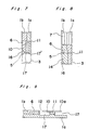
- the projections 5 push the resilient deformable portions 10 and 10a downward deforming the portions 10 and 10a into the space 17 between the front portion of the top and bottom halves 1a a and 1b, and in turn the projections 5 can be entered in the guide slot 6 riding over the resilient deformable portions 10 and 10a, then the resilient deformable portions 10 can recover to the original straight shape, thus the shutter 3 can be moved in both lateral directions guided along the guide slot 6, preventing disengagement of the projection 5 from the guide slot 6.
- the upper front end portion of the resilient deformable portion 10 may be beveled as shown at the reference numeral 16 in Fig. 7 so as for the projection 5 to be facilitated to ride over the resilient deformable portion 10 and insertion of the projection 6 in the guide slot 6.
- the length I of the portions 10 and 10a can be as long as possible, so that the deformation resistance can be decreased.
- the front edge portion of the top half 1a a is formed with a right angle corner 17' for preventing erroneous assembling of the shutter member with the top and bottom reversed.
- the portion 10 may be single. By providing the portion 10 only one, it makes possible to enlarge the resilient deformable portion 10 so that the resistance of the deformation of the resilient deformable portion 10 may be small.
Landscapes
- Packaging Of Annular Or Rod-Shaped Articles, Wearing Apparel, Cassettes, Or The Like (AREA)
- Packaging For Recording Disks (AREA)
Claims (5)
Applications Claiming Priority (2)
| Application Number | Priority Date | Filing Date | Title |
|---|---|---|---|
| JP58232558A JPH0772987B2 (ja) | 1983-12-08 | 1983-12-08 | デイスクカートリツジ |
| JP232558/83 | 1983-12-08 |
Publications (3)
| Publication Number | Publication Date |
|---|---|
| EP0144974A2 EP0144974A2 (de) | 1985-06-19 |
| EP0144974A3 EP0144974A3 (en) | 1985-11-06 |
| EP0144974B1 true EP0144974B1 (de) | 1989-10-11 |
Family
ID=16941205
Family Applications (1)
| Application Number | Title | Priority Date | Filing Date |
|---|---|---|---|
| EP84114819A Expired EP0144974B1 (de) | 1983-12-08 | 1984-12-05 | Plattenkassette |
Country Status (4)
| Country | Link |
|---|---|
| US (1) | US4579225A (de) |
| EP (1) | EP0144974B1 (de) |
| JP (1) | JPH0772987B2 (de) |
| DE (1) | DE3480132D1 (de) |
Families Citing this family (12)
| Publication number | Priority date | Publication date | Assignee | Title |
|---|---|---|---|---|
| US4698714A (en) * | 1984-04-28 | 1987-10-06 | Sony Corporation | Flexible magnetic disc cassette |
| JPH0627029Y2 (ja) * | 1984-06-01 | 1994-07-20 | 富士写真フイルム株式会社 | 磁気ディスクカートリッジ |
| KR950000953B1 (ko) * | 1985-05-09 | 1995-02-06 | 히다찌마구세루 가부시기가이샤 | 디스크 카트리지 |
| KR950000954B1 (ko) * | 1985-05-20 | 1995-02-06 | 히다찌마구세루 가부시기가이샤 | 디스크 카트리지 |
| JPH0740423B2 (ja) * | 1986-03-01 | 1995-05-01 | 日立マクセル株式会社 | デイスクカ−トリツジ |
| GB2208330B (en) * | 1987-07-27 | 1991-12-04 | Hitachi Ltd | An optical disc cartridge and a mechanism for preventing an incorrect insertion of a cartridge. |
| JPS63266678A (ja) * | 1987-12-24 | 1988-11-02 | Sony Corp | フロッピーディスクカセット |
| GB8806419D0 (en) * | 1988-03-18 | 1988-04-20 | Du Pont | Improvements relating to fibres |
| JP2607054B2 (ja) * | 1994-12-27 | 1997-05-07 | 株式会社日立製作所 | ディスクカートリッジ |
| WO1998007150A1 (en) * | 1996-08-08 | 1998-02-19 | Fuji Photo Film Co., Ltd. | Magnetic disk cartridge |
| US6459544B1 (en) | 1998-11-20 | 2002-10-01 | Bruce M. Harper | Removable cartridge for data-storage medium |
| WO2002093576A1 (en) * | 2001-05-11 | 2002-11-21 | Sony Corporation | Information recording medium cartridge |
Family Cites Families (6)
| Publication number | Priority date | Publication date | Assignee | Title |
|---|---|---|---|---|
| AU558371B2 (en) * | 1981-05-30 | 1987-01-29 | Sony Corporation | Flexible magnetic disc cassette |
| JPS5897166A (ja) * | 1981-12-03 | 1983-06-09 | Sony Corp | フロツピ−デイスクカセツト |
| JPS6038535Y2 (ja) * | 1981-12-15 | 1985-11-18 | ソニー株式会社 | カセツトケ−ス |
| JPS58155674U (ja) * | 1982-04-09 | 1983-10-18 | ソニー株式会社 | 磁気デイスク装置 |
| JPS59153672U (ja) * | 1983-03-29 | 1984-10-15 | ソニー株式会社 | 記録再生用デイスクカセツト |
| EP0137965B1 (de) * | 1983-08-20 | 1989-04-05 | Hitachi Maxell Ltd. | Plattenkassette |
-
1983
- 1983-12-08 JP JP58232558A patent/JPH0772987B2/ja not_active Expired - Fee Related
-
1984
- 1984-12-05 EP EP84114819A patent/EP0144974B1/de not_active Expired
- 1984-12-05 DE DE8484114819T patent/DE3480132D1/de not_active Expired
- 1984-12-06 US US06/678,817 patent/US4579225A/en not_active Expired - Fee Related
Also Published As
| Publication number | Publication date |
|---|---|
| DE3480132D1 (en) | 1989-11-16 |
| US4579225A (en) | 1986-04-01 |
| EP0144974A3 (en) | 1985-11-06 |
| JPS60124079A (ja) | 1985-07-02 |
| JPH0772987B2 (ja) | 1995-08-02 |
| EP0144974A2 (de) | 1985-06-19 |
Similar Documents
| Publication | Publication Date | Title |
|---|---|---|
| EP0201870A2 (de) | Verschluss für Plattenkassette | |
| EP0202660B1 (de) | Plattenbehälter | |
| US4579225A (en) | Disc cartridge | |
| EP0336637B1 (de) | Plattenkassette | |
| US5606547A (en) | Optical disc cartridge and mechanism for preventing an incorrect insertion of a cartridge | |
| EP0691650B1 (de) | Plattenkassette | |
| EP0077566B1 (de) | Plattenkassette (Plattehülle) | |
| US5554052A (en) | Locking connector | |
| EP0094087B1 (de) | Aufnahmebandkassette | |
| EP0785554A2 (de) | Plattenkassette und Verfahren zu deren Herstellung und Giessform dafür | |
| EP0218231A2 (de) | Verschluss für Plattenkassette | |
| CA1176749A (en) | Tape cassette storage box | |
| EP0139146B1 (de) | Hülle für eine Aufzeichnungsplatte | |
| CA2022676A1 (en) | Magnetic disk cartridge | |
| EP0060497A1 (de) | Magnetbandkassette | |
| CA1120151A (en) | Magnetic recording tape cartridge | |
| US5524005A (en) | Cartridge for a recording reproducing medium having a shutter configured to reduce damage to the casing | |
| US5561573A (en) | Method of assembling a tape cassette and securing a plate spring and shield plate therein | |
| AU683625B2 (en) | Disk cartridge | |
| EP0320492B1 (de) | Aufnahme-Plattenkassette | |
| KR850002852Y1 (ko) | 개폐가능한 슬라이드 파스너용 개리 감삽구 | |
| JP3485761B2 (ja) | ディスクカートリッジ | |
| JPH0333985Y2 (de) | ||
| HK1008448B (en) | Disc cartridge | |
| HK1008448A1 (en) | Disc cartridge |
Legal Events
| Date | Code | Title | Description |
|---|---|---|---|
| PUAI | Public reference made under article 153(3) epc to a published international application that has entered the european phase |
Free format text: ORIGINAL CODE: 0009012 |
|
| AK | Designated contracting states |
Designated state(s): DE GB |
|
| PUAL | Search report despatched |
Free format text: ORIGINAL CODE: 0009013 |
|
| AK | Designated contracting states |
Designated state(s): DE GB |
|
| 17P | Request for examination filed |
Effective date: 19860307 |
|
| 17Q | First examination report despatched |
Effective date: 19880104 |
|
| GRAA | (expected) grant |
Free format text: ORIGINAL CODE: 0009210 |
|
| AK | Designated contracting states |
Kind code of ref document: B1 Designated state(s): DE GB |
|
| REF | Corresponds to: |
Ref document number: 3480132 Country of ref document: DE Date of ref document: 19891116 |
|
| PLBE | No opposition filed within time limit |
Free format text: ORIGINAL CODE: 0009261 |
|
| STAA | Information on the status of an ep patent application or granted ep patent |
Free format text: STATUS: NO OPPOSITION FILED WITHIN TIME LIMIT |
|
| 26N | No opposition filed | ||
| PGFP | Annual fee paid to national office [announced via postgrant information from national office to epo] |
Ref country code: GB Payment date: 19931125 Year of fee payment: 10 |
|
| PGFP | Annual fee paid to national office [announced via postgrant information from national office to epo] |
Ref country code: DE Payment date: 19931228 Year of fee payment: 10 |
|
| PG25 | Lapsed in a contracting state [announced via postgrant information from national office to epo] |
Ref country code: GB Effective date: 19941205 |
|
| GBPC | Gb: european patent ceased through non-payment of renewal fee |
Effective date: 19941205 |
|
| PG25 | Lapsed in a contracting state [announced via postgrant information from national office to epo] |
Ref country code: DE Effective date: 19950901 |