EP0145020A2 - Compensateur pour conduites ou similaires, qui véhiculent des gaz d'échappement chauds - Google Patents
Compensateur pour conduites ou similaires, qui véhiculent des gaz d'échappement chauds Download PDFInfo
- Publication number
- EP0145020A2 EP0145020A2 EP84115295A EP84115295A EP0145020A2 EP 0145020 A2 EP0145020 A2 EP 0145020A2 EP 84115295 A EP84115295 A EP 84115295A EP 84115295 A EP84115295 A EP 84115295A EP 0145020 A2 EP0145020 A2 EP 0145020A2
- Authority
- EP
- European Patent Office
- Prior art keywords
- metal
- compensator
- fabric
- compensator according
- hoses
- Prior art date
- Legal status (The legal status is an assumption and is not a legal conclusion. Google has not performed a legal analysis and makes no representation as to the accuracy of the status listed.)
- Granted
Links
Images
Classifications
-
- F—MECHANICAL ENGINEERING; LIGHTING; HEATING; WEAPONS; BLASTING
- F16—ENGINEERING ELEMENTS AND UNITS; GENERAL MEASURES FOR PRODUCING AND MAINTAINING EFFECTIVE FUNCTIONING OF MACHINES OR INSTALLATIONS; THERMAL INSULATION IN GENERAL
- F16L—PIPES; JOINTS OR FITTINGS FOR PIPES; SUPPORTS FOR PIPES, CABLES OR PROTECTIVE TUBING; MEANS FOR THERMAL INSULATION IN GENERAL
- F16L27/00—Adjustable joints; Joints allowing movement
- F16L27/10—Adjustable joints; Joints allowing movement comprising a flexible connection only
- F16L27/107—Adjustable joints; Joints allowing movement comprising a flexible connection only the ends of the pipe being interconnected by a flexible sleeve
Definitions
- the invention relates to a compensator for hot exhaust gas leading lines or connecting pieces, consisting of an at least flexible tubular body made of heat-resistant material, which is intended for bridging two mutually opposite line ends or connecting pieces and compensates vibrations of the lines or connecting pieces by damping.
- the object of the invention is therefore to provide an at least flexible compensator of the type mentioned, which is fire-proof and gas-tight and has improved vibration and sound damping properties.
- the solution of this object is characterized in that the gas-tight formed tubular body has an inner tube made of silicate g ewebe which is surrounded coaxially by at least one further hose of heat-resistant fabric, that with respect to the gas flow in the tubular body by at least one of the tubes shielded metal support stabilizes the cross section of the hose structure and that the hoses are sewn together at least at their end regions with a metal wire.
- a compensator according to the invention fulfills the properties that it can withstand very high temperatures, for example up to approximately 1500 ° C., and is gas-tight even at higher exhaust gas pressures. Furthermore, the compensator has very good vibration and sound damping properties, which can be attributed to the use and the layer structure of its tissue-like hoses.
- the fabric sleeves of the compensator are made of plastic material, when the exhaust gases flow through the compensator, there are no environmentally harmful pollutants, since the silicate fabric of the compensator is asbestos-free.
- the compensator is light in weight and at least flexible, so that an axial offset, for example, to be connected to cable ends does not constitute an obstacle to assembly.
- the compensator according to the invention has a low thermal conductivity, so that it acts as a temperature spreading brake.
- a special embodiment of the invention consists in that a single or multi-layer metal foil is provided as a gas diffusion barrier at least between two adjacent tubes. This configuration allows the formation of a particularly highly effective gas diffusion barrier.
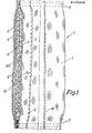
- FIG. 1 shows the first embodiment of a compensator 1 in the form of a tubular body which, for example, generally has a length of approximately 10 to 30 cm, but can also be made longer.
- the compensator consists of an inner tube 2 made of silicate ewebe g and at least one further tube 3 of heat-resistant fabric that surrounds the inner tube 2 koaxiäl.
- a further hose 4 made of heat-resistant material is provided, which surrounds the hose 3 on the outside, the hoses 3 and 4 preferably also consisting of silicate fabric, which is not absolutely necessary, however.
- a metal support 5 is provided, which in this case consists of a flexible metal wire mesh which is shaped into a tubular body.
- an envelope-shaped gas diffusion barrier 6 is provided, which in the case shown consists of a two-layer metal foil, the one envelope-shaped metal foil 6a between the inner tube 2 and the metal support 5 and the other envelope-shaped shaped metal foil 6b is provided between the metal support and the further tube 3.
- the metal foils can consist of aluminum foil, for example, and are used as separate inserts in the case shown. However, it can also be done in such a way that the hoses 2, 3 and 4 are already provided on the corresponding sides with a coating serving as a gas diffusion barrier. This is shown, for example, in the case of the outer tube 4, in which the gas-tight or diffusion-tight coating 6c is identified by a thicker and continuous line. It should also be noted that the outer tube 4 can also be used without a diffusion barrier.
- the procedure can also be such that the silicate fabric of the hoses 2, 3 and 4 is woven so tightly that a separate gas diffusion barrier is not necessary.
- the dense weave of the silicate fabric in connection with the fact that several hoses are used to form the compensator can be sufficient as a diffusion barrier in some applications, especially when the exhaust gas pressures of the hot exhaust gases flowing through the compensator are only a lower value than that Have atmospheric pressure. It may be sufficient here that only one of the hoses is woven gas-tight.
- the ends of the tubes, including the gas diffusion barrier 6, which may be provided separately, are sewn together, which is shown by the schematically shown seams 7 and 8.
- these seams can consist of a single seam or a multiple seam, as shown schematically.
- a metal wire is used as the suture material, which is advantageously coated with a textile material for better handling and for optical reasons of the compensator.
- the correspondingly cut sheets of silicate fabric are longitudinally sewn, as is indicated by the dashed seams 9 and 10.
- the provision of longitudinal seams ensures that the gas diffusion barrier is only pierced by a minimum value.
- the sewn hoses 2, 3 and 4 are advantageously turned so that the seams 9, 10, etc. come to rest on the inside of the hose in question.
- the hoses are then coaxially mounted together with the tubular, supporting metal wire mesh 5 and with the optionally provided metal foils 6a, 6b and sewn together at the ends according to the seams 7 and 8.
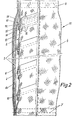
- the further embodiment according to FIG. 2 shows a compensator 11, which is preferably designed as a longer hose.
- This compensator differs essentially from the compensator 1 in that it has a metal coil 12 as a metal support, which preferably consists of a metal wire.
- this metal coil is sewn into a coiled fabric sheet 13, so that this fabric sheet forms the inner tube of the compensator, which is exposed to the gas flow.
- the edge regions 15 of the coiled fabric web overlap with such a width that the wire helix 12 is sewn into the overlap region.
- double seams 14 are preferably provided on both sides of the metal helix 12, which are shown in dash-dot lines.
- these seams 14 are only shown at the top in FIG.
- a metal thread is used, which is covered with a textile material. It is irrelevant that the textile material of the metal thread burns when the compensator is used later, since it only has to be ensured that a durable seam is provided.
- the edge areas 15 In order to prevent the edge of the edge regions 15 from being used frayed fabric web 13 during operation of the compensator, the edge areas have a double-layered hem 16, the seams being guided so that they run into the hem or in the seams 16.
- the inner tube formed in this way from the fabric web 13 is then coaxially surrounded by the diffusion barrier 6 already mentioned, the barrier then in turn being surrounded by the additional tube 3, preferably silicate fabric.
- the further hose 4 can then be provided with a further integrated gas diffusion barrier 6c.
- the ends of the compensator 11 are sewn to the seams 7 and 8 in the manner already mentioned. While the coiled fabric web 13 forming the inner tube is inevitably also sewn helically, the two outer tubes 3 and 4 made of silicate fabric are provided with the longitudinal seams 9 and 10 already mentioned.
- the compensator 1 according to FIG. 1 is essentially only flexible, the other compensator 11 according to FIG. 2 additionally has considerable flexibility in the axial direction, which can be attributed to the metal helix 12.
- the compensator 11 according to FIG. 2 is used essentially when the compensator must have larger dimensions than the compensator 1 according to FIG. 1.
- the compensator 11 can have a diameter of about 100 mm and a length, for example up to several meters, although overall larger dimensions are possible.
- a further advantage, in particular of the compensator 11, is that it heats up slightly on the outside during use, in general only becoming lukewarm, so that it can be stored after use without paying particular attention to the risk of fire.
- Silicate fabric is to be understood as a known fabric, the fibers of which generally consist of at least about 90% Si 02 .
- Such a fabric must be provided for the inner hose, since it is directly exposed to the high temperatures of hot exhaust gases.
- a mixed fabric can also be used for the following hoses or their fabrics, which, in addition to silicate fibers, also has other high-melting fibers with low thermal conductivity, which, for example, consist of glass fibers and can be used, for example, for the fabric of the outermost tube.
- a further metal wire mesh 5 and / or also a metal helix 12 can be used for the compensator 1, as is also possible to additionally use a wire mesh 5 for the compensator 11.
Landscapes
- Engineering & Computer Science (AREA)
- General Engineering & Computer Science (AREA)
- Mechanical Engineering (AREA)
- Rigid Pipes And Flexible Pipes (AREA)
- Woven Fabrics (AREA)
- Pipe Accessories (AREA)
- Supports For Pipes And Cables (AREA)
- Chairs Characterized By Structure (AREA)
- Joints Allowing Movement (AREA)
Priority Applications (1)
| Application Number | Priority Date | Filing Date | Title |
|---|---|---|---|
| AT84115295T ATE41218T1 (de) | 1983-12-14 | 1984-12-12 | Kompensator fuer leitungen oder dergleichen, die heisse abgase fuehren. |
Applications Claiming Priority (2)
| Application Number | Priority Date | Filing Date | Title |
|---|---|---|---|
| DE19833345179 DE3345179A1 (de) | 1983-12-14 | 1983-12-14 | Kompensator fuer leitungen oder dergleichen, die heisse abgase fuehren |
| DE3345179 | 1983-12-14 |
Publications (3)
| Publication Number | Publication Date |
|---|---|
| EP0145020A2 true EP0145020A2 (fr) | 1985-06-19 |
| EP0145020A3 EP0145020A3 (en) | 1986-12-30 |
| EP0145020B1 EP0145020B1 (fr) | 1989-03-08 |
Family
ID=6216885
Family Applications (1)
| Application Number | Title | Priority Date | Filing Date |
|---|---|---|---|
| EP84115295A Expired EP0145020B1 (fr) | 1983-12-14 | 1984-12-12 | Compensateur pour conduites ou similaires, qui véhiculent des gaz d'échappement chauds |
Country Status (3)
| Country | Link |
|---|---|
| EP (1) | EP0145020B1 (fr) |
| AT (1) | ATE41218T1 (fr) |
| DE (2) | DE3345179A1 (fr) |
Cited By (6)
| Publication number | Priority date | Publication date | Assignee | Title |
|---|---|---|---|---|
| GB2272737A (en) * | 1991-05-17 | 1994-05-25 | Tokai Rubber Ind Ltd | Flexible joint for exhaust pipe of motor vehicle |
| FR2758588A1 (fr) * | 1997-01-23 | 1998-07-24 | Hutchinson | Flexible de decouplage monte dans une ligne d'echappement d'un moteur de vehicule automobile |
| WO2001081814A1 (fr) * | 2000-04-22 | 2001-11-01 | Straub-Werke Ag | Raccord pour tuyaux |
| DE102009034186A1 (de) | 2009-07-22 | 2011-02-03 | Man Diesel & Turbo Se | Ausrichten eines Zylinderkopfes eines Verbrennungsmotors |
| DE102009037219A1 (de) | 2009-08-12 | 2011-02-17 | Man Diesel & Turbo Se | Montieren eines Zylinderkopfes auf einem Zylindergehäuse |
| US12072058B2 (en) | 2019-08-08 | 2024-08-27 | Norma Germany Gmbh | Clamp assembly with a heat protection device |
Family Cites Families (4)
| Publication number | Priority date | Publication date | Assignee | Title |
|---|---|---|---|---|
| US3197850A (en) * | 1959-07-09 | 1965-08-03 | Martin M Gracer | Feeder for producing stock material |
| US3874711A (en) * | 1974-02-06 | 1975-04-01 | Westinghouse Electric Corp | Gas turbine exhaust system expansion joint |
| FR2266095A1 (en) * | 1974-03-29 | 1975-10-24 | Sema | Composite concentric flexible sleeve joint for hot ducts - using abrasion resistant and insulating matls. in an expansion joint |
| DE2445055C3 (de) * | 1974-09-20 | 1978-10-12 | Guenther 6078 Zeppelinheim Merz | Gasdichter Weichstoffkompensator |
-
1983
- 1983-12-14 DE DE19833345179 patent/DE3345179A1/de not_active Withdrawn
-
1984
- 1984-12-12 EP EP84115295A patent/EP0145020B1/fr not_active Expired
- 1984-12-12 DE DE8484115295T patent/DE3477046D1/de not_active Expired
- 1984-12-12 AT AT84115295T patent/ATE41218T1/de not_active IP Right Cessation
Cited By (10)
| Publication number | Priority date | Publication date | Assignee | Title |
|---|---|---|---|---|
| GB2272737A (en) * | 1991-05-17 | 1994-05-25 | Tokai Rubber Ind Ltd | Flexible joint for exhaust pipe of motor vehicle |
| US5390962A (en) * | 1991-05-17 | 1995-02-21 | Tokai Rubber Industries, Ltd. | Flexible joint for exhaust pipe of motor vehicle |
| GB2272737B (en) * | 1991-05-17 | 1995-08-23 | Tokai Rubber Ind Ltd | Flexible joint for exhaust pipe of motor vehicle |
| FR2758588A1 (fr) * | 1997-01-23 | 1998-07-24 | Hutchinson | Flexible de decouplage monte dans une ligne d'echappement d'un moteur de vehicule automobile |
| EP0855496A1 (fr) * | 1997-01-23 | 1998-07-29 | Hutchinson | Flexible de découplage monté dans une ligne d'échappement d'un moteur de véchicule automobile |
| WO1998032957A1 (fr) * | 1997-01-23 | 1998-07-30 | Hutchinson | Flexible de decouplage monte dans une ligne d'echappement d'un moteur de vehicule automobile |
| WO2001081814A1 (fr) * | 2000-04-22 | 2001-11-01 | Straub-Werke Ag | Raccord pour tuyaux |
| DE102009034186A1 (de) | 2009-07-22 | 2011-02-03 | Man Diesel & Turbo Se | Ausrichten eines Zylinderkopfes eines Verbrennungsmotors |
| DE102009037219A1 (de) | 2009-08-12 | 2011-02-17 | Man Diesel & Turbo Se | Montieren eines Zylinderkopfes auf einem Zylindergehäuse |
| US12072058B2 (en) | 2019-08-08 | 2024-08-27 | Norma Germany Gmbh | Clamp assembly with a heat protection device |
Also Published As
| Publication number | Publication date |
|---|---|
| DE3345179A1 (de) | 1985-06-27 |
| DE3477046D1 (en) | 1989-04-13 |
| EP0145020B1 (fr) | 1989-03-08 |
| EP0145020A3 (en) | 1986-12-30 |
| ATE41218T1 (de) | 1989-03-15 |
Similar Documents
| Publication | Publication Date | Title |
|---|---|---|
| EP0615595B1 (fr) | Dispositif de raccordement flexible pour deux elements tubulaires, notamment pour systemes de gaz d'echappement de vehicules | |
| EP0856648B1 (fr) | Elément de conduite flexible pour conduites de gaz d'échappement | |
| EP0797039B1 (fr) | Elément de tuyau avec soufflet métallique | |
| EP0282689B1 (fr) | Elément de conduite flexible pour conduites de gas d'échappement de moteurs à combustion interne | |
| DE9002752U1 (de) | Flexibles Leitungselement mit Wärmeisolierung | |
| DE19641963C1 (de) | Leitungselement mit einem Balg aus Metall | |
| DE3702243A1 (de) | Flexible abgasleitung fuer kraftfahrzeuge | |
| DE3440459C2 (fr) | ||
| DE4415860A1 (de) | Flexibles Leitungselement für Abgasleitungen von Verbrennungsmotoren bei Kraftfahrzeugen | |
| EP0145020B1 (fr) | Compensateur pour conduites ou similaires, qui véhiculent des gaz d'échappement chauds | |
| DE9015414U1 (de) | Schalldämmendes Luft- oder Gasführungselement | |
| EP0193072B1 (fr) | Dispositif d'épuration catalytique des gaz d'échappement | |
| DE102013106075B4 (de) | Vorrichtung zum schwingungsentkoppelten Verbinden zweier Einrichtungen einer Abgasanlage | |
| DE112015001782T5 (de) | Hitzeschild | |
| DE102009052834A1 (de) | Thermoisoliertes Doppelmetallrohr | |
| DE3506626A1 (de) | Flexibles abgasrohr fuer ein kraftfahrzeug | |
| DE202007004757U1 (de) | Entkoppelelement mit Isolation | |
| EP0281685B1 (fr) | Soufflet servant comme compensateur | |
| DE3411935C2 (de) | Wärmedämmende Verkleidung für eine Wand, insbesondere von Gasleitungen | |
| EP3631268A1 (fr) | Élément coupe-feu et bandage coupe-feu | |
| DE2908367B2 (de) | Anordnung zur lösbaren, dichten, gelenkigen und elastisch nachgiebigen Verbindung zweier heißgehender, ein- oder mehrflutiger Rohrleitungen | |
| DE4214883A1 (de) | Kompensationselement für Kunststoffmantelrohrleitungen | |
| DE19848451A1 (de) | Flexibles Leitungselement | |
| WO2005024197A1 (fr) | Element de conduite flexible | |
| DE10103383C1 (de) | Doppelwandige Anschlussleitung |
Legal Events
| Date | Code | Title | Description |
|---|---|---|---|
| PUAI | Public reference made under article 153(3) epc to a published international application that has entered the european phase |
Free format text: ORIGINAL CODE: 0009012 |
|
| AK | Designated contracting states |
Designated state(s): AT BE CH DE FR GB IT LI LU NL SE |
|
| PUAL | Search report despatched |
Free format text: ORIGINAL CODE: 0009013 |
|
| AK | Designated contracting states |
Kind code of ref document: A3 Designated state(s): AT BE CH DE FR GB IT LI LU NL SE |
|
| 17P | Request for examination filed |
Effective date: 19870220 |
|
| 17Q | First examination report despatched |
Effective date: 19880603 |
|
| GRAA | (expected) grant |
Free format text: ORIGINAL CODE: 0009210 |
|
| AK | Designated contracting states |
Kind code of ref document: B1 Designated state(s): AT BE CH DE FR GB IT LI LU NL SE |
|
| PG25 | Lapsed in a contracting state [announced via postgrant information from national office to epo] |
Ref country code: SE Effective date: 19890308 Ref country code: NL Effective date: 19890308 Ref country code: IT Free format text: LAPSE BECAUSE OF FAILURE TO SUBMIT A TRANSLATION OF THE DESCRIPTION OR TO PAY THE FEE WITHIN THE PRESCRIBED TIME-LIMIT;WARNING: LAPSES OF ITALIAN PATENTS WITH EFFECTIVE DATE BEFORE 2007 MAY HAVE OCCURRED AT ANY TIME BEFORE 2007. THE CORRECT EFFECTIVE DATE MAY BE DIFFERENT FROM THE ONE RECORDED. Effective date: 19890308 Ref country code: FR Free format text: THE PATENT HAS BEEN ANNULLED BY A DECISION OF A NATIONAL AUTHORITY Effective date: 19890308 Ref country code: BE Effective date: 19890308 |
|
| REF | Corresponds to: |
Ref document number: 41218 Country of ref document: AT Date of ref document: 19890315 Kind code of ref document: T |
|
| REF | Corresponds to: |
Ref document number: 3477046 Country of ref document: DE Date of ref document: 19890413 |
|
| GBT | Gb: translation of ep patent filed (gb section 77(6)(a)/1977) | ||
| EN | Fr: translation not filed | ||
| NLV1 | Nl: lapsed or annulled due to failure to fulfill the requirements of art. 29p and 29m of the patents act | ||
| PG25 | Lapsed in a contracting state [announced via postgrant information from national office to epo] |
Ref country code: AT Effective date: 19891212 |
|
| PG25 | Lapsed in a contracting state [announced via postgrant information from national office to epo] |
Ref country code: LU Free format text: LAPSE BECAUSE OF NON-PAYMENT OF DUE FEES Effective date: 19891231 |
|
| PLBE | No opposition filed within time limit |
Free format text: ORIGINAL CODE: 0009261 |
|
| STAA | Information on the status of an ep patent application or granted ep patent |
Free format text: STATUS: NO OPPOSITION FILED WITHIN TIME LIMIT |
|
| 26N | No opposition filed | ||
| PGFP | Annual fee paid to national office [announced via postgrant information from national office to epo] |
Ref country code: GB Payment date: 20001215 Year of fee payment: 17 |
|
| PGFP | Annual fee paid to national office [announced via postgrant information from national office to epo] |
Ref country code: CH Payment date: 20001229 Year of fee payment: 17 |
|
| PGFP | Annual fee paid to national office [announced via postgrant information from national office to epo] |
Ref country code: DE Payment date: 20010228 Year of fee payment: 17 |
|
| PG25 | Lapsed in a contracting state [announced via postgrant information from national office to epo] |
Ref country code: GB Free format text: LAPSE BECAUSE OF NON-PAYMENT OF DUE FEES Effective date: 20011212 |
|
| PG25 | Lapsed in a contracting state [announced via postgrant information from national office to epo] |
Ref country code: LI Free format text: LAPSE BECAUSE OF NON-PAYMENT OF DUE FEES Effective date: 20011231 Ref country code: CH Free format text: LAPSE BECAUSE OF NON-PAYMENT OF DUE FEES Effective date: 20011231 |
|
| REG | Reference to a national code |
Ref country code: GB Ref legal event code: IF02 |
|
| PG25 | Lapsed in a contracting state [announced via postgrant information from national office to epo] |
Ref country code: DE Free format text: LAPSE BECAUSE OF NON-PAYMENT OF DUE FEES Effective date: 20020702 |
|
| GBPC | Gb: european patent ceased through non-payment of renewal fee |
Effective date: 20011212 |
|
| REG | Reference to a national code |
Ref country code: CH Ref legal event code: PL |