EP0145046A2 - Verfahren zum Generieren von Objekten in einem Videobild - Google Patents
Verfahren zum Generieren von Objekten in einem Videobild Download PDFInfo
- Publication number
- EP0145046A2 EP0145046A2 EP84201491A EP84201491A EP0145046A2 EP 0145046 A2 EP0145046 A2 EP 0145046A2 EP 84201491 A EP84201491 A EP 84201491A EP 84201491 A EP84201491 A EP 84201491A EP 0145046 A2 EP0145046 A2 EP 0145046A2
- Authority
- EP
- European Patent Office
- Prior art keywords
- segment
- memory
- image
- address
- topological
- Prior art date
- Legal status (The legal status is an assumption and is not a legal conclusion. Google has not performed a legal analysis and makes no representation as to the accuracy of the status listed.)
- Granted
Links
Images

Classifications
-
- G—PHYSICS
- G09—EDUCATION; CRYPTOGRAPHY; DISPLAY; ADVERTISING; SEALS
- G09G—ARRANGEMENTS OR CIRCUITS FOR CONTROL OF INDICATING DEVICES USING STATIC MEANS TO PRESENT VARIABLE INFORMATION
- G09G5/00—Control arrangements or circuits for visual indicators common to cathode-ray tube indicators and other visual indicators
- G09G5/42—Control arrangements or circuits for visual indicators common to cathode-ray tube indicators and other visual indicators characterised by the display of patterns using a display memory without fixed position correspondence between the display memory contents and the display position on the screen
Definitions
- the present invention relates to a method for generating in an image described by a succession of lines in connection with line and frame synchronization signals, objects represented by a series of segments one above the other, each corresponding to a line of the image.
- It relates, in general, to the display of video images and more particularly to the generation of a plurality of mobile objects on a video screen, within the framework of video game systems, in which a microprocessor is used to manage the 'a whole system and change the position of objects by modifying the content of memories.
- known video generators compare the X and Y coordinates of the first significant point of the mobile to the content of counters which follow the position of the spot of a cathode-ray tube.
- Such a method is described, for example, in United States patent US Pat . No. 4,116,444 in which an extractor and comparator element checks, for each line of image, whether the latter includes an object, by reading each time the entire contents of a memory containing the coordinates of the objects.
- the method according to the present invention avoids these drawbacks and makes it possible to easily treat a large number of objects together. It also makes it possible to process a background landscape using the same procedure as moving objects, which simplifies programming of the complete image and offers additional possibilities for animation.
- said address register consists of two stacks, one containing for each object number the address, fixed at least for the duration of a frame, of the start of the description of said object in the shape memory. , and the other containing a starting address corresponding to the description of a segment of the object, starting address which is modified each time that a new segment different from the previous one must be represented.
- the groups of data indicating the start of a segment at the exact place where this segment begins are recorded at predetermined positions according to a regular grid in the topological memory, and these data groups include, in addition to the object number, a series of bits indicating the value of the offset between the exact position of the segment and the position of the data group.
- An improvement which saves space in memory consists in additionally recording in each group of data of the topological memory a bit known as "repetition" indicating if necessary that, when the same number is found later. object, it is the same segment which must then be represented again, and in that, after having read the starting address in the address register, this same address is left there in the case of a repetition, whereas it is replaced by that of the next segment otherwise.
- each segment in the shape memory is subdivided into sub-segments whose representation in the image has a constant determined length, except for the last sub -segment of a segment, in that at the top of each chain of data describing a sub-segment, the address of the corresponding sub-segment of the next segment is placed, and in what is provided in the topological memory for positions corresponding to non-representable imaginary image line portions located at left and outside the image.
- topological memories each corresponding to a plane image and which together exploit a common shape memory, and then to establish priorities between the topological memories, that is to say between the numbers of objects to be represented resulting from the simultaneous reading of the different topological memories.
- form the set of points or "pixels” constituting the image of an object when it is analyzed according to the television frame.
- Such a form is made up of a series of "segments”.
- a segment is itself a series of points or groups of points which will be displayed one after the other on a television line.
- Such a sequence of points or pixels could be described as such by admitting as a general case that each pixel is described individually. It is more advantageous, in the case of a sequence of identical pixels in color, that a code makes it possible to describe the entire sequence at once.
- the information describing the segments of a shape is recorded at consecutive addresses in a memory called “shape memory", thus constituting data strings there.
- the operation of the system is based on the use of a so-called "topological" memory associated with said shape memory.
- the topological memory constitutes a sort of geographic map of the image, the latter being symbolically divided into small tiles, each of which is represented by a position in the topological memory.
- this topological memory for each line of the image during which an object is encountered, there is recorded a group of data indicating the beginning of the segment of the object at this line and comprising an identification number of this object, this group of data having a position in the memory which corresponds substantially to the position of the segment in the image.
- the reading of the topological memory is, in practice, shifted very slightly in advance with respect to the exploration of the image to take account of the memory access times preceding the obtaining of the information necessary to define each image point.
- the image field comprises for example 256 lines of 256 points or pixels each, of which 220 are displayed.
- Figure 1 which represents a tree, shows how the description of a shape is organized. This silhouette measures 24 pixels wide and 30 lines high. Either place this tree in the position indicated in the figure, its crest being located at line 32 and its foot at line 61, its leftmost edge at column 156. The first segment encountered is that of line 32 : it starts with 9 "transparent" pixels which are followed by 6 colored pixels, for example in green.
- a segment located for example at line 38 will consist of 24 green pixels. All the segments thus begin in column 156.
- the color "transparent" means that the color of another object element placed in the same place has priority over it, and this whatever other priorities established elsewhere.
- the segments corresponding to lines 38 to 43 are identical to each other: an obvious solution is to repeat the same segment 6 times in shape memory. It is more advantageous than appearing there only once. This is possible if one foresees in the topological memory the possibility of indicating a repetition of the same segment. The same is true for lines 50 to 58 and for the two lines 60, 61. These segments can be described only once each in the shape memory, their repetition being indicated in the topological memory.
- This bit can be used, as above, to avoid repeating the description of a segment in the shape memory, but also by repeating for example twice each segment of a given object to expand it in the direction vertical. It can also be used when several identical objects are located at the same Y coordinate. In this case, each segment of an object which is not the first encountered is described by repeating the segment of the previous object, which bears the same number. Thanks to this device, several objects can be designated by the same number, which further increases the number of objects that can be represented. Conversely, when the same object must be represented, several times at different heights in the image, it carries a different number each time, but these numbers always refer to the same description in the shape memory.
- FIG. 2 shows the portions of the topological memory in which groups of data indicate the beginnings of segments representing the tree of FIG. 1. These groups of data are recorded at predetermined positions according to a regular grid in the topological memory, and they include, in addition to the object number, a series of bits indicating the value of the offset between the exact position of the segment and the position of the data group.
- Each segment start indication occupies one byte of memory, which is organized into bytes.
- the data group is not placed in position 156 (corresponding to the start of the segment in the image) because 156 is not divisible by 8. It is therefore placed in the byte which contains position 156 and therefore begins in 152.
- the qua first three bits "1111” indicate that it is object number 15. There can only be fifteen objects here (and not 16) because the code "0000” means “no object” and not " object number zero ". If you want more than fifteen objects, it is easy to imagine other codes with more than four bits.
- several topological memories are used, each corresponding to an image plane and which together exploit a common shape memory, and priorities between the image planes, that is to say between the numbers, are established.
- an image is composed of several planes, each one being described in a separate topological memory, while all the descriptions of segments are gathered in a single shape memory, common to all the planes.
- the object number and its position "156" remain unchanged for the whole object: the same byte is therefore repeated in the same position for the thirty lines of the object, with one difference: for lines 38 to 42, 50 at 57 and 60, the last bit is at 1, indicating the repetition of an identical segment on each following line, namely lines 39 to 43, 51 to 58 and 61 respectively.
- a controller arranges said number and said offset value according to a predetermined format and loads this group of data in parallel in the topological memory.
- the PLC then performs the erasure automatically.
- the end of the operation is marked by the sending of an interrupt to the microprocessor.
- the time required to execute this command is around 0.8 ⁇ S by line. Moving a complete simple background representing for example a football field requires approximately 250 ⁇ S. The displacement of an average object requires approximately 25 pS (for around thirty lines). The frame return time of approximately 2 mS therefore makes it possible to move a large number of objects.
- FIG. 3A gives an example of the structure of the description of a block of pixels in the shape memory.
- FIG. 3A represents the 2 bytes defining the nine transparent points of the first line of the tree of FIG. 1.
- FIG. 3B represents the two bytes defining the following six pixels, the code "10110000" representing for example the desired green color.
- FIG. 3C represents the two bytes describing, alone, the entire line 38.
- each segment description do not describe a group of pixels, but give the starting address of the next segment. This is useful in the event that a segment in progress is interrupted before its end by a line feed.
- FIG. 3D An example of the structure of the description of an entire segment is shown in Figure 3D. It begins with the address 14 of the following segment, is followed by a certain number of pairs of bytes describing groups of points (15, 17, 170, 19) in which other addresses (16, 18) are interspersed . These are used in a particular case which will be explained later.
- Service bits 3 of the pairs of bytes located before each interleaved address block indicate "jump next" so that, in a normal sequence, this address block is skipped.
- the last pair includes service bits 3 indicating "end of segment”.
- the pairs of bytes describing the groups of pixels of a segment are stored in the shape memory at consecutive addresses. Likewise, the data strings describing the segments are recorded end to end in the order of description of the object by lines.
- the object shape memory is for example a static memory with an access time of approximately 100 nS. It is organized in blocks of 8 bits. It can be addressed in full by the microprocessor during the frame returns. During the rest of the time, it is used 100% by the image display circuitry.
- This address register is made up of two stacks, one, P, containing for each object number the address, called "start”, fixed at least for the duration of a frame, from the start of the description of said object in the shape memory, and the other, P, containing for each object number a so-called “starting" address corresponding to the description of a segment of the object, starting address which is modified each time that a new segment different from the previous one must be represented.
- each segment in the shape memory is subdivided into sub-segments whose representation in the image has a constant determined length, except for the last sub-segment of a segment and, at the top of each data chain describing a sub-segment, the address of the corresponding sub-segment of the next segment is placed.
- a band of 32 fictitious pixels is provided to the left of each line in the topological memory, and the representation of moving objects in the shape memory is divided into 32 pixel sub-segments.
- the value of 32 pixels is advantageous because it corresponds to the maximum number of pixels that it is possible to describe by a single pair of bytes in the shape memory.
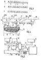
- Figure 4 shows the example of an object 13 divided into columns 10, 11, 12 each of which has a width of 32 pixels, except the last.
- the left edge of the image is indicated at 9.
- Column 10 is not used, and the address indicated in the stack P is that of the data string describing the segment which begins at point AD1. This chain is shown in Figure 3D.
- At 14 is the address of the next segment; at 15, a block of pixels is described located to the left of the point AD1 in FIG.
- the system represented by FIG. 5 is therefore organized around a topological memory 20, constituted here by two random access memory blocks, called “dynamic RAM", with a unit capacity of 16 K x 4 bits, representing four planes image using 32 K bits per plane, and shape memory 31 consisting for example of 8 K bytes of fast static RAM memory.
- This shape memory contains all the objects that can be used during a usage session, and not only those that are displayed at a given time.
- a multiplexer 25 connects on demand the links 22 between the microprocessor 33 and the modules.
- a service element 24 provides the various modules with various service signals: clock, line and frame synchronization.
- the interface module 21 ensures the loading of the memory 20 during the frame returns and its synchronous reading during the exploration of the image.
Landscapes
- Engineering & Computer Science (AREA)
- Physics & Mathematics (AREA)
- Computer Hardware Design (AREA)
- General Physics & Mathematics (AREA)
- Theoretical Computer Science (AREA)
- Controls And Circuits For Display Device (AREA)
- Image Input (AREA)
- Image Generation (AREA)
- Processing Or Creating Images (AREA)
- Digital Computer Display Output (AREA)
Applications Claiming Priority (2)
| Application Number | Priority Date | Filing Date | Title |
|---|---|---|---|
| FR8316637A FR2553918B1 (fr) | 1983-10-19 | 1983-10-19 | Procede pour engendrer des objets dans une image video |
| FR8316637 | 1983-10-19 |
Publications (3)
| Publication Number | Publication Date |
|---|---|
| EP0145046A2 true EP0145046A2 (de) | 1985-06-19 |
| EP0145046A3 EP0145046A3 (en) | 1985-07-17 |
| EP0145046B1 EP0145046B1 (de) | 1989-01-04 |
Family
ID=9293303
Family Applications (1)
| Application Number | Title | Priority Date | Filing Date |
|---|---|---|---|
| EP84201491A Expired EP0145046B1 (de) | 1983-10-19 | 1984-10-16 | Verfahren zum Generieren von Objekten in einem Videobild |
Country Status (6)
| Country | Link |
|---|---|
| US (1) | US4754966A (de) |
| EP (1) | EP0145046B1 (de) |
| JP (1) | JPS60102690A (de) |
| DE (1) | DE3475974D1 (de) |
| FR (1) | FR2553918B1 (de) |
| HK (1) | HK36492A (de) |
Cited By (5)
| Publication number | Priority date | Publication date | Assignee | Title |
|---|---|---|---|---|
| EP0268070A3 (en) * | 1986-10-15 | 1990-11-07 | Atari Games Corporation | Object processing for video system using slips and linked list |
| EP0323636A3 (de) * | 1987-12-30 | 1991-10-23 | Namco, Ltd. | System zur Anzeige von Objekten |
| EP0458692A1 (de) * | 1990-05-25 | 1991-11-27 | General Electric Cgr S.A. | Verfahren zur Anzeige eines Bildteiles einer physikalischen Struktur |
| FR2674087A1 (fr) * | 1991-03-15 | 1992-09-18 | Thomson Trt Defense | Procede et dispositif d'incrustation de reticule dans une image video. |
| US5202672A (en) * | 1987-12-30 | 1993-04-13 | Namco Ltd. | Object display system |
Families Citing this family (1)
| Publication number | Priority date | Publication date | Assignee | Title |
|---|---|---|---|---|
| US4930074A (en) * | 1986-10-15 | 1990-05-29 | Atari Games Corporation | Multiple stamp motion objects in a video game system |
Family Cites Families (5)
| Publication number | Priority date | Publication date | Assignee | Title |
|---|---|---|---|---|
| US3781850A (en) * | 1972-06-21 | 1973-12-25 | Gte Sylvania Inc | Television type display system for displaying information in the form of curves or graphs |
| US4116444A (en) * | 1976-07-16 | 1978-09-26 | Atari, Inc. | Method for generating a plurality of moving objects on a video display screen |
| US4074254A (en) * | 1976-07-22 | 1978-02-14 | International Business Machines Corporation | Xy addressable and updateable compressed video refresh buffer for digital tv display |
| FR2408262A1 (fr) * | 1977-11-03 | 1979-06-01 | Gec Computers Ltd | Appareil d'affichage a balayage par trame |
| US4498079A (en) * | 1981-08-20 | 1985-02-05 | Bally Manufacturing Corporation | Prioritized overlay of foreground objects line buffer system for a video display system |
-
1983
- 1983-10-19 FR FR8316637A patent/FR2553918B1/fr not_active Expired
-
1984
- 1984-10-16 EP EP84201491A patent/EP0145046B1/de not_active Expired
- 1984-10-16 DE DE8484201491T patent/DE3475974D1/de not_active Expired
- 1984-10-19 JP JP59218727A patent/JPS60102690A/ja active Pending
-
1986
- 1986-09-16 US US06/909,065 patent/US4754966A/en not_active Expired - Fee Related
-
1992
- 1992-05-21 HK HK364/92A patent/HK36492A/xx unknown
Cited By (6)
| Publication number | Priority date | Publication date | Assignee | Title |
|---|---|---|---|---|
| EP0268070A3 (en) * | 1986-10-15 | 1990-11-07 | Atari Games Corporation | Object processing for video system using slips and linked list |
| EP0323636A3 (de) * | 1987-12-30 | 1991-10-23 | Namco, Ltd. | System zur Anzeige von Objekten |
| US5202672A (en) * | 1987-12-30 | 1993-04-13 | Namco Ltd. | Object display system |
| EP0458692A1 (de) * | 1990-05-25 | 1991-11-27 | General Electric Cgr S.A. | Verfahren zur Anzeige eines Bildteiles einer physikalischen Struktur |
| FR2662525A1 (fr) * | 1990-05-25 | 1991-11-29 | Gen Electric Cgr | Procede de visualisation d'une partie de l'image d'une structure physique. |
| FR2674087A1 (fr) * | 1991-03-15 | 1992-09-18 | Thomson Trt Defense | Procede et dispositif d'incrustation de reticule dans une image video. |
Also Published As
| Publication number | Publication date |
|---|---|
| DE3475974D1 (en) | 1989-02-09 |
| FR2553918A1 (fr) | 1985-04-26 |
| FR2553918B1 (fr) | 1986-01-03 |
| EP0145046B1 (de) | 1989-01-04 |
| HK36492A (en) | 1992-05-29 |
| EP0145046A3 (en) | 1985-07-17 |
| JPS60102690A (ja) | 1985-06-06 |
| US4754966A (en) | 1988-07-05 |
Similar Documents
| Publication | Publication Date | Title |
|---|---|---|
| EP0171120B1 (de) | Verfahren und Vorrichtung zur Erzeugung und Veränderung von einem synthetischen Bild | |
| FR2599873A1 (fr) | Systeme d'affichage video | |
| FR2565014A1 (fr) | Systeme de memoire rapide et procede de traitement de donnees pour produire une trame d'elements d'image, et segment de memoire rapide | |
| FR2594241A1 (fr) | Processeur d'affichage de donnees sur un ecran d'affichage et procede d'affichage de donnees mettant en oeuvre ce dispositif | |
| FR2583183A1 (fr) | Procede et appareil de calcul rapide de fractals | |
| FR2554256A1 (fr) | Appareil et procede de regeneration d'un tampon de trames fonctionnant a grande vitesse | |
| FR2580840A1 (fr) | Poste d'affichage graphique video et systeme de traitement de donnees graphiques pour poste de travail de conception assistee par ordinateur | |
| FR2538588A1 (fr) | Dispositif d'affichage pour l'affichage d'informations de supports multiples d'informations | |
| FR2626402A1 (fr) | Procede et systeme pour controler ou tester fonctionnellement a grande vitesse et avec une grande precision des memoires se trouvant dans des unites a microprocesseurs | |
| FR2589601A1 (fr) | Organisation de memoire notamment pour systeme d'affichage a ordinateur et procede d'organisation | |
| EP0145046B1 (de) | Verfahren zum Generieren von Objekten in einem Videobild | |
| EP0682828B1 (de) | Verfahren und Vorrichtung zur Block Verschachtelung und Entschachtelung | |
| EP0440301B1 (de) | Abspeicherungsverfahren für die Bildverarbeitung und Gerät,um dieses einzusetzen | |
| FR2582132A1 (fr) | Circuit de memoire d'image virtuelle permettant le multifenetrage | |
| FR2618282A1 (fr) | Procedes et appareils d'emmagasinage de signaux video numeriques. | |
| FR2519456A1 (fr) | Generateur d'effets graphiques | |
| FR2589302A1 (fr) | Systeme de thermographie infrarouge a sensibilite amelioree par accumulation progressive des lignes de l'image | |
| FR2660772A1 (fr) | Procede et appareil pour produire une base de donnees a trois etats destinee a etre utilisee avec des systemes automatiques de controle optique de circuits imprimes. | |
| EP0619552B1 (de) | Verfahren und Vorrichtung zur Bestimmung von Objektbewegungen in hintereinanderfolgenden, animierten, in zweidimensionale Bildelementblöcke geteilten Bildern | |
| EP1673932B1 (de) | Steuerverfahren für eine lichtempfindliche einrichtung | |
| FR2544940A1 (fr) | Appareil de transmission de signaux video numeriques | |
| EP0716395A1 (de) | Verfahren zum Dekodieren komprimierter Bilder | |
| FR2491651A1 (fr) | Ensemble a memoire pour le transfert de donnees vers un dispositif de visualisation a tube a rayon cathodique | |
| FR2532499A1 (fr) | Dispositif et appareil de transfert d'images | |
| FR2637706A1 (fr) | Dispositif d'effacement rapide de l'ecran d'affichage d'un ordinateur, notamment pour la creation d'images animees |
Legal Events
| Date | Code | Title | Description |
|---|---|---|---|
| PUAI | Public reference made under article 153(3) epc to a published international application that has entered the european phase |
Free format text: ORIGINAL CODE: 0009012 |
|
| PUAL | Search report despatched |
Free format text: ORIGINAL CODE: 0009013 |
|
| AK | Designated contracting states |
Designated state(s): DE FR GB |
|
| AK | Designated contracting states |
Designated state(s): DE FR GB |
|
| RTI1 | Title (correction) | ||
| 17P | Request for examination filed |
Effective date: 19851220 |
|
| 17Q | First examination report despatched |
Effective date: 19871109 |
|
| RAP1 | Party data changed (applicant data changed or rights of an application transferred) |
Owner name: N.V. PHILIPS' GLOEILAMPENFABRIEKEN Owner name: LA RADIOTECHNIQUE INDUSTRIELLE ET COMMERCIALE SOCI |
|
| GRAA | (expected) grant |
Free format text: ORIGINAL CODE: 0009210 |
|
| AK | Designated contracting states |
Kind code of ref document: B1 Designated state(s): DE FR GB |
|
| REF | Corresponds to: |
Ref document number: 3475974 Country of ref document: DE Date of ref document: 19890209 |
|
| RAP4 | Party data changed (patent owner data changed or rights of a patent transferred) |
Owner name: N.V. PHILIPS' GLOEILAMPENFABRIEKEN Owner name: LA RADIOTECHNIQUE PORTENSEIGNE |
|
| GBT | Gb: translation of ep patent filed (gb section 77(6)(a)/1977) | ||
| REG | Reference to a national code |
Ref country code: FR Ref legal event code: CD |
|
| PGFP | Annual fee paid to national office [announced via postgrant information from national office to epo] |
Ref country code: FR Payment date: 19891020 Year of fee payment: 6 |
|
| PGFP | Annual fee paid to national office [announced via postgrant information from national office to epo] |
Ref country code: GB Payment date: 19891031 Year of fee payment: 6 |
|
| PLBE | No opposition filed within time limit |
Free format text: ORIGINAL CODE: 0009261 |
|
| STAA | Information on the status of an ep patent application or granted ep patent |
Free format text: STATUS: NO OPPOSITION FILED WITHIN TIME LIMIT |
|
| PGFP | Annual fee paid to national office [announced via postgrant information from national office to epo] |
Ref country code: DE Payment date: 19891215 Year of fee payment: 6 |
|
| 26N | No opposition filed | ||
| PG25 | Lapsed in a contracting state [announced via postgrant information from national office to epo] |
Ref country code: GB Effective date: 19901016 |
|
| GBPC | Gb: european patent ceased through non-payment of renewal fee | ||
| PG25 | Lapsed in a contracting state [announced via postgrant information from national office to epo] |
Ref country code: FR Effective date: 19910628 |
|
| PG25 | Lapsed in a contracting state [announced via postgrant information from national office to epo] |
Ref country code: DE Effective date: 19910702 |
|
| REG | Reference to a national code |
Ref country code: FR Ref legal event code: ST |