EP0145198B1 - Procédé de commande numérique pour un moteur et moyens - Google Patents
Procédé de commande numérique pour un moteur et moyens Download PDFInfo
- Publication number
- EP0145198B1 EP0145198B1 EP84307333A EP84307333A EP0145198B1 EP 0145198 B1 EP0145198 B1 EP 0145198B1 EP 84307333 A EP84307333 A EP 84307333A EP 84307333 A EP84307333 A EP 84307333A EP 0145198 B1 EP0145198 B1 EP 0145198B1
- Authority
- EP
- European Patent Office
- Prior art keywords
- motor
- microstepping
- mode
- phase
- phases
- Prior art date
- Legal status (The legal status is an assumption and is not a legal conclusion. Google has not performed a legal analysis and makes no representation as to the accuracy of the status listed.)
- Expired
Links
Images



Classifications
-
- H—ELECTRICITY
- H02—GENERATION; CONVERSION OR DISTRIBUTION OF ELECTRIC POWER
- H02P—CONTROL OR REGULATION OF ELECTRIC MOTORS, ELECTRIC GENERATORS OR DYNAMO-ELECTRIC CONVERTERS; CONTROLLING TRANSFORMERS, REACTORS OR CHOKE COILS
- H02P8/00—Arrangements for controlling dynamo-electric motors rotating step by step
- H02P8/22—Control of step size; Intermediate stepping, e.g. microstepping
Definitions
- This invention relates to the control of digital motors, and more particularly to the continuous control of such a motor to permit operation in a microstepping mode at low motor velocities; while, at high motor velocities, the motor can be operated in a non-microstepping mode.
- Microstepping also known as “ministep- ping”
- ministep- ping is defined as that mode of operation of a digital motor wherein the magnitudes of the currents in the various motor phases are pro- grammably adjusted in accordance with some relationship such as, in the case of a motor having two phases, the sine/cosine law.
- Non-microstepping is defined as that mode of operation of a digital motor wherein the current in any given motor phase at any given time is switched either fully on or fully off.
- microstepping to provide improved resolution in the control of digital motors is well known. It is also known that such technique can reduce motor torque to as little as about 70 percent of the torque of a digital motor operated in a non-microstepping mode. Additionally, normal microstepping requires an input pulse rate equal to the product of motor velocity times the microstepping resolution, which, at high motor velocities, requires high-speed transmission lines or shielded cables. Further, microstepping is of little value at higher motor velocities, since digital motors do not respond to high-speed current changes above a velocity of about 500 full steps per second. On the other hand, the non-microstepping mode of control offers greater torque, but also poor resolution at low motor velocities.
- U.S. 4,297,625 and WO 82/02962 each disclose an apparatus and method for operating a digital motor having a multiplicity of phases and operable in a microstepping and a non-microstepping mode.
- the apparatus comprises control means for providing pulses to the motor.
- the invention provides a method for controlling a digital motor having a multiplicity of phases and operable in both a microstepping and a nonmicrostepping mode characterised by providing energizing currents to the phases, the energizing currents having waveforms such that, at recurring times, current conditions exist simultaneously in each phase which would exist at those times in both the microstepping and the non-microstepping mode; operating the motor in a microstepping mode over a first range of motor velocities; operating the motor in a non- microstepping mode over a second range of motor velocities; and continuously switching from one stepping mode to the other at a said recurring time at a predetermined motor velocity during continuous operation of the motor.
- the invention provides apparatus for controlling a digital motor having a multiplicity of phases operable in both a microstepping mode and a non-microstepping mode comprising; control means for providing pulses to the motor and characterised by translator means arranged to provide control signals to the control means in response to input commands such that energizing currents provided to the phases have waveforms such that, at recurring times current conditions exist simultaneously in each phase which are identical to current conditions which would exist in both the microstepping and the non-microstepping mode, such that the motor may be operated in a microstepping mode over a first range of motor velocities and operated in a non-microstepping mode over a second range of velocities; and wherein the translator means causes the motor to switch from one stepping mode to the other at a said recurring time at a predetermined velocity during continuous operation of the motor.
- a motor may be operated in a microstepping mode at low motor velocities, where high resolution is important; then, when the motor velocity reaches a predetermined value, the control mode can be switched to non-microstepping to obtain increased torque, the transition being achieved without introducing undesirable velocity perturbations.
- the transition velocity may be chosen at a value low enough that the use of high-speed transmission lines or shielded cables is unnecessary.
- a digital motor drive in accordance with the present invention is generally indicated by the reference numeral 10 and includes a microstepping translator 11 which provides control signals to a digital motor control 12 which provides driving pulses to a digital motor 13.
- Command inputs to the translator 11 include a step size input register 14 into which is entered step size, e.g., 1/128 (equivalent to 128 microsteps per full step).
- step size e.g., 1/128 (equivalent to 128 microsteps per full step).
- the number of steps per unit time is entered into a velocity input register 15 and the number of microsteps to be taken is entered into a pulse count input register 16.
- Direction of movement and time of initiation of movement are entered into a control input register 17.
- a handshaking signals register 18 may be included to confirm that the translator 11 has received the inputs from the other registers 15, 16, 17, and 18, which registers may be set manually or by mechanical or electrical/electronic means.
- a feedback stabilising pulse from the motor phase drive 13 to the translator 11 may be included as an input on a lead 19 to a stabilising circuit in the translator 11, such as described in U.S. Patent 4,220,904, assigned to the present Applicant.
- a stabilising circuit in the translator 11, such as described in U.S. Patent 4,220,904, assigned to the present Applicant.
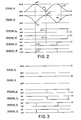
- curves (a) and (b) show the current flowing as a function of time, in a conventional microstepping mode, through the two phases, here referred to as Phase A and Phase B, which approximate sine waves displaced by 90 electrical degrees to produce torque.
- the curves (a) and (b) are not smooth as shown, but comprise sawtoothed microsteps, the number of which per full motor step depends on the degree of microstepping desired, but typically range up to 128 microsteps per full step, although there is no upper limit relative to the present invention.
- Curves (c) and (d) show the on/ off conditions of the windings associated with Phase A, here designated as Winding A and A'; and curves (e) and (f) show the on/off conditions of the Windings associated with phase B, here designated as Winding B and Winding B'.
- Each phase is in a microstepping mode at all times and switching of the windings in a phase takes place when the current in, that phase is zero. For example, when the current in Phase B is zero, as at point b1 on curve (b), Winding B is switched from on to off at point e1 on curve (e), and Winding B' is switched from off to on at point f1 on curve (f). Similarly, when the current in Phase A is zero, as at point a1 on curve (a), Winding A is switched from off to on at point c1 on curve (c), and Winding A' is switched from on to off at point d1 on curve (d).
- the curves are designated similarly to those in Figure 2, except that, in this case, the motor is operating in a non-microstepping mode, specifically a full-stepping, two-windings-on mode, with maximum current in each winding at all times.
- the current in the windings is switched to produce on/off condition waveforms, curves (c), (d), (e), and (f), identical to the respective waveforms on Figure 2; however, it will be recognized that the operating mode represented by Figure 3 will produce greater torque than that represented by Figure 2, due to the higher phase currents.
- phase current and winding on/off condition waveforms are shown for the present invention in its microstepping mode and are designated as for similar waveforms on Figures 2 and 3.
- Curves (a) and (b) of Figure 4 differ significantly from curves (a) and (b) of Figure 2 in that the phase currents in the present invention are not microstepped at all times. Rather, one phase is held at maximum current while the other phase is microstepped and these roles are alternately reversed.
- Phase A is held at maximum current from point a1 to point a2 while over the same period of time
- Phase B is microsteped from point b1 to point b2, the latter points corresponding in time with points a1 and a2, respectively.
- Phase B is held at maximum current from point b2 to point b3 while Phase A is microstepped from point a2 to point a3, the latter points corresponding in time with points b2 and b3, respectively.
- switching of the windings in a phase occurs when the current in that phase is zero.
- the phase A current is zero, as at point a5 on Figure 4, Winding A is switched from off to on at point c1, and Winding A' is switched from on to off at point d1.
- winding on/off condition waveforms are the same for both the conventional and the new microstepping.
- the new microstepping of the present invention provides points in time or "synchronizing edges" at which transition from microstepping to full-stepping or from full-stepping to microstepping may be accomplished without causing a disturbance in either phase, since the currents in the phases are identical to those in either stepping mode.
- One synchronizing edge occurs, for example, at the time corresponding to points a1 and b1 on Figure 4.
- similar synchronizing edges occur at the times corresponding to the pairs of points a2 and b2, a3 and b3, and a4 and b4. At these times, both phases are at maximum current and, therefore, a transition between stepping modes will not cause a disturbance.
- phase A will commence the microstepping sequence and at the end of one microstep cycle, corresponding to points a2 and b1, phase B will commence microstepping.
- Transition to microstepping from non- microstepping or to non-microstepping from microstepping is not limited to the case when the non-microstepping mode is a full-stepping mode, as has been described above.
- the invention may be employed when the non-microstepping mode is any, within the capability of the digital motor.
- the two-phase, four-winding digital motor under consideration may be operated in one other non-microstepping mode, namely, a half-stepping mode.
- Figure 7 shows the phase current and winding on/off condition waveforms for such a motor driven in a half stepping mode.
- the waveforms are similar to those for full- stepping shown on Figure 3, except that the winding on/off condition waveforms for half-stepping show the characteristic one-on/two-on/ one-on stepwise sequence of winding energization.
- FIG. 8 shows the phase current waveforms for the transition from microstepping to half-stepping at the points a1 and b1, corresponding in time to points c1, d1, e1 and f1 on Figure 7
- Phase A ( Figure 8) remains at maximum current
- Phase B has reached maximum current and will remain at that level
- the windings are in the two-on condition of half-stepping ( Figure 7) and will subsequently follow the half-stepping pattern shown.
- transition from half-stepping to microstepping could take place at point a1 on Figure 9, also corresponding in time to points c1, d1, e1, and f1 on Figure 7.
- phase A ( Figure 9) would commence microstepping and Windings A and A' would start to be switched in the pattern shown on Figure 4.
- Phase B would commence microstepping and its windings would also start to be switched in the pattern shown on Figure 4.
- Curve (a) represents, for the motor described above, torque as a function of motor velocity for conventional microstepping, while curves (b) and (c) represent similar relationships, respectively, for full-stepping and the present invention.
- the segment of curve (c) between points c1 and c2 represents the microstepping mode of the invention, while the vertical segment between points c2 and c3 represents the transition point.
- the motor is operated in non-microstepping mode.
- the torque produced with conventional microstepping is about 70 percent of the torque produced with full-stepping.
- the half-stepping mode torque is approximately 85-90 percent of the full-stepping mode torque. Over the microstepping range of the present invention, the torque produced is about 85 percent of full-stepping, since there is at all times at least one phase that is at maximum current.
- full torgue is, of course, obtained.
- transition might desirably take place when the motor velocity is on the order of 500 full steps per second, since microstepping is of little value at higher motor velocities and high-speed transmission lines and shielded cables can be avoided if the transition is made at that velocity.
- the transition may be made at any predetermined velocity.
- the number of microsteps per full step may be successively reduced as motor velocity increases in the microstepping range.
Landscapes
- Engineering & Computer Science (AREA)
- Power Engineering (AREA)
- Control Of Stepping Motors (AREA)
Claims (9)
Applications Claiming Priority (2)
| Application Number | Priority Date | Filing Date | Title |
|---|---|---|---|
| US06/549,438 US4518907A (en) | 1983-11-07 | 1983-11-07 | Digital motor control method and means |
| US549438 | 1983-11-07 |
Publications (2)
| Publication Number | Publication Date |
|---|---|
| EP0145198A1 EP0145198A1 (fr) | 1985-06-19 |
| EP0145198B1 true EP0145198B1 (fr) | 1990-02-28 |
Family
ID=24193035
Family Applications (1)
| Application Number | Title | Priority Date | Filing Date |
|---|---|---|---|
| EP84307333A Expired EP0145198B1 (fr) | 1983-11-07 | 1984-10-25 | Procédé de commande numérique pour un moteur et moyens |
Country Status (3)
| Country | Link |
|---|---|
| US (1) | US4518907A (fr) |
| EP (1) | EP0145198B1 (fr) |
| DE (1) | DE3481470D1 (fr) |
Families Citing this family (20)
| Publication number | Priority date | Publication date | Assignee | Title |
|---|---|---|---|---|
| JPH088796B2 (ja) * | 1986-07-24 | 1996-01-29 | 武藤工業株式会社 | ステッピングモーターのマイクロステップ駆動方法 |
| JPH0681229B2 (ja) * | 1987-08-24 | 1994-10-12 | コニカ株式会社 | 画像読取装置 |
| US4855660A (en) * | 1988-02-18 | 1989-08-08 | Siemens-Bendix Automotive Electronics L.P. | Microstepping of an unipolar stepping motor |
| US4884016A (en) * | 1988-08-23 | 1989-11-28 | Aerotech, Inc. | Closed loop torque angle control of synchronous motor |
| WO1994008279A1 (fr) * | 1992-09-29 | 1994-04-14 | Siemens Aktiengesellschaft | Procede de commande d'un moteur pas-a-pas |
| US5650705A (en) * | 1995-02-13 | 1997-07-22 | Hart; John Roger | Apparatus and method for controlling currents in an inductor |
| US6016044A (en) | 1995-09-11 | 2000-01-18 | Alaris Medical Systems, Inc. | Open-loop step motor control system |
| KR100217789B1 (ko) * | 1996-05-22 | 1999-09-01 | 가타오카 마사타카 | 스테핑모터의 구동방법 |
| US5914579A (en) * | 1997-10-02 | 1999-06-22 | Dana Corporation | Direct current command generation for a stepper motor drive |
| US6121745A (en) * | 1997-10-02 | 2000-09-19 | Warner Electric Technology, Inc. | Direct current command generation for a stepper motor drive |
| US5904789A (en) * | 1997-11-24 | 1999-05-18 | Imaginal Systematics, L.L.C. | Box spring stapler apparatus and method |
| US6713985B2 (en) * | 2000-03-31 | 2004-03-30 | Canon Kabushiki Kaisha | Drive control apparatus for stepping motor |
| JP4261752B2 (ja) | 2000-09-07 | 2009-04-30 | キヤノン株式会社 | 駆動装置 |
| US6935546B2 (en) * | 2001-11-29 | 2005-08-30 | Imaginal Systematics, Llc | Box spring stapler apparatus |
| US7222402B1 (en) | 2001-11-29 | 2007-05-29 | Imaginal Systematics, Llc | Box spring stapler apparatus |
| KR100449715B1 (ko) * | 2002-01-23 | 2004-09-22 | 삼성전자주식회사 | 스텝 모터 구동방법 |
| KR100555556B1 (ko) * | 2004-02-10 | 2006-03-03 | 삼성전자주식회사 | 스테핑 모터 제어 방법 |
| US7516533B2 (en) * | 2004-04-09 | 2009-04-14 | L&P Property Management Company | Positioning device for staple guns and method of use |
| US7490401B2 (en) * | 2004-04-09 | 2009-02-17 | L&P Property Management Company | Positioning device for staple guns and method of use |
| US10171701B2 (en) * | 2017-04-13 | 2019-01-01 | Microtek International Inc. | Image scanning apparatus |
Family Cites Families (4)
| Publication number | Priority date | Publication date | Assignee | Title |
|---|---|---|---|---|
| US4297625A (en) * | 1979-04-09 | 1981-10-27 | Mesur-Matic Electronics Corporation | Apparatus for dividing the step angle of a stepping motor |
| US4409534A (en) * | 1980-04-09 | 1983-10-11 | General Electric Company | Microcomputer-based pulse width modulated inverter fed machine drive system |
| US4377847A (en) * | 1981-02-17 | 1983-03-22 | Gould Inc. | Microprocessor controlled micro-stepping chart drive |
| US4453188A (en) * | 1981-04-10 | 1984-06-05 | Amlyn Corporation | Disk drive |
-
1983
- 1983-11-07 US US06/549,438 patent/US4518907A/en not_active Expired - Lifetime
-
1984
- 1984-10-25 DE DE8484307333T patent/DE3481470D1/de not_active Expired - Lifetime
- 1984-10-25 EP EP84307333A patent/EP0145198B1/fr not_active Expired
Also Published As
| Publication number | Publication date |
|---|---|
| DE3481470D1 (de) | 1990-04-05 |
| US4518907A (en) | 1985-05-21 |
| EP0145198A1 (fr) | 1985-06-19 |
Similar Documents
| Publication | Publication Date | Title |
|---|---|---|
| EP0145198B1 (fr) | Procédé de commande numérique pour un moteur et moyens | |
| EP0321473B1 (fr) | Systeme permettant de reguler les multiples secondaires synchrones d'un moteur lineaire le long d'un cheminement allonge | |
| SU552913A3 (ru) | Устройство дл управлени шаговым двигателем | |
| US4463301A (en) | Step motor driving circuit | |
| EP0559464B1 (fr) | Méthode et procédé pour commander en circuit fermé l'accélération et la vitesse d'un moteur pas à pas | |
| US5008607A (en) | Driving system for stepping motor | |
| EP0053684A2 (fr) | Entraînement par moteur pas à pas et imprimante le contenant | |
| US4443746A (en) | Control circuit for stepping motor | |
| US4470001A (en) | Induction motor control | |
| EP0431731B1 (fr) | Compensation de friction pour commande de vitesse d'une masse | |
| JP3259441B2 (ja) | 誘導電動機のベクトル制御装置 | |
| EP0247338B1 (fr) | Mécanisme pour positioner un membre de sortie | |
| US5844393A (en) | Stepper drive control using variable step angle | |
| EP0304704A1 (fr) | Méthode et dispositif pour la commande d'un moteur pas à pas par plusieurs tensions | |
| JPH0317594Y2 (fr) | ||
| JP2769721B2 (ja) | ディスク装置のステッピングモータ駆動方法 | |
| JP2738163B2 (ja) | サーボモータ運転方法 | |
| GB2045021A (en) | Drive system with a two-phase synchronous motor | |
| EP0220814A2 (fr) | Dispositif et méthode de stabilisation pour moteur pas à pas | |
| JPH0759398A (ja) | ステッピングモータの駆動方式 | |
| JPS60257272A (ja) | 印刷キヤリア装置の水平移動制御装置 | |
| JPH0332391A (ja) | 可変速交流電動機用pwm形インバータのパルス制御装置 | |
| SU957172A1 (ru) | Устройство дл программного управлени шаговым двигателем | |
| RU2020725C1 (ru) | Способ программного позиционного управления многофазным шаговым электродвигателем с электрическим дроблением шага | |
| GB2332309A (en) | Stepper motor controller |
Legal Events
| Date | Code | Title | Description |
|---|---|---|---|
| PUAI | Public reference made under article 153(3) epc to a published international application that has entered the european phase |
Free format text: ORIGINAL CODE: 0009012 |
|
| AK | Designated contracting states |
Designated state(s): DE FR GB IT |
|
| 17P | Request for examination filed |
Effective date: 19851024 |
|
| 17Q | First examination report despatched |
Effective date: 19870219 |
|
| GRAA | (expected) grant |
Free format text: ORIGINAL CODE: 0009210 |
|
| AK | Designated contracting states |
Kind code of ref document: B1 Designated state(s): DE FR GB IT |
|
| ITF | It: translation for a ep patent filed | ||
| ET | Fr: translation filed | ||
| REF | Corresponds to: |
Ref document number: 3481470 Country of ref document: DE Date of ref document: 19900405 |
|
| PLBE | No opposition filed within time limit |
Free format text: ORIGINAL CODE: 0009261 |
|
| STAA | Information on the status of an ep patent application or granted ep patent |
Free format text: STATUS: NO OPPOSITION FILED WITHIN TIME LIMIT |
|
| 26N | No opposition filed | ||
| ITTA | It: last paid annual fee | ||
| REG | Reference to a national code |
Ref country code: GB Ref legal event code: 732E |
|
| REG | Reference to a national code |
Ref country code: FR Ref legal event code: TP |
|
| PGFP | Annual fee paid to national office [announced via postgrant information from national office to epo] |
Ref country code: FR Payment date: 20001002 Year of fee payment: 17 |
|
| PGFP | Annual fee paid to national office [announced via postgrant information from national office to epo] |
Ref country code: DE Payment date: 20001003 Year of fee payment: 17 |
|
| PGFP | Annual fee paid to national office [announced via postgrant information from national office to epo] |
Ref country code: GB Payment date: 20001004 Year of fee payment: 17 |
|
| PG25 | Lapsed in a contracting state [announced via postgrant information from national office to epo] |
Ref country code: GB Free format text: LAPSE BECAUSE OF NON-PAYMENT OF DUE FEES Effective date: 20011025 |
|
| REG | Reference to a national code |
Ref country code: GB Ref legal event code: IF02 |
|
| GBPC | Gb: european patent ceased through non-payment of renewal fee |
Effective date: 20011025 |
|
| PG25 | Lapsed in a contracting state [announced via postgrant information from national office to epo] |
Ref country code: FR Free format text: LAPSE BECAUSE OF NON-PAYMENT OF DUE FEES Effective date: 20020628 |
|
| PG25 | Lapsed in a contracting state [announced via postgrant information from national office to epo] |
Ref country code: DE Free format text: LAPSE BECAUSE OF NON-PAYMENT OF DUE FEES Effective date: 20020702 |
|
| REG | Reference to a national code |
Ref country code: FR Ref legal event code: ST |