EP0145237B1 - Samenausgabemechanismus - Google Patents
Samenausgabemechanismus Download PDFInfo
- Publication number
- EP0145237B1 EP0145237B1 EP84307561A EP84307561A EP0145237B1 EP 0145237 B1 EP0145237 B1 EP 0145237B1 EP 84307561 A EP84307561 A EP 84307561A EP 84307561 A EP84307561 A EP 84307561A EP 0145237 B1 EP0145237 B1 EP 0145237B1
- Authority
- EP
- European Patent Office
- Prior art keywords
- seed
- disc
- plate
- seed selection
- apertures
- Prior art date
- Legal status (The legal status is an assumption and is not a legal conclusion. Google has not performed a legal analysis and makes no representation as to the accuracy of the status listed.)
- Expired
Links
- 230000007246 mechanism Effects 0.000 title claims description 47
- 238000007789 sealing Methods 0.000 claims description 14
- 238000004519 manufacturing process Methods 0.000 claims description 8
- 229910001220 stainless steel Inorganic materials 0.000 claims description 8
- 239000010935 stainless steel Substances 0.000 claims description 8
- 239000000463 material Substances 0.000 claims description 6
- 230000009471 action Effects 0.000 claims description 5
- 238000003486 chemical etching Methods 0.000 claims description 5
- 230000000694 effects Effects 0.000 claims description 5
- 238000000034 method Methods 0.000 claims description 5
- 238000005530 etching Methods 0.000 claims description 4
- 239000007769 metal material Substances 0.000 claims description 4
- 238000005260 corrosion Methods 0.000 claims description 3
- 230000007797 corrosion Effects 0.000 claims description 3
- 229910021578 Iron(III) chloride Inorganic materials 0.000 claims description 2
- RBTARNINKXHZNM-UHFFFAOYSA-K iron trichloride Chemical compound Cl[Fe](Cl)Cl RBTARNINKXHZNM-UHFFFAOYSA-K 0.000 claims description 2
- 230000000873 masking effect Effects 0.000 claims 2
- 238000012423 maintenance Methods 0.000 description 3
- 239000002689 soil Substances 0.000 description 3
- OKTJSMMVPCPJKN-UHFFFAOYSA-N Carbon Chemical compound [C] OKTJSMMVPCPJKN-UHFFFAOYSA-N 0.000 description 2
- 230000015572 biosynthetic process Effects 0.000 description 2
- 238000005755 formation reaction Methods 0.000 description 2
- 230000001788 irregular Effects 0.000 description 2
- 230000009467 reduction Effects 0.000 description 2
- 235000013311 vegetables Nutrition 0.000 description 2
- 244000291564 Allium cepa Species 0.000 description 1
- 235000002732 Allium cepa var. cepa Nutrition 0.000 description 1
- 241000219310 Beta vulgaris subsp. vulgaris Species 0.000 description 1
- 244000000626 Daucus carota Species 0.000 description 1
- 235000002767 Daucus carota Nutrition 0.000 description 1
- 240000005979 Hordeum vulgare Species 0.000 description 1
- 235000007340 Hordeum vulgare Nutrition 0.000 description 1
- 240000008415 Lactuca sativa Species 0.000 description 1
- 235000003228 Lactuca sativa Nutrition 0.000 description 1
- 239000004677 Nylon Substances 0.000 description 1
- 235000010627 Phaseolus vulgaris Nutrition 0.000 description 1
- 244000046052 Phaseolus vulgaris Species 0.000 description 1
- 235000021536 Sugar beet Nutrition 0.000 description 1
- 235000021307 Triticum Nutrition 0.000 description 1
- 244000098338 Triticum aestivum Species 0.000 description 1
- 239000004411 aluminium Substances 0.000 description 1
- 229910052782 aluminium Inorganic materials 0.000 description 1
- XAGFODPZIPBFFR-UHFFFAOYSA-N aluminium Chemical compound [Al] XAGFODPZIPBFFR-UHFFFAOYSA-N 0.000 description 1
- 229910052799 carbon Inorganic materials 0.000 description 1
- 238000005266 casting Methods 0.000 description 1
- 235000013339 cereals Nutrition 0.000 description 1
- 238000004140 cleaning Methods 0.000 description 1
- 238000010276 construction Methods 0.000 description 1
- 238000005553 drilling Methods 0.000 description 1
- 230000005611 electricity Effects 0.000 description 1
- 229910002804 graphite Inorganic materials 0.000 description 1
- 239000010439 graphite Substances 0.000 description 1
- 230000005484 gravity Effects 0.000 description 1
- 230000001050 lubricating effect Effects 0.000 description 1
- 230000014759 maintenance of location Effects 0.000 description 1
- 238000010297 mechanical methods and process Methods 0.000 description 1
- 230000005226 mechanical processes and functions Effects 0.000 description 1
- 239000002184 metal Substances 0.000 description 1
- 229910052751 metal Inorganic materials 0.000 description 1
- 150000002739 metals Chemical class 0.000 description 1
- 238000012986 modification Methods 0.000 description 1
- 230000004048 modification Effects 0.000 description 1
- 238000010137 moulding (plastic) Methods 0.000 description 1
- 229920001778 nylon Polymers 0.000 description 1
- 238000005498 polishing Methods 0.000 description 1
- -1 polytetrafluoroethylene Polymers 0.000 description 1
- 229920001343 polytetrafluoroethylene Polymers 0.000 description 1
- 239000004810 polytetrafluoroethylene Substances 0.000 description 1
- 230000008569 process Effects 0.000 description 1
- 238000009331 sowing Methods 0.000 description 1
- 238000005507 spraying Methods 0.000 description 1
- 230000003068 static effect Effects 0.000 description 1
Images

Classifications
-
- A—HUMAN NECESSITIES
- A01—AGRICULTURE; FORESTRY; ANIMAL HUSBANDRY; HUNTING; TRAPPING; FISHING
- A01C—PLANTING; SOWING; FERTILISING
- A01C7/00—Sowing
- A01C7/04—Single-grain seeders with or without suction devices
- A01C7/042—Single-grain seeders with or without suction devices using pneumatic means
- A01C7/044—Pneumatic seed wheels
- A01C7/046—Pneumatic seed wheels with perforated seeding discs
-
- A—HUMAN NECESSITIES
- A01—AGRICULTURE; FORESTRY; ANIMAL HUSBANDRY; HUNTING; TRAPPING; FISHING
- A01C—PLANTING; SOWING; FERTILISING
- A01C7/00—Sowing
- A01C7/04—Single-grain seeders with or without suction devices
- A01C7/042—Single-grain seeders with or without suction devices using pneumatic means
- A01C7/044—Pneumatic seed wheels
- A01C7/0443—Seed singulators
-
- A—HUMAN NECESSITIES
- A01—AGRICULTURE; FORESTRY; ANIMAL HUSBANDRY; HUNTING; TRAPPING; FISHING
- A01C—PLANTING; SOWING; FERTILISING
- A01C7/00—Sowing
- A01C7/04—Single-grain seeders with or without suction devices
- A01C7/042—Single-grain seeders with or without suction devices using pneumatic means
- A01C7/044—Pneumatic seed wheels
- A01C7/0445—Seed ejectors
Definitions
- This invention relates to seed dispensing mechanisms.
- the invention relates to such mechanisms for use in precision planters in which seeds are selected and dispensed individually as opposed to seed dispensing mechanisms in which the rate of dispensing is controlled by varying the flow of seed.
- precision-type dispensing mechanisms are used for dispensing seeds in drills and planters for such row crops as small bean and vegetable seeds, and natural or pelleted sugar beet, as opposed to such cereal seeds as wheat, barley and the like which are usually dispensed in a less precise way.
- the invention relates to seed dispensing mechanisms employing a pressure differential to cause seeds to be held to a series of seed apertures in a rotary member such as a plate or disc.
- a vacuum is applied to one side of the disc and the seeds are held against the apertures on the other side of the disc by the atmospheric air pressure.
- the disc is rotated, seeds are picked up from a seed reservoir by the apertures in the disc, excess seeds are singulated and the individual seeds remaining on the disc are then dispensed one at a time at a discharge point located on the path of travel of the seed apertures after singulation has taken place and before the apertures re-enter the reservoir.
- one particular problem relates to maintenance of the vacuum or pressure differential.
- the sealing arrangement between the disc and its housing must be effective to allow the maintenance of a steady and adequate vacuum on the relevant side of the disc. Irregularities in the sealing arrangement will give rise to reduction of the vacuum and interference with the seed selection. Localised sealing failures, although perhaps within the capacity of the vacuum pump so far as concerns maintenance of the overall vacuum, can cause localised variations in the vacuum whereby seed selection becomes irregular.
- DE-U-7 231 803 discloses a seed dispensing mechanism as defined in the precharacterizing portion of claim 1 hereof.
- An aim of the present invention is to provide a seed selection plate or disc and a seed dispensing mechanism incorporating same in which at least one of the problems identified above is alleviated or overcome.
- One aspect of the invention as provided in an embodiment described below includes a seed selection plate or disc for sealing engagement with a support having a generally flat surface in a differential pressure seed selection mechanism, the plate having spaced seed selection apertures formed therein, wherein the plate is flexible to the extent that the plate deforms under the pneumatic pressure differential applied thereto so as to provide a self sealing effect with respect to said support therefor.
- a seed selection plate for a differential pressure seed selection mechanism having spaced seed selection apertures formed therein, wherein the thickness of the plate lies in the range of 0.125 to 0.625 millimetres.
- the plate preferably comprises a metallic material such as stainless steel.
- a further aspect of the invention as provided in an embodiment described below is a seed selection plate for a differential pressure seed selection mechanism, the plate having spaced seed selection apertures formed therein, wherein the plate is formed with said seed apertures by a non-mechanical means such as chemical etching.
- a seed selection plate for a differential pressure seed selection mechanism the plate having spaced seed selection apertures formed therein, wherein the seed selection plate comprises stainless steel having a thickness between 0.125 millimetres and 0.625 millimetres and a flexibility such that the plate deforms under the pneumatic pressure differential applied thereto to provide a degree of self sealing, the plate having said seed apertures formed therein by non-mechanical means such as chemical etching.
- the seed selection plate comprises stainless steel of thickness between 0.2 and 0.3 millimetres.
- a single row of circumferentially spaced seed apertures may be formed in the selection plate.
- two radially spaced rows or three radially spaced rows of such seed apertures may be formed in the plate.
- a seed dispensing mechanism for an agricultural precision drill or planter having the features of claim 5.
- support means for the plate and engageable therewith on the vacuum side thereof may be provided.
- the support means may comprise a circumferentially extending rib having a flat upper surface for engagement with the plate.
- the plate may be supported at or in the region of its outer periphery on an outer circumferentially extending support member formed with a flat surface for engagement with the plate.
- a further circumferentially extending support member or rib may be provided radially inwardly of the outer support member.
- Corresponding support members may be provided between the rows of seed selection apertures.
- the plate support members may be mounted on a housing member having connection means thereto whereby said differential pressure may be set up across the plate.
- a central turntable may be provided to support the inner region of the seed selection plate.
- Drive formations are preferably provided on the turntable for driving engagement with the plate.
- a blanking member is preferably provided for engagement with the disc to blank-off the seed apertures on the vacuum side whereby the seeds may be discharged.
- Seed discharge means is preferably also provided to dislodge the seeds. The seed discharge means may provide for an air flow through the seed apertures from the vacuum side of the discs to the other side to dislodge the seeds.
- a method of making a seed selection plate comprising the features of claim 11 is a further aspect of the invention.
- Figs. 1 to 8 show a seed dispensing mechanism 10 which forms part of a row unit (not shown) of a precision planter (not shown).
- the planter is of the kind comprising a transversely extending toolbar adapted to be mounted on the hitch links of an agricultural tractor and having laterally spaced row units mounted at intervals along its length, each row unit having its own seed hopper, seed dispensing mechanism and coulter assembly and press wheel. Seeds from the seed hopper of each row unit are selected one at a time by the dispensing mechanism and dropped into a furrow opened by the coulter assembly, the furrow is then closed and the soil is pressed down by the press wheel.
- Such planters are used for sowing carrots, onions, lettuces and other small vegetable seeds.
- a seed dispensing mechanism 10 has its own seed reservoir and discharges selected seeds into a discharge assembly (not shown) very close to the soil-opening coulter.
- the dispensing mechanism 10 is mounted at about 3.8 centimetres clearance from the ground whereby the seeds are discharged very close to the furrow and there is very little loss of accuracy between the dispensing mechanism and the soil itself.
- the direction of rotation of the seed selection plate (described below) of the dispensing mechanism is such that the seed is dispensed with a velocity in the opposite direction to the ground speed of the implement whereby the net velocity of the seed with respect to the ground is very low.
- Seed dispensing mechanism 10 broadly comprises a housing 12, a seed reservoir 14, a drive 16, a seed selection plate 18, a seed singulation mechanism 20, and seed ejection means 22.
- Housing 12 is formed as an aluminium casting and comprises a vacuum side body member 24 and a seed side body member 26 detachably secured together by means of releasable fasteners at 28, 30 and having a connection pipe (not shown) on body member 24 whereby a hose is connected thereto from a vacuum pump driven by the tractor's p.t.o. (or by a hydraulic drive or other power source) and effective to lower the pressure between plate 18 and body member 24.
- Housing 12 could alternatively be formed as a plastic moulding e.g. of nylon or the like.
- Seed reservoir 14 is generally wedge-shaped and funnels seed down to the seed dispensing mechanism and to seed selection plate 18 in particular and is formed integrally with housing 12. Seed selection takes place in a seed selection zone 32 through which apertures 34 in selection plate 18 pass, to pick-up seeds.
- Drive 16 comprises a pulley 36 driven by a belt (not shown) from a ground wheel or press wheel so as to rotate at a speed directly related to the ground speed of the planter or drill.
- the drive rotates seed selection plate 18 and associated components described below.
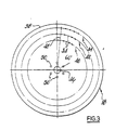
- Seed selection plate 18 is shown in Fig. 3 and is in the form of a circular disc formed of grade 301 hard rolled stainless steel sheet of thickness 0.254 millimetres.
- the disc is of diameter 207 millimetres and is formed with three rows 40,42,44 of seed apertures 34 arranged coaxially with plate 18 (axis 46) and of diameters 190 and 162 and 134 millimetres respectively.
- Each row 40, 42 and 44 of apertures 34 comprises sixty apertures spaced at six degree intervals around the circumference of the disc so that the apertures on the three rows are arranged in radially aligned groups as indicated by reference radius 48. It is to be understood that such an arrangement of the apertures is by no means essential.
- the seed apertures 34 are each circular in shape and of diameter 0.5 millimetres and formed by a non-mechanical process of chemical etching.
- the etching is effected by spraying ferric chloride onto both sides of plate 18 after the latter has been appropriately masked by a photographic process so that only the desired apertures are etched. It is to be noted that the plate 18 is rolled as flat as possible prior to etching.
- a series of six drive apertures 50 are formed in the central region of plate 18 to receive six corresponding drive pins 52 projecting axially from a turntable 54 driven by pulley 36 and serving to support the central region of plate 18.
- seed agitator means comprising a shaft 66 rotated by drive pins 52 through a paddle wheel 68.
- the shaft carries agitator pins 70 to agitate the seed in the seed selection zone 32.
- Shaft 66 extends radially of seed selection plate 18 and pins 70 are mounted thereon by hubs 71.
- Drive apertures 50 which receive drive pins 52 are located at angular spacings of 60 degrees and thus there is a considerable amount of lost motion in the drive to shaft 66 whereby agitating pins 70 have an irregular circular motion which serves to provide a particularly effective agitating action.
- Seed singulation mechanism 20 comprises adjustable mechanical means to doff or remove excess seeds from the rows of apertures 40, 42, 44 and thus leave, as far as possible, a single seed in each aperture 34.
- a manual adjustment knob 72 actuates singulator members (not shown) arranged in pairs so that the rows 40, 42 and 44 of apertures 34 can pass between the members of each pair. Adjustment of knob 72 causes the singulator members of each pair to move towards or away from its row of seed selection apertures.
- the seed ejection means 22 comprises a vacuum cut off plate 106 against which the vacuum side of plate 18 runs, whereby the seeds are no longer held by the vacuum. This causes the seeds to fall from the plate by gravity.
- seed reservoir 14 is full of seed and drive 16 rotates seed selection plate 18 about axis 46 in the clockwise direction as seen in Fig. 1.
- Seed is picked up at seed selection zone 32, excess seeds are doffed by singulation mechanism 20 and the seeds are dispensed one-by-one at cut off plate 22 straight into the furrow opened by the coulter (not shown).
- the arrangement is such that the seeds from each of the rows 40, 42, 44 of apertures are delivered to individual furrows in the soil.
- seed selection plate 18 is of thickness only 0.254 millimetres as compared with the conventional disc thickness of 1.55 millimetres, it is very much more flexible than a conventional seed selection disc and is deformed by the vacuum applied to the vacuum side of the disc so as to effect a degree of self-sealing with respect to the circular support ribs 60, 62 and 64 and the outer periphery of turntable 54.
- the outer portion of plate 18 together with the turntable and the ribs and the vacuum side body member 24 form a substantially airtight vacuum chamber from which air is evacuated by the vacuum pump and to which, to a first approximation, air can only be admitted through the apertures 34.
- the vacuum applied to plate 18 is easily maintained, is substantially constant around the whole circumference of the apparatus and is mainly unaffected by minor irregularities in the housing.
- the seed selection apertures 34 themselves, these are particularly smooth and regular with no burrs, swarf or other irregularities to interfere with the selection and retention of seeds.
- the apertures are formed chemically whereby each aperture has a smooth rounded profile. Moreover, no mechanical action is involved in the formation of the apertures and hence no corresponding distortion of the disc occurs.
- Singulation mechanism 20 is adjusted by means of knob 72 to achieve the maximum singulation effect.
- the throat defined by the two singulation members of each pair By adjusting the throat defined by the two singulation members of each pair, the point can be reached where all the excess seeds from a high proportion of the apertures 34 are removed before the seeds reach the seed release zone.
- the diameter of the plate is chosen to suit the size of the dispensing apparatus.
- One, two, three or more rows of seed apertures can be provided in it.
- the spacing of the rows and the spacing of the apertures in each row can be varied according to the seed requirements.
- the apertures need not be radially aligned.
- the size of each aperture can likewise be varied to suit the seed.
- stainless steel is preferred in that it has good corrosion resistance and static electricity effects are avoided.
- the range of thickness of the disc, measured between its opposite sides, so far as metals such as stainless steel are concerned is from 0.125 to 0.625 millimetres with the range of 0.2 to 0.3 millimetres being preferred.
- the invention may also be adapted for use with seed selection mechanisms whereby the pressure differential is generated by raising the pressure on the seed side of the disc to above atmospheric pressure.
- more than one singulator or member may be provided on each side of each row and other shapes of singulator member may be adopted.
- ulation as used in this specification it is to be understood that the term does not necessarily refer to the production of the optimum situation where only one seed remains in each seed selection aperture. This result depends very much on the careful adjustment of the mechanism. Accordingly, the term “singulation” is intended to refer to the reduction in the number of "doubles” and “triples” in the seed apertures.
Landscapes
- Life Sciences & Earth Sciences (AREA)
- Soil Sciences (AREA)
- Environmental Sciences (AREA)
- Pretreatment Of Seeds And Plants (AREA)
Claims (12)
Applications Claiming Priority (2)
| Application Number | Priority Date | Filing Date | Title |
|---|---|---|---|
| GB838330850A GB8330850D0 (en) | 1983-11-18 | 1983-11-18 | Seed dispensing mechanisms |
| GB8330850 | 1983-11-18 |
Publications (2)
| Publication Number | Publication Date |
|---|---|
| EP0145237A1 EP0145237A1 (de) | 1985-06-19 |
| EP0145237B1 true EP0145237B1 (de) | 1990-01-31 |
Family
ID=10551991
Family Applications (1)
| Application Number | Title | Priority Date | Filing Date |
|---|---|---|---|
| EP84307561A Expired EP0145237B1 (de) | 1983-11-18 | 1984-11-02 | Samenausgabemechanismus |
Country Status (4)
| Country | Link |
|---|---|
| US (1) | US4688698A (de) |
| EP (1) | EP0145237B1 (de) |
| DE (1) | DE3481153D1 (de) |
| GB (1) | GB8330850D0 (de) |
Families Citing this family (21)
| Publication number | Priority date | Publication date | Assignee | Title |
|---|---|---|---|---|
| US5638285A (en) * | 1993-12-22 | 1997-06-10 | Ingersoll-Dresser Pump Company | System for dispensing dry agricultural chemicals |
| US5839378A (en) * | 1996-08-20 | 1998-11-24 | Case Corporation | Agitator assembly for a seed metering mechanism |
| US6564730B2 (en) | 1995-12-29 | 2003-05-20 | Case Corporation | Seed planter apparatus and method |
| US6109193A (en) | 1995-12-29 | 2000-08-29 | Case Corporation | Seed planter apparatus and method |
| US5848571A (en) * | 1996-08-20 | 1998-12-15 | Case Corporation | Seed singulator assembly for a seed metering mechanism |
| US6044779A (en) * | 1998-04-15 | 2000-04-04 | Case Corporation | Multiple drop seed disc |
| US6283051B1 (en) | 1998-12-30 | 2001-09-04 | Elvis D. Yoss | Small seed dispenser |
| US6269758B1 (en) * | 2000-08-23 | 2001-08-07 | Gregg A. Sauder | Seed selection mechanism |
| US6626120B2 (en) | 2000-12-06 | 2003-09-30 | Jim Bogner | Precision air planter for plot planting |
| US6516733B1 (en) | 2001-12-21 | 2003-02-11 | Precision Planting, Inc. | Vacuum seed meter and dispensing apparatus |
| US7174839B2 (en) * | 2004-08-17 | 2007-02-13 | Ben Tun Hsin Tseng | Seed planting system for multiple types of crops |
| SE534536C2 (sv) * | 2009-09-14 | 2011-09-27 | Vaederstad Verken Ab | Såhus |
| DE102013100113B4 (de) * | 2013-01-08 | 2016-05-12 | Kverneland As | Abstreifer, Abstreifeinrichtung, Säherz |
| DE102013100118B3 (de) | 2013-01-08 | 2014-06-18 | Kverneland As | Abstreifeinrichtung, Säherz und Einzelkornsämaschine |
| US9320192B2 (en) | 2013-11-12 | 2016-04-26 | Dickey-John Corporation | Synchronization of a twin row planting system |
| PL2939511T3 (pl) * | 2014-05-02 | 2017-01-31 | Kverneland As | Dozownik siewnika i siewnik punktowy |
| CN104115595B (zh) * | 2014-06-11 | 2016-07-06 | 史丹希中国有限公司 | 真空吸附式精量播种器 |
| DK2974583T3 (en) * | 2014-07-17 | 2018-02-26 | Kverneland As | SEA HOUSE AND PRECISION SEED MACHINE |
| CA2880320C (en) * | 2015-01-29 | 2017-03-21 | Kerry P. B. Cadieux | Seed disk for planting canola with a vacuum meter planter |
| SE546897C2 (en) * | 2021-07-07 | 2025-03-04 | Vaederstad Holding Ab | Singulator for agricultural implement, agricultural implement and method of operating a singulator |
| WO2024196770A2 (en) * | 2023-03-17 | 2024-09-26 | Monsanto Technology Llc | Seed discs for use with seed meters and planters |
Family Cites Families (8)
| Publication number | Priority date | Publication date | Assignee | Title |
|---|---|---|---|---|
| US3796346A (en) * | 1971-04-14 | 1974-03-12 | Ribouleau Ateliers | Distributing device for a sowing machine |
| DE7231803U (de) * | 1972-08-28 | 1973-01-04 | Faehse H & Co | Einzelkornsaemaschine |
| US4155801A (en) * | 1977-10-27 | 1979-05-22 | Rohr Industries, Inc. | Process for masking sheet metal for chemical milling |
| FR2414287A1 (fr) * | 1978-01-16 | 1979-08-10 | Benac | Agitateur de graines pour semoir a depression |
| US4285444A (en) * | 1980-01-21 | 1981-08-25 | Tye John M | High speed precision planter |
| FR2488769B1 (fr) * | 1980-08-21 | 1985-06-21 | Nodet Gougis | Distributeur de semoir monograine a depression |
| US4515291A (en) * | 1982-09-29 | 1985-05-07 | The Ohio Agricultural Research And Development Center | Seed planter, planter assembly and method of picking up and discharging single seeds |
| US4449642A (en) * | 1983-03-18 | 1984-05-22 | Weyerhaeuser Company | Seed planter |
-
1983
- 1983-11-18 GB GB838330850A patent/GB8330850D0/en active Pending
-
1984
- 1984-11-02 EP EP84307561A patent/EP0145237B1/de not_active Expired
- 1984-11-02 DE DE8484307561T patent/DE3481153D1/de not_active Expired - Fee Related
-
1986
- 1986-09-11 US US06/906,697 patent/US4688698A/en not_active Expired - Lifetime
Also Published As
| Publication number | Publication date |
|---|---|
| GB8330850D0 (en) | 1983-12-29 |
| EP0145237A1 (de) | 1985-06-19 |
| US4688698A (en) | 1987-08-25 |
| DE3481153D1 (de) | 1990-03-08 |
Similar Documents
| Publication | Publication Date | Title |
|---|---|---|
| EP0145237B1 (de) | Samenausgabemechanismus | |
| US5501366A (en) | Single-seed dispenser of a pneumatic precision sower | |
| US5325801A (en) | Precision-type single-seed pneumatic planter | |
| US4241849A (en) | Air cut-off pad for an air planter with seed discharge feature | |
| EP2225928A2 (de) | Säscheibe, Staatgutmessgerät und Sämaschine | |
| WO2005011358A1 (en) | Seed distribution method and apparatus | |
| CN108243682B (zh) | 一种花生播种器 | |
| US4094444A (en) | Seed metering device having high friction material on rotating wheel | |
| CN110393059B (zh) | 水稻穴播装置 | |
| RU2230446C1 (ru) | Пневматический высевающий аппарат | |
| US4511061A (en) | Stirrer-feeder for pneumatic distributors drills | |
| JP2009065850A (ja) | 点播機 | |
| US3923206A (en) | Seed separator with adjustment for different seed sizes | |
| CN119054452B (zh) | 一种基于现代农业的覆土机械车 | |
| US20170086357A1 (en) | Seed planting and metering equipment | |
| CN210641338U (zh) | 水稻穴播装置 | |
| US4387656A (en) | Precision sowing seed drill | |
| RU201569U1 (ru) | Пневматический высевающий аппарат | |
| CN213960722U (zh) | 一种精量排种装置 | |
| CN111165130B (zh) | 一种离心式高速排种器 | |
| RU2148900C1 (ru) | Пневматический высевающий аппарат | |
| CN223957997U (zh) | 一种宽幅小麦播种装置 | |
| RU2189718C2 (ru) | Пневматический высевающий аппарат | |
| RU2124826C1 (ru) | Высевающий аппарат пневматической сеялки | |
| JPS643306Y2 (de) |
Legal Events
| Date | Code | Title | Description |
|---|---|---|---|
| PUAI | Public reference made under article 153(3) epc to a published international application that has entered the european phase |
Free format text: ORIGINAL CODE: 0009012 |
|
| AK | Designated contracting states |
Designated state(s): DE FR GB IT NL |
|
| 17P | Request for examination filed |
Effective date: 19851211 |
|
| 17Q | First examination report despatched |
Effective date: 19861201 |
|
| RAP1 | Party data changed (applicant data changed or rights of an application transferred) |
Owner name: STANHAY WEBB LIMITED |
|
| RAP1 | Party data changed (applicant data changed or rights of an application transferred) |
Owner name: GOTE FARM EQUIPMENT LIMITED |
|
| RAP1 | Party data changed (applicant data changed or rights of an application transferred) |
Owner name: STANHAY WEBB LIMITED |
|
| GRAA | (expected) grant |
Free format text: ORIGINAL CODE: 0009210 |
|
| AK | Designated contracting states |
Kind code of ref document: B1 Designated state(s): DE FR GB IT NL |
|
| PG25 | Lapsed in a contracting state [announced via postgrant information from national office to epo] |
Ref country code: NL Effective date: 19900131 |
|
| REF | Corresponds to: |
Ref document number: 3481153 Country of ref document: DE Date of ref document: 19900308 |
|
| ET | Fr: translation filed | ||
| ITF | It: translation for a ep patent filed | ||
| NLV1 | Nl: lapsed or annulled due to failure to fulfill the requirements of art. 29p and 29m of the patents act | ||
| PLBE | No opposition filed within time limit |
Free format text: ORIGINAL CODE: 0009261 |
|
| STAA | Information on the status of an ep patent application or granted ep patent |
Free format text: STATUS: NO OPPOSITION FILED WITHIN TIME LIMIT |
|
| 26N | No opposition filed | ||
| ITTA | It: last paid annual fee | ||
| PGFP | Annual fee paid to national office [announced via postgrant information from national office to epo] |
Ref country code: GB Payment date: 20011107 Year of fee payment: 18 |
|
| PGFP | Annual fee paid to national office [announced via postgrant information from national office to epo] |
Ref country code: FR Payment date: 20011113 Year of fee payment: 18 |
|
| PGFP | Annual fee paid to national office [announced via postgrant information from national office to epo] |
Ref country code: DE Payment date: 20011119 Year of fee payment: 18 |
|
| REG | Reference to a national code |
Ref country code: GB Ref legal event code: IF02 |
|
| PG25 | Lapsed in a contracting state [announced via postgrant information from national office to epo] |
Ref country code: GB Free format text: LAPSE BECAUSE OF NON-PAYMENT OF DUE FEES Effective date: 20021102 |
|
| PG25 | Lapsed in a contracting state [announced via postgrant information from national office to epo] |
Ref country code: DE Free format text: LAPSE BECAUSE OF NON-PAYMENT OF DUE FEES Effective date: 20030603 |
|
| GBPC | Gb: european patent ceased through non-payment of renewal fee | ||
| PG25 | Lapsed in a contracting state [announced via postgrant information from national office to epo] |
Ref country code: FR Free format text: LAPSE BECAUSE OF NON-PAYMENT OF DUE FEES Effective date: 20030731 |
|
| REG | Reference to a national code |
Ref country code: FR Ref legal event code: ST |