EP0145374A2 - Systèmes automatiques pour commande de vitesse - Google Patents
Systèmes automatiques pour commande de vitesse Download PDFInfo
- Publication number
- EP0145374A2 EP0145374A2 EP84308086A EP84308086A EP0145374A2 EP 0145374 A2 EP0145374 A2 EP 0145374A2 EP 84308086 A EP84308086 A EP 84308086A EP 84308086 A EP84308086 A EP 84308086A EP 0145374 A2 EP0145374 A2 EP 0145374A2
- Authority
- EP
- European Patent Office
- Prior art keywords
- speed
- signal
- vehicle
- actual
- error
- Prior art date
- Legal status (The legal status is an assumption and is not a legal conclusion. Google has not performed a legal analysis and makes no representation as to the accuracy of the status listed.)
- Withdrawn
Links
Images

Classifications
-
- B—PERFORMING OPERATIONS; TRANSPORTING
- B60—VEHICLES IN GENERAL
- B60W—CONJOINT CONTROL OF VEHICLE SUB-UNITS OF DIFFERENT TYPE OR DIFFERENT FUNCTION; CONTROL SYSTEMS SPECIALLY ADAPTED FOR HYBRID VEHICLES; ROAD VEHICLE DRIVE CONTROL SYSTEMS FOR PURPOSES NOT RELATED TO THE CONTROL OF A PARTICULAR SUB-UNIT
- B60W10/00—Conjoint control of vehicle sub-units of different type or different function
- B60W10/04—Conjoint control of vehicle sub-units of different type or different function including control of propulsion units
- B60W10/06—Conjoint control of vehicle sub-units of different type or different function including control of propulsion units including control of combustion engines
-
- B—PERFORMING OPERATIONS; TRANSPORTING
- B60—VEHICLES IN GENERAL
- B60K—ARRANGEMENT OR MOUNTING OF PROPULSION UNITS OR OF TRANSMISSIONS IN VEHICLES; ARRANGEMENT OR MOUNTING OF PLURAL DIVERSE PRIME-MOVERS IN VEHICLES; AUXILIARY DRIVES FOR VEHICLES; INSTRUMENTATION OR DASHBOARDS FOR VEHICLES; ARRANGEMENTS IN CONNECTION WITH COOLING, AIR INTAKE, GAS EXHAUST OR FUEL SUPPLY OF PROPULSION UNITS IN VEHICLES
- B60K31/00—Vehicle fittings, acting on a single sub-unit only, for automatically controlling vehicle speed, i.e. preventing speed from exceeding an arbitrarily established velocity or maintaining speed at a particular velocity, as selected by the vehicle operator
- B60K31/02—Vehicle fittings, acting on a single sub-unit only, for automatically controlling vehicle speed, i.e. preventing speed from exceeding an arbitrarily established velocity or maintaining speed at a particular velocity, as selected by the vehicle operator including electrically actuated servomechanism
- B60K31/04—Vehicle fittings, acting on a single sub-unit only, for automatically controlling vehicle speed, i.e. preventing speed from exceeding an arbitrarily established velocity or maintaining speed at a particular velocity, as selected by the vehicle operator including electrically actuated servomechanism and means for comparing one electrical quantity, e.g. voltage, pulse, waveform, flux, or the like, with another quantity of a like kind, which comparison means is involved in the development of an electrical signal which is fed into the controlling means
- B60K31/042—Vehicle fittings, acting on a single sub-unit only, for automatically controlling vehicle speed, i.e. preventing speed from exceeding an arbitrarily established velocity or maintaining speed at a particular velocity, as selected by the vehicle operator including electrically actuated servomechanism and means for comparing one electrical quantity, e.g. voltage, pulse, waveform, flux, or the like, with another quantity of a like kind, which comparison means is involved in the development of an electrical signal which is fed into the controlling means where at least one electrical quantity is set by the vehicle operator
-
- B—PERFORMING OPERATIONS; TRANSPORTING
- B60—VEHICLES IN GENERAL
- B60T—VEHICLE BRAKE CONTROL SYSTEMS OR PARTS THEREOF; BRAKE CONTROL SYSTEMS OR PARTS THEREOF, IN GENERAL; ARRANGEMENT OF BRAKING ELEMENTS ON VEHICLES IN GENERAL; PORTABLE DEVICES FOR PREVENTING UNWANTED MOVEMENT OF VEHICLES; VEHICLE MODIFICATIONS TO FACILITATE COOLING OF BRAKES
- B60T7/00—Brake-action initiating means
- B60T7/12—Brake-action initiating means for automatic initiation; for initiation not subject to will of driver or passenger
-
- B—PERFORMING OPERATIONS; TRANSPORTING
- B60—VEHICLES IN GENERAL
- B60W—CONJOINT CONTROL OF VEHICLE SUB-UNITS OF DIFFERENT TYPE OR DIFFERENT FUNCTION; CONTROL SYSTEMS SPECIALLY ADAPTED FOR HYBRID VEHICLES; ROAD VEHICLE DRIVE CONTROL SYSTEMS FOR PURPOSES NOT RELATED TO THE CONTROL OF A PARTICULAR SUB-UNIT
- B60W10/00—Conjoint control of vehicle sub-units of different type or different function
- B60W10/04—Conjoint control of vehicle sub-units of different type or different function including control of propulsion units
-
- B—PERFORMING OPERATIONS; TRANSPORTING
- B60—VEHICLES IN GENERAL
- B60W—CONJOINT CONTROL OF VEHICLE SUB-UNITS OF DIFFERENT TYPE OR DIFFERENT FUNCTION; CONTROL SYSTEMS SPECIALLY ADAPTED FOR HYBRID VEHICLES; ROAD VEHICLE DRIVE CONTROL SYSTEMS FOR PURPOSES NOT RELATED TO THE CONTROL OF A PARTICULAR SUB-UNIT
- B60W10/00—Conjoint control of vehicle sub-units of different type or different function
- B60W10/18—Conjoint control of vehicle sub-units of different type or different function including control of braking systems
- B60W10/196—Conjoint control of vehicle sub-units of different type or different function including control of braking systems acting within the driveline, e.g. retarders
-
- B—PERFORMING OPERATIONS; TRANSPORTING
- B60—VEHICLES IN GENERAL
- B60W—CONJOINT CONTROL OF VEHICLE SUB-UNITS OF DIFFERENT TYPE OR DIFFERENT FUNCTION; CONTROL SYSTEMS SPECIALLY ADAPTED FOR HYBRID VEHICLES; ROAD VEHICLE DRIVE CONTROL SYSTEMS FOR PURPOSES NOT RELATED TO THE CONTROL OF A PARTICULAR SUB-UNIT
- B60W30/00—Purposes of road vehicle drive control systems not related to the control of a particular sub-unit, e.g. of systems using conjoint control of vehicle sub-units
- B60W30/18—Propelling the vehicle
- B60W30/1819—Propulsion control with control means using analogue circuits, relays or mechanical links
-
- B—PERFORMING OPERATIONS; TRANSPORTING
- B60—VEHICLES IN GENERAL
- B60W—CONJOINT CONTROL OF VEHICLE SUB-UNITS OF DIFFERENT TYPE OR DIFFERENT FUNCTION; CONTROL SYSTEMS SPECIALLY ADAPTED FOR HYBRID VEHICLES; ROAD VEHICLE DRIVE CONTROL SYSTEMS FOR PURPOSES NOT RELATED TO THE CONTROL OF A PARTICULAR SUB-UNIT
- B60W2510/00—Input parameters relating to a particular sub-units
- B60W2510/06—Combustion engines, Gas turbines
- B60W2510/0638—Engine speed
Definitions
- the invention relates to automatic speed control systems such as for controlling the road speed of motor vehicles. More specifically, the invention relates to automatic speed control systems for heavier road vehicles such as trucks or coaches.
- an automatic speed control system for a vehicle comprising means operative to produce an actual speed signal representing actual speed, control means responsive to the actual speed signal so as to produce a control signal when the actual speed exceeds a predetermined limit speed, and output means responsive to the control signal to provide positive retardation of the vehicle.
- an automatic speed control system for a vehicle comprising first speed-dependent means operative to produce an actual road speed signal representing the actual road speed of the vehicle, second speed-dependent means operative to produce an actual engine speed signal representing the actual engine speed of the vehicle independently of its road speed, first comparing means for comparing one of the said actual speed signals with a predetermined reference signal whereby to produce an error signal indicating the sign and magnitude of any error between them, first control means responsive to the error signal and operative to adjust the engine power of the engine of the vehicle in such a sense and by such an amount as to tend to reduce that error signal to zero, second comparing means operative in dependent on one or both actual speed signals to determine when one or both of them exceeds a predetermined limit speed to produce a braking signal, and retarding means responsive to the braking signal to cause positive retardation of the vehicle.
- an automatic speed control system for a vehicle comprising means responsive to the actual speed of the vehicle and to the actual engine speed of the engine of the vehicle for producing two error signals respectively dependent on the signs and magnitudes of the errors between the actual speeds and desired values thereof, means for comparing the error signals to determine which represents the greater error, and speed control means responsive to the one representing the greater error to control the power of the vehicle's engine in such a manner as to tend to reduce the error to zero.
- the systems illustrated are for use in coaches primarily but may also be used in other road vehicles, primarily heavy vehicles.
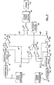
- the system comprises a transducer 5 which produces an electrical signal on a line 6 corresponding to the road speed of the vehicle.
- the transducer 5 may take any suitable form.
- it may be an electromagnetic or photoelectric type of device arranged to receive electromagnetic or photoelectric pulses in dependence on the road speed of the vehicle, such as by being electromagnetically or photoelectrically responsive to the rotational speed of the propellor shaft of the vehicle.
- the resultant pulsed output is used to drive a monostable 7 which produces a train of pulses on a line 8 of similar length but whose pulse repetition frequency depends on the road speed.
- this is preferably smoothed or otherwise processed by a processing circuit 9 so as to produce a generally DC electrical signal Vs1 on a line 10 whose magnitude is proportional to the vehicle road speed.
- Vs1 is passed through an AC amplifier 10 which passes the signal Vs1 and amplifies sudden changes in the DC value.
- the amplifier output is passed into an error amplifier 12 which compares its magnitude with a reference signal Vr1 on a line 14 representing the desired speed of the vehicle.
- the reference on the line 14 may be derived from a manually settable control which is set by the driver, for example a potentiometer.
- a store could be provided which is instantaneously connected to receive the signal on the line 10 when the vehicle is running at a road speed desired by the driver and then stores that magnitude of signal which thereafter provides the reference on the line 14.
- Another possibility is to provide a fixed reference on the line 14, that is, a signal whose level is not under control of the driver but represents the maximum speed which it is desired to permit the vehicle to run.
- the error amplifier 12 compares the magnitudes of the signals received on the lines 10 and 14 and produces an error signal, Ve1, on a line 16 whose magnitude represents the error (if any) between the desired and actual road speeds and whose sign indicates whether the actual road speed is greater or less than the desired speed.
- the error signal is passed to an engine power control unit 18.
- This is arranged to respond to the sign and magnitude of Ve1 and to adjust the power of the engine 20 of the vehicle in such a sense as to bring the actual road speed of the vehicle to the desired value, whereupon, of course, the signal Ve1 tends to zero.
- the control unit 18 may be electromechanical in nature such as in the form of an electro-pneumatic arrangement, or may be an electric motor, which adjusts the carburettor or diesel injection system of the vehicle so as to control the engine power in the desired manner and independently of the driver's foot control. Examples of forms which the engine power control unit 18 may take are shown in U.K. Patents Nos. 1486822 and 1493623.
- the error signal Ve1 is passed to a comparator 22 on a line 24.
- Comparator 22 compares the magnitude of the error signal Ve1 with a fixed reference Vr2 on a line 26.
- Vr2 is selected so that if the magnitude of Ve1 exceeds this reference, this means that the actual road speed of the vehicle is exceeding the desired value by at least a predetermined (relatively small) amount, and in such a case the comparator 22 produces an output signal Ve2 on a line 28.
- Signal Ve2 is passed to a retarder unit 30 which acts positively on the vehicle in a suitable manner so as actually to reduce its speed.
- the retarder unit 30 may be in the form of the actual brakes of the vehicle so that these are applied to bring the road speed of the vehicle down to the desired level. More advantageously, however, the retarder unit 30 takes the form of the electrical retarder which is commonly fitted to coaches and which acts usually on the propellor shaft of the vehicle so as to provide electrical braking of the vehicle.
- a further transducer 40 is provided which produces an electrical signal on a line 42 dependent on the actual engine speed of the vehicle.
- the transducer 40 may take any suitable form and may be actuated, for example, by electrical impulses from the ignition system of the engine if it is of the spark ignition type. If it is a diesel engine, then a separate transducer may be provided.
- the electrical signal 42 if of pulsed form, is passed to a monostable 43 corresponding to the monostable 7 and the resultant pulse train is fed to a processing circuit 44 corresponding to the circuit 9 to produce a DC signal Vs2 on a line 45 whose magnitude corresponds to the actual engine speed.Vs2 is passed to an amplifier 46 corresponding to amplifier 10 and thence to an error amplifier 48 which compares it with a reference signal Vr3 on a line 50 representing a desired limit speed for the engine.
- Vr3 would normally be a fixed reference which would be set by the vehicle manufacturer or vehicle owner (that is, it would not be in control of the driver).
- the error amplifier 48 produces an error signal Ve3 on a line 49 whose sign and magnitude represent the sign and magnitude of any error between the actual engine speed and the limit speed.
- Signal Ve3 is, together with the signal Ve1, passed to a comparator 50.
- Comparator 50 now acts to compare both the signals Ve1 and Ve3 with each other. Whichever is the greater will appear on the output of the comparator and will actuate the engine power control 18 so as to tend to reduce the error to zero.
- the signal Vs1 is fed into a comparator 52 where it is compared with reference Vr1.
- signal Vs3 is fed into another comparator 54 where it is compared with reference Vr3.
- the comparators 52 and 54 therefore produce error signals on lines 56 and 58 which respectively correspond to Ve1 and Ve3 but which are not subject to the effect of the AC amplifiers 7 and 45 and which are only produced if the respective speed error is positive (that is, the actual road or engine speed is greater than the desired level).
- These error signals are fed to an OR gate 60.
- the output of gate 60 is fed to the retarder control 30.
- the system of Figure 2 provides the additional safeguard of positively braking or retarding the vehicle in conditions when the engine speed is excessive even if the road speed is not. Thus, for example, it will positively brake or retard the vehicle if the driver should engage a lower gear at an excessive road speed. It will thus protect the vehicle against action by the driver in selecting a low gear at too higher speed on descending a hill (in an attempt to build up engine speed for a subsequent ascent).
Landscapes
- Engineering & Computer Science (AREA)
- Chemical & Material Sciences (AREA)
- Combustion & Propulsion (AREA)
- Transportation (AREA)
- Mechanical Engineering (AREA)
- Automation & Control Theory (AREA)
- Control Of Vehicle Engines Or Engines For Specific Uses (AREA)
- Control Of Driving Devices And Active Controlling Of Vehicle (AREA)
- Electrical Control Of Air Or Fuel Supplied To Internal-Combustion Engine (AREA)
- Transmission Of Braking Force In Braking Systems (AREA)
- Controls For Constant Speed Travelling (AREA)
Applications Claiming Priority (2)
| Application Number | Priority Date | Filing Date | Title |
|---|---|---|---|
| GB8332536 | 1983-12-06 | ||
| GB08332536A GB2152166A (en) | 1983-12-06 | 1983-12-06 | Automatic vehicle speed control |
Publications (2)
| Publication Number | Publication Date |
|---|---|
| EP0145374A2 true EP0145374A2 (fr) | 1985-06-19 |
| EP0145374A3 EP0145374A3 (fr) | 1986-01-02 |
Family
ID=10552904
Family Applications (1)
| Application Number | Title | Priority Date | Filing Date |
|---|---|---|---|
| EP84308086A Withdrawn EP0145374A3 (fr) | 1983-12-06 | 1984-11-21 | Systèmes automatiques pour commande de vitesse |
Country Status (4)
| Country | Link |
|---|---|
| EP (1) | EP0145374A3 (fr) |
| JP (1) | JPS60143136A (fr) |
| AU (1) | AU3636484A (fr) |
| GB (1) | GB2152166A (fr) |
Cited By (15)
| Publication number | Priority date | Publication date | Assignee | Title |
|---|---|---|---|---|
| EP0241872A1 (fr) * | 1986-04-18 | 1987-10-21 | Csepel Autogyár | Procédé et dispositif de commande d'un ralentisseur hydrodynamique pour véhicules à moteur |
| EP0299235A3 (en) * | 1987-07-16 | 1989-08-09 | Toyota Jidosha Kabushiki Kaisha | Speed control system for a vehicle |
| EP0315207A3 (en) * | 1987-11-06 | 1989-09-13 | Nissan Motor Co., Ltd. | A system and method for automatically controlling a vehicle speed to a desired cruise speed with a release function |
| EP0336913A3 (fr) * | 1988-03-31 | 1991-05-02 | Saab-Scania Aktiebolag | Procédé et dispositif pour maintenir la vitesse constante par activation du système de freinage d'un véhicule à moteur |
| WO1992017354A1 (fr) * | 1991-04-08 | 1992-10-15 | Caterpillar Inc. | Commande de ralentissement automatique d'un vehicule |
| DE4313685A1 (de) * | 1993-04-27 | 1993-09-30 | Voith Turbo Kg | Verfahren zur Regelung auf konstante Fahrgeschwindigkeit und Regelsystem zur Durchführung des Verfahrens |
| DE4341212A1 (de) * | 1993-12-03 | 1994-04-21 | Voith Turbo Kg | Verfahren zur Geschwindigkeitsbegrenzung in allen Fahrzuständen und Vorrichtung zur Durchführung des Verfahrens |
| WO1995013203A1 (fr) * | 1993-11-10 | 1995-05-18 | Robert Bosch Gmbh | Procede et dispositif pour la commande d'un vehicule |
| EP0656290A1 (fr) * | 1993-12-03 | 1995-06-07 | VOITH TURBO GMBH & CO. KG | Dispositif de commande pour influencer la vitesse d'un véhicule |
| AU661966B2 (en) * | 1991-04-08 | 1995-08-17 | Caterpillar Inc. | Automatic vehicle speed retarding control |
| WO1996023679A1 (fr) * | 1995-02-03 | 1996-08-08 | Robert Bosch Gmbh | Systeme de freinage |
| DE19961720A1 (de) * | 1999-12-22 | 2001-08-16 | Daimler Chrysler Ag | Verfahren und Vorrichtung zur Geschwindigkeitsregelung eines Kraftfahrzeugs |
| WO2004048172A1 (fr) * | 2002-11-26 | 2004-06-10 | Volvo Lastvagnar Ab | Procede et dispositif de repartition du couple de freinage sur un vehicule |
| EP2020353A1 (fr) * | 2007-07-30 | 2009-02-04 | Robert Bosch GmbH | Procédé et dispositif de régulation de la vitesse d'un véhicule |
| CN104085304A (zh) * | 2014-06-30 | 2014-10-08 | 潍柴动力股份有限公司 | 基于缓速器的车速限制方法以及车速限制系统 |
Families Citing this family (15)
| Publication number | Priority date | Publication date | Assignee | Title |
|---|---|---|---|---|
| GB9420561D0 (en) * | 1994-10-12 | 1994-11-30 | Rover Group | A wheeled vehicle |
| DE19515059A1 (de) | 1994-11-25 | 1996-05-30 | Teves Gmbh Alfred | Fahrstabilitätsregler mit reibwertabhängiger Begrenzung der Referenzgierrate |
| US5711024A (en) | 1994-11-25 | 1998-01-20 | Itt Automotive Europe Gmbh | System for controlling yaw moment based on an estimated coefficient of friction |
| US5694321A (en) | 1994-11-25 | 1997-12-02 | Itt Automotive Europe Gmbh | System for integrated driving stability control |
| US5732377A (en) | 1994-11-25 | 1998-03-24 | Itt Automotive Europe Gmbh | Process for controlling driving stability with a yaw rate sensor equipped with two lateral acceleration meters |
| US5742507A (en) | 1994-11-25 | 1998-04-21 | Itt Automotive Europe Gmbh | Driving stability control circuit with speed-dependent change of the vehicle model |
| US5710705A (en) | 1994-11-25 | 1998-01-20 | Itt Automotive Europe Gmbh | Method for determining an additional yawing moment based on side slip angle velocity |
| US5732379A (en) | 1994-11-25 | 1998-03-24 | Itt Automotive Europe Gmbh | Brake system for a motor vehicle with yaw moment control |
| US5701248A (en) | 1994-11-25 | 1997-12-23 | Itt Automotive Europe Gmbh | Process for controlling the driving stability with the king pin inclination difference as the controlled variable |
| US5732378A (en) | 1994-11-25 | 1998-03-24 | Itt Automotive Europe Gmbh | Method for determining a wheel brake pressure |
| US5710704A (en) | 1994-11-25 | 1998-01-20 | Itt Automotive Europe Gmbh | System for driving stability control during travel through a curve |
| US5774821A (en) | 1994-11-25 | 1998-06-30 | Itt Automotive Europe Gmbh | System for driving stability control |
| CN1173216A (zh) * | 1994-12-27 | 1998-02-11 | 株式会社小松制作所 | 作业车辆的车速限制装置及其方法 |
| JPH07324753A (ja) * | 1995-03-09 | 1995-12-12 | Matsushita Electric Ind Co Ltd | ガスコンロ |
| SE520888C2 (sv) | 1999-07-06 | 2003-09-09 | Scania Cv Ab | Dieselmotor, samt ett sätt att styra denna |
Family Cites Families (17)
| Publication number | Priority date | Publication date | Assignee | Title |
|---|---|---|---|---|
| US3181677A (en) * | 1960-11-03 | 1965-05-04 | Gen Motors Corp | Transmission |
| US3524982A (en) * | 1967-12-29 | 1970-08-18 | Pullman Inc | Vehicle speed control device |
| GB1210710A (en) * | 1968-05-03 | 1970-10-28 | Robert Eugene Cleary | Flow measuring device |
| US3882973A (en) * | 1972-07-19 | 1975-05-13 | Caterpillar Tractor Co | Automatic retarder control system |
| GB1462209A (en) * | 1973-10-17 | 1977-01-19 | Krampe & Co | Safety braking system for railways |
| GB1493623A (en) * | 1974-03-05 | 1977-11-30 | Ass Eng Ltd | Speed control systems |
| DE2444518A1 (de) * | 1974-09-18 | 1976-04-01 | Peugeot | System zur geschwindigkeitsbegrenzung eines fahrzeuges |
| GB1486822A (en) * | 1975-01-13 | 1977-09-28 | Ass Eng Ltd | Actuator devices |
| US3999386A (en) * | 1975-09-11 | 1976-12-28 | Sundstrand Corporation | Overspeed protection control for an engine |
| DE2819175A1 (de) * | 1978-05-02 | 1979-11-15 | Wabco Fahrzeugbremsen Gmbh | Einrichtung zur regelung der geschwindigkeit eines fahrzeugs |
| GB1602487A (en) * | 1978-05-31 | 1981-11-11 | Ass Eng Ltd | Vehicle speed control systems |
| GB2056125B (en) * | 1979-08-03 | 1983-07-06 | Ass Eng Ltd | Vehicle speed control system |
| SE437790B (sv) * | 1979-09-04 | 1985-03-18 | Hans Jonasson | Styrverkan for samverkan med en for en dieselmotor avsedd bromsutrustning |
| ES8205160A1 (es) * | 1980-03-19 | 1982-06-16 | Ogden Electronics Ltd | Perfeccionamientos en los aparatos para controlar la veloci-dad del motor de un vehiculo |
| GB2082700B (en) * | 1980-08-06 | 1984-05-10 | Wheway Watson Holdings | Method of arresting a vehicle vehicle having arrestor means |
| GB2081934B (en) * | 1980-08-08 | 1984-03-07 | Ass Eng Ltd | Automatic speed control systems |
| GB2081933B (en) * | 1980-08-08 | 1984-11-14 | Ass Eng Ltd | Automatic speed control systems |
-
1983
- 1983-12-06 GB GB08332536A patent/GB2152166A/en not_active Withdrawn
-
1984
- 1984-11-21 EP EP84308086A patent/EP0145374A3/fr not_active Withdrawn
- 1984-12-06 AU AU36364/84A patent/AU3636484A/en not_active Abandoned
- 1984-12-06 JP JP59256625A patent/JPS60143136A/ja active Pending
Cited By (23)
| Publication number | Priority date | Publication date | Assignee | Title |
|---|---|---|---|---|
| EP0241872A1 (fr) * | 1986-04-18 | 1987-10-21 | Csepel Autogyár | Procédé et dispositif de commande d'un ralentisseur hydrodynamique pour véhicules à moteur |
| EP0299235A3 (en) * | 1987-07-16 | 1989-08-09 | Toyota Jidosha Kabushiki Kaisha | Speed control system for a vehicle |
| EP0315207A3 (en) * | 1987-11-06 | 1989-09-13 | Nissan Motor Co., Ltd. | A system and method for automatically controlling a vehicle speed to a desired cruise speed with a release function |
| US5127487A (en) * | 1987-11-06 | 1992-07-07 | Nissan Motor Company, Limited | System and method for automatically controlling a vehicle speed to a desired cruise speed with a release function |
| EP0336913A3 (fr) * | 1988-03-31 | 1991-05-02 | Saab-Scania Aktiebolag | Procédé et dispositif pour maintenir la vitesse constante par activation du système de freinage d'un véhicule à moteur |
| WO1992017354A1 (fr) * | 1991-04-08 | 1992-10-15 | Caterpillar Inc. | Commande de ralentissement automatique d'un vehicule |
| US5983149A (en) * | 1991-04-08 | 1999-11-09 | Caterpillar Inc. | Automatic vehicle speed retarding control through actuation of wheel brakes |
| AU661966B2 (en) * | 1991-04-08 | 1995-08-17 | Caterpillar Inc. | Automatic vehicle speed retarding control |
| DE4313685A1 (de) * | 1993-04-27 | 1993-09-30 | Voith Turbo Kg | Verfahren zur Regelung auf konstante Fahrgeschwindigkeit und Regelsystem zur Durchführung des Verfahrens |
| KR100351394B1 (ko) * | 1993-11-10 | 2002-11-09 | 로베르트 보쉬 게엠베하 | 차량의속도제어방법및장치 |
| WO1995013203A1 (fr) * | 1993-11-10 | 1995-05-18 | Robert Bosch Gmbh | Procede et dispositif pour la commande d'un vehicule |
| DE4338399B4 (de) * | 1993-11-10 | 2013-02-21 | Robert Bosch Gmbh | Verfahren und Vorrichtung zur Steuerung eines Fahrzeugs |
| US5794735A (en) * | 1993-11-10 | 1998-08-18 | Robert Bosch Gmbh | Vehicle deceleration by engine control followed by brake control |
| EP0656290A1 (fr) * | 1993-12-03 | 1995-06-07 | VOITH TURBO GMBH & CO. KG | Dispositif de commande pour influencer la vitesse d'un véhicule |
| EP0656276A1 (fr) * | 1993-12-03 | 1995-06-07 | VOITH TURBO GMBH & CO. KG | Méthode de limitation de vitesse pour tous les modes de conduite et dispositif pour la mise en oeuvre de cette méthode |
| DE4341212A1 (de) * | 1993-12-03 | 1994-04-21 | Voith Turbo Kg | Verfahren zur Geschwindigkeitsbegrenzung in allen Fahrzuständen und Vorrichtung zur Durchführung des Verfahrens |
| WO1996023679A1 (fr) * | 1995-02-03 | 1996-08-08 | Robert Bosch Gmbh | Systeme de freinage |
| DE19961720A1 (de) * | 1999-12-22 | 2001-08-16 | Daimler Chrysler Ag | Verfahren und Vorrichtung zur Geschwindigkeitsregelung eines Kraftfahrzeugs |
| DE19961720C2 (de) * | 1999-12-22 | 2001-11-29 | Daimler Chrysler Ag | Verfahren und Vorrichtung zur Geschwindigkeitsregelung eines Kraftfahrzeugs |
| WO2004048172A1 (fr) * | 2002-11-26 | 2004-06-10 | Volvo Lastvagnar Ab | Procede et dispositif de repartition du couple de freinage sur un vehicule |
| EP2020353A1 (fr) * | 2007-07-30 | 2009-02-04 | Robert Bosch GmbH | Procédé et dispositif de régulation de la vitesse d'un véhicule |
| US8160798B2 (en) | 2007-07-30 | 2012-04-17 | Robert Bosch Gmbh | Method and device for regulating the velocity of a vehicle |
| CN104085304A (zh) * | 2014-06-30 | 2014-10-08 | 潍柴动力股份有限公司 | 基于缓速器的车速限制方法以及车速限制系统 |
Also Published As
| Publication number | Publication date |
|---|---|
| AU3636484A (en) | 1985-06-13 |
| JPS60143136A (ja) | 1985-07-29 |
| EP0145374A3 (fr) | 1986-01-02 |
| GB8332536D0 (en) | 1984-01-11 |
| GB2152166A (en) | 1985-07-31 |
Similar Documents
| Publication | Publication Date | Title |
|---|---|---|
| GB2152166A (en) | Automatic vehicle speed control | |
| US4779202A (en) | Propulsion control using longitudinal acceleration and steering angle to determine slip threshold | |
| US4763262A (en) | Propulsion control using longitudinal acceleration, steering angle, and speed to select slip threshold | |
| US4765430A (en) | Method and arrangement for propulsion regulation of an automobile | |
| US4763263A (en) | Propulsion control using longitudinal acceleration to determine slip thresholds | |
| US5213177A (en) | Traction control system responsive to wheel speed fluctuations | |
| JP2929490B2 (ja) | 駆動スリツプ制御装置 | |
| HU218526B (hu) | Eljárás és berendezés járművek vezérlésére | |
| EP0078655A2 (fr) | Système de commande de dérapage de roue | |
| US4962970A (en) | Anti-lock braking system | |
| SE461717B (sv) | Foerfarande och anordning foer bestaeming av slirningstroeskelvaerden vid ett drivslirningsreglersystem foer ett motorfordon | |
| US4354467A (en) | Vehicle speed control systems | |
| GB2204368A (en) | Wheel-slip control | |
| EP0823348B1 (fr) | Système et méthode pour commander la traction d'un véhicule électrique | |
| US6185495B1 (en) | System for producing a braking signal in a motor vehicle | |
| US6182002B1 (en) | Vehicle acceleration based traction control | |
| US5117933A (en) | Drive slip regulating system for a four-wheel drive vehicle | |
| KR100374430B1 (ko) | 트랙션슬립제어기 | |
| JP2502633B2 (ja) | 車両用駆動力制御装置 | |
| US5562569A (en) | Method of gear detection for controlling drive torque | |
| US6349255B1 (en) | Method and device for producing a signal representing a motor vehicle running conditions | |
| JPH09189257A (ja) | 自動車における負荷変化反応の緩和方法および装置 | |
| US5884719A (en) | Method and apparatus for drive slip control | |
| AU2828801A (en) | Method and device for adjusting the braking and/or drive effects on wheels of motor vehicles | |
| US6535809B1 (en) | Vehicle engine torque control with engine drag control mode |
Legal Events
| Date | Code | Title | Description |
|---|---|---|---|
| PUAI | Public reference made under article 153(3) epc to a published international application that has entered the european phase |
Free format text: ORIGINAL CODE: 0009012 |
|
| AK | Designated contracting states |
Designated state(s): DE FR IT SE |
|
| PUAL | Search report despatched |
Free format text: ORIGINAL CODE: 0009013 |
|
| AK | Designated contracting states |
Designated state(s): DE FR IT SE |
|
| 17P | Request for examination filed |
Effective date: 19851112 |
|
| STAA | Information on the status of an ep patent application or granted ep patent |
Free format text: STATUS: THE APPLICATION HAS BEEN WITHDRAWN |
|
| 18W | Application withdrawn |
Withdrawal date: 19860116 |
|
| RIN1 | Information on inventor provided before grant (corrected) |
Inventor name: CALDWELL, KENNETH BRUCE |