EP0145382A2 - Générateur de mouvement hélicoidal axial - Google Patents
Générateur de mouvement hélicoidal axial Download PDFInfo
- Publication number
- EP0145382A2 EP0145382A2 EP84308114A EP84308114A EP0145382A2 EP 0145382 A2 EP0145382 A2 EP 0145382A2 EP 84308114 A EP84308114 A EP 84308114A EP 84308114 A EP84308114 A EP 84308114A EP 0145382 A2 EP0145382 A2 EP 0145382A2
- Authority
- EP
- European Patent Office
- Prior art keywords
- vanes
- flow path
- gas flow
- annular gas
- duct
- Prior art date
- Legal status (The legal status is an assumption and is not a legal conclusion. Google has not performed a legal analysis and makes no representation as to the accuracy of the status listed.)
- Ceased
Links
Images

Classifications
-
- F—MECHANICAL ENGINEERING; LIGHTING; HEATING; WEAPONS; BLASTING
- F23—COMBUSTION APPARATUS; COMBUSTION PROCESSES
- F23D—BURNERS
- F23D1/00—Burners for combustion of pulverulent fuel
- F23D1/02—Vortex burners, e.g. for cyclone-type combustion apparatus
-
- F—MECHANICAL ENGINEERING; LIGHTING; HEATING; WEAPONS; BLASTING
- F23—COMBUSTION APPARATUS; COMBUSTION PROCESSES
- F23C—METHODS OR APPARATUS FOR COMBUSTION USING FLUID FUEL OR SOLID FUEL SUSPENDED IN A CARRIER GAS OR AIR
- F23C7/00—Combustion apparatus characterised by arrangements for air supply
- F23C7/002—Combustion apparatus characterised by arrangements for air supply the air being submitted to a rotary or spinning motion
- F23C7/004—Combustion apparatus characterised by arrangements for air supply the air being submitted to a rotary or spinning motion using vanes
- F23C7/006—Combustion apparatus characterised by arrangements for air supply the air being submitted to a rotary or spinning motion using vanes adjustable
Definitions
- an annular gas flow path having a portion of which the outer boundary has a cross-section that tapers in the general direction of flow along the path and of which the inner boundary is cylindrical, there being a ring of swirl inducing vanes lying within the portion and reciprocable as a unit in the general direction of flow between a position in which gas can pass the vanes only by flowing between the vanes and a position in which some of the air can flow between the vanes and some of the air can flow past, outside, the vanes.
- Figure 1 illustrates a burner mounted at an opening 1 in furnace wall 2. Coaxial with the opening 1 is duct 3 through which pulverised fuel entrained in primary air can be discharged into the furnace. Concentric with the duct 3 is a core tube 4 that houses a light-up burner (not shown).
- a duct 8 Sealed at its leading end around the opening 1 is a duct 8 for secondary air. Secondary air passes to the duct 8 from the wind box 9 through six plane, equispaced and radially extending blades 10 that extend between a rear wall 11 and a flange 12. The flange 12 extends radially outwardly from the wider end of a conically tapering portion 16 that is connected at its narrower end to the duct 8.
- the forward end of the duct 2, tube 4 and duct 8 lie at the level of the outer surface of the wall 2.
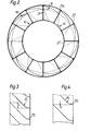
- a unit 20 comprising a set of similar and equispaced vanes 21, is disposed within the tapering portion 16.
- the unit comprises an inner ring 22 of constant cross-section that can reciprocate along the duct 3 and an outer ring 23 so shaped that at the most forward position to which the unit can move ( in which position it is shown in Figure 1), the outer ring 23 mates with the tapering position 16.
- Both rings 22 and 23 extend from end to end of the vanes; ring 22 extends a little rearwardly of them.
- the vanes 21 are each connected at their edges to both rings 22 and 23.
- the wider end 21a of each vane extends radially; downstream of that end the vanes curve to induce swirl in the air passing between them.
- the edges of the vanes 21 are inclined to the radius at an angle in the order of 45°.
- every fourth vane 21 Connected to the rear end of every fourth vane 21 is a rod 30 that extends rearwardly from the vane 30, parallel to the axis, and through the rear wall 11.
- the end of each rod 30 that projects beyond the rear wall 11 is threaded and carries a screw member 31.
- the unit 20 can be moved back from the position in which it is shown in Figure 1 to position indicated in broken lines in Figure 1.
- all the secondary air must pass between the vanes 21 and so be caused to swirl. It will also be accelerated.
- the unit has been retracted, only some of the secondary air passes between the vanes; the rest passes as an envelope past the outer edges of the vanes.
- reciprocal movement of the unit 20 could be effected by means remote from the burner.
- a conical baffle should be located around the tube 4 at its junction with the rear wall 11 to steer the air from its radially inward flow past the blades 10 to its axial flow between the vanes 21. The effect of the baffle will be to inhibit turbulance and the losses resulting from it.
Landscapes
- Engineering & Computer Science (AREA)
- Chemical & Material Sciences (AREA)
- Combustion & Propulsion (AREA)
- Mechanical Engineering (AREA)
- General Engineering & Computer Science (AREA)
Applications Claiming Priority (2)
| Application Number | Priority Date | Filing Date | Title |
|---|---|---|---|
| GB8331128 | 1983-11-22 | ||
| GB838331128A GB8331128D0 (en) | 1983-11-22 | 1983-11-22 | Axial swirl generators |
Publications (2)
| Publication Number | Publication Date |
|---|---|
| EP0145382A2 true EP0145382A2 (fr) | 1985-06-19 |
| EP0145382A3 EP0145382A3 (fr) | 1985-10-02 |
Family
ID=10552155
Family Applications (1)
| Application Number | Title | Priority Date | Filing Date |
|---|---|---|---|
| EP84308114A Ceased EP0145382A3 (fr) | 1983-11-22 | 1984-11-22 | Générateur de mouvement hélicoidal axial |
Country Status (5)
| Country | Link |
|---|---|
| EP (1) | EP0145382A3 (fr) |
| DK (1) | DK552484A (fr) |
| FI (1) | FI844588L (fr) |
| GB (1) | GB8331128D0 (fr) |
| ZA (1) | ZA849100B (fr) |
Cited By (3)
| Publication number | Priority date | Publication date | Assignee | Title |
|---|---|---|---|---|
| EP0945678A3 (fr) * | 1998-03-25 | 2000-01-19 | ENEL S.p.A. | Brûleur à faible taux de NOx pour combustibles liquides et gazeux |
| US6322610B1 (en) | 1998-11-10 | 2001-11-27 | Danieli & C. Officine Meccaniche Spa | Integrated device to inject oxygen, technological gases and solid material in powder form and method to use the integrated device for the metallurgical processing of baths of molten metal |
| FR2887597A1 (fr) * | 2005-06-27 | 2006-12-29 | Egci Pillard Sa | Conduite annulaire et bruleur comportant une telle conduite |
Family Cites Families (2)
| Publication number | Priority date | Publication date | Assignee | Title |
|---|---|---|---|---|
| GB672583A (en) * | 1950-09-30 | 1952-05-21 | Wallsend Slipway & Engineering | Improvements in air directors for use with liquid fuel and/or powdered fuel burners |
| DE2908448C2 (de) * | 1979-03-05 | 1983-04-14 | L. & C. Steinmüller GmbH, 5270 Gummersbach | Brenner zur Verbrennung von stickstoffhaltigen Brennstoffen |
-
1983
- 1983-11-22 GB GB838331128A patent/GB8331128D0/en active Pending
-
1984
- 1984-11-21 DK DK552484A patent/DK552484A/da not_active Application Discontinuation
- 1984-11-22 EP EP84308114A patent/EP0145382A3/fr not_active Ceased
- 1984-11-22 ZA ZA849100A patent/ZA849100B/xx unknown
- 1984-11-22 FI FI844588A patent/FI844588L/fi not_active Application Discontinuation
Cited By (5)
| Publication number | Priority date | Publication date | Assignee | Title |
|---|---|---|---|---|
| EP0945678A3 (fr) * | 1998-03-25 | 2000-01-19 | ENEL S.p.A. | Brûleur à faible taux de NOx pour combustibles liquides et gazeux |
| US6322610B1 (en) | 1998-11-10 | 2001-11-27 | Danieli & C. Officine Meccaniche Spa | Integrated device to inject oxygen, technological gases and solid material in powder form and method to use the integrated device for the metallurgical processing of baths of molten metal |
| FR2887597A1 (fr) * | 2005-06-27 | 2006-12-29 | Egci Pillard Sa | Conduite annulaire et bruleur comportant une telle conduite |
| WO2007000512A1 (fr) * | 2005-06-27 | 2007-01-04 | Egci Pillard | Bruleur |
| US9011141B2 (en) | 2005-06-27 | 2015-04-21 | Egci Pillard | Burner |
Also Published As
| Publication number | Publication date |
|---|---|
| FI844588A7 (fi) | 1985-05-23 |
| DK552484A (da) | 1985-05-23 |
| EP0145382A3 (fr) | 1985-10-02 |
| DK552484D0 (da) | 1984-11-21 |
| FI844588L (fi) | 1985-05-23 |
| GB8331128D0 (en) | 1983-12-29 |
| FI844588A0 (fi) | 1984-11-22 |
| ZA849100B (en) | 1985-11-27 |
Similar Documents
| Publication | Publication Date | Title |
|---|---|---|
| FI106405B (fi) | Poltin jauhemaista polttoainetta varten | |
| EP0343767B1 (fr) | Brûleur à combustible pulvérisé | |
| US4147116A (en) | Pulverized coal burner for furnace and operating method | |
| US4457241A (en) | Method of burning pulverized coal | |
| US2335188A (en) | Fuel burner | |
| FI104125B (fi) | Poltin pölymäisen polttoaineen polttamista varten | |
| EP0091988B1 (fr) | Brûleur industriel et procédé pour amener d'air secondaire à un brûleur industriel | |
| US2380463A (en) | Fluent fuel burner | |
| US3922137A (en) | Apparatus for admixing fuel and combustion air | |
| US5392720A (en) | Flame retaining nozzle tip | |
| GB1398007A (en) | Particle separator | |
| GB2121320A (en) | An atomiser appliance for coating objects with powder | |
| EP0145382A2 (fr) | Générateur de mouvement hélicoidal axial | |
| KR960034852A (ko) | 분말연료 버너 | |
| SU1144627A3 (ru) | Топочное устройство дл энергетического котла с р дом растопочных форсунок и способ его работы | |
| US2921542A (en) | Fluid fuel burner | |
| US2485244A (en) | Atomizing device for oil burners | |
| US1994461A (en) | Fuel burner | |
| GB2098721A (en) | A method of igniting a pulverised fuel main burner and a burner arrangement for carrying out the method | |
| GB1168989A (en) | Centrifugal-Type Particle-Fluid-Separators | |
| US1959521A (en) | Air director for liquid fuel or powdered fuel furnaces | |
| US4621582A (en) | Coal burner | |
| US4807435A (en) | Air-breathing jet engine | |
| US3301305A (en) | Combustion apparatus for a boiler | |
| GB658619A (en) | Improvements in or relating to fuel oil burners |
Legal Events
| Date | Code | Title | Description |
|---|---|---|---|
| PUAI | Public reference made under article 153(3) epc to a published international application that has entered the european phase |
Free format text: ORIGINAL CODE: 0009012 |
|
| AK | Designated contracting states |
Designated state(s): DE GB IT NL SE |
|
| PUAL | Search report despatched |
Free format text: ORIGINAL CODE: 0009013 |
|
| AK | Designated contracting states |
Designated state(s): DE GB IT NL SE |
|
| 17P | Request for examination filed |
Effective date: 19860318 |
|
| 17Q | First examination report despatched |
Effective date: 19861203 |
|
| STAA | Information on the status of an ep patent application or granted ep patent |
Free format text: STATUS: THE APPLICATION HAS BEEN REFUSED |
|
| 18R | Application refused |
Effective date: 19890129 |
|
| RIN1 | Information on inventor provided before grant (corrected) |
Inventor name: FULLER, BRIAN WILFRED |