EP0145404B1 - Aufhängung für einen Frankiermaschinendruckkopf - Google Patents
Aufhängung für einen Frankiermaschinendruckkopf Download PDFInfo
- Publication number
- EP0145404B1 EP0145404B1 EP19840308222 EP84308222A EP0145404B1 EP 0145404 B1 EP0145404 B1 EP 0145404B1 EP 19840308222 EP19840308222 EP 19840308222 EP 84308222 A EP84308222 A EP 84308222A EP 0145404 B1 EP0145404 B1 EP 0145404B1
- Authority
- EP
- European Patent Office
- Prior art keywords
- yoke
- printing head
- franking machine
- arms
- printing
- Prior art date
- Legal status (The legal status is an assumption and is not a legal conclusion. Google has not performed a legal analysis and makes no representation as to the accuracy of the status listed.)
- Expired
Links
- 239000000725 suspension Substances 0.000 title description 3
- 238000000429 assembly Methods 0.000 claims description 4
- 239000000463 material Substances 0.000 claims description 4
- 230000001737 promoting effect Effects 0.000 claims 1
- 230000007246 mechanism Effects 0.000 description 14
- 239000004020 conductor Substances 0.000 description 6
- 239000000976 ink Substances 0.000 description 4
- 230000000712 assembly Effects 0.000 description 3
- 229920001971 elastomer Polymers 0.000 description 2
- 230000003993 interaction Effects 0.000 description 2
- 238000005096 rolling process Methods 0.000 description 2
- 241000251468 Actinopterygii Species 0.000 description 1
- 238000004140 cleaning Methods 0.000 description 1
- 238000010276 construction Methods 0.000 description 1
- 238000010348 incorporation Methods 0.000 description 1
- 239000003550 marker Substances 0.000 description 1
- 239000011148 porous material Substances 0.000 description 1
- 230000001681 protective effect Effects 0.000 description 1
- 229920006395 saturated elastomer Polymers 0.000 description 1
Images


Classifications
-
- G—PHYSICS
- G07—CHECKING-DEVICES
- G07B—TICKET-ISSUING APPARATUS; FARE-REGISTERING APPARATUS; FRANKING APPARATUS
- G07B17/00—Franking apparatus
- G07B17/00459—Details relating to mailpieces in a franking system
- G07B17/00508—Printing or attaching on mailpieces
-
- G—PHYSICS
- G07—CHECKING-DEVICES
- G07B—TICKET-ISSUING APPARATUS; FARE-REGISTERING APPARATUS; FRANKING APPARATUS
- G07B17/00—Franking apparatus
- G07B17/00459—Details relating to mailpieces in a franking system
- G07B17/00508—Printing or attaching on mailpieces
- G07B2017/00516—Details of printing apparatus
- G07B2017/00524—Printheads
- G07B2017/00548—Mechanical printhead
Definitions
- This invention concerns franking machines and, in particular an improved suspension system for printing heads fitted therein.
- Relative movement must be provided for between a printing head containing inked characters for forming an impression on an envelope or packet and a platen in which the envelope or packet is rested during franking.
- a franking machine containing a printing head which itself includes at least one printface on the underside thereof, which when inked, will form an impression on the surface of an envelope or packet placed on a platen underneath the printing head, wherein the printing head is attached to an - elongated support means which is connected to the remainder of the franking machine through a joint which permits at least limited movement of the support means in the relation to the remainder of the machine in a plane cutting transversely through the joint and the printing head, which movement urges the end of the support means carrying the printing head in a generally downward direction towards the platen during the printing operation.
- a franking machine is referred to below as a franking machine of the type defined.
- US-A-4410287 discloses a billet marker in which a marking wheel is pivotally supported on a pair of parallel arms to enable the marking wheel to move through an arcuate path . towards a billet to be marked.
- the present invention seeks to provide an improved suspension system for such printing heads of franking machines.
- a franking machine of the type defined characterised in that the support means is in the form of two elongated arms connected at one of their ends by a yoke; in that the printing head is pivotally attached to said arms between their free ends with the axis of pivoting lying in, or being parallel and closely spaced from, the plane containing the print face so as to reduce sliding movement of the print face relative to an envelope or packet during downward movement of the printing head, the printing head being resiliently held in its position relative to the arms by spring means; and in that the joint is arranged such that, on exerting a thrust on the yoke to operate the printing head, at least a limited tilting movement of the arms out of their normal plane is permitted, thereby allowing a limited tilting movement of the printing head from side to side.
- the arms including the yoke are normally held in an elevated position relative to the platen under the action of a spring or other resilient device and are urged thereby against retaining member determining the said elevated position.
- Figures 1 and 2 there is shown a basic printing head mechanism of the type which can be incorporated into a franking machine or the like.
- the mechanism shown in Figures 1 and 2 and the subsequent five Figures is intended to illustrate the principle of operation and construction more clearly than is the case when the components are miniaturised and compacted more densely than in the mechanism shown.
- a final form of the apparatus illustrating the use of the same type of printing head in a parallel multi-head arrangement in a franking machine is shown in later Figures.
- a baseplate 10 serves as a support for two sideplates 12 and 14.
- a drive motor and gearbox assembly (not shown in detail) 16 is attached to and extends beyond the side wall 14 and serves to rotate a drive shaft 18 carrying a main print head operating cam 20 and a supplementary switch-actuating cam 22.
- a rod 24 which is parallel to but spaced from and to the rear of the drive shaft 18.
- the printing head comprises a generally rectangular housing 26 which is pivotally attached at a stub shaft 28 on the one side and at a similar point (not visible in the drawings) on the other side of the housing 26 by means of stub-axles, to opposite arms 30 and 32 connected by a yoke 34.
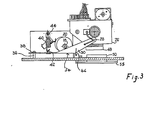
- the yoke 34 is relatively freely floating in that it is secured to the baseplate 10 through a lost motion connection best seen in Figures 3 and 4.
- This comprises an upstanding pin 36 having an enlarged head 38 which holds captive the generally flat plate section of the yoke 34.
- the latter includes an aperture (not shown) which is oversize relative to the diameter of the pin 36 so that the plate of the yoke 34 can, in fact, tilt to one side or the other as well as in a generally up and down manner relative to the baseplate 10.
- the yoke 34 is held in place by means of a spring 40 located between a point of attachment at 42 in the middle of the plate of the yoke assembly 34 and attached to a fish plate 44 which itself is threaded on the rod 24 extending between the two sidecheeks 12 and 14.
- the spring is selected so as to still be in tension when the arms 30 and 32 engage the underside of the drive shaft 18 which is the normal centralised position for the assembly under the action of the spring 40.
- the yoke assembly and therefore the printing head 26 can be moved in a downward direction for printing by rotation of the cam 20 to deflect the yoke 34 in the direction of the arrow 46 (see Figure 3).
- the printing head includes a print face 48 containing characters which, if inked, will leave a suitable impression on an envelope or letter situated thereunder and aligned with and below the print face 48 is a platen 50 which is located in position by means of an underplate assembly 55 secured in position by means of four screws as can best be seen in Figure 7.
- Removal of the plate 50 gives uninterrupted access through an aperture (not shown) in the baseplate 10, to the print face 48 to facilitate checking, cleaning and replacing members of the print head assembly.
- the orientation of the print head relative to the arms 30 and 32 is maintained by means of at least one spring best seen in Figure 1.
- the spring includes two radial arms 52 and 54 and is looped at its centre around the protruding end of the stub-shaft 28 the outboard end of which is enlarged to prevent the spring loop from leaving the stub-shaft.
- the outboard ends of the radial arms 52 and 54 are secured on the one hand in an aperture 56 in the arm 30 and around a fixed stand-off 58 attached to the side of the print head housing 26.
- a similar spring (not shown) is provided on the other side of the housing 26 between it and the other arm 32.
- the springs are selected so as to hold the print head housing 26 in the orientation shown in Figures 1, 2 and 3. Any attempt to tilt the print head housing 26 in either direction denoted by the double-headed arrow 60 in Figure 1 will be resisted by the spring and the restoring force stored in the spring will tend to return the housing 26 to the orientation shown in Figures 1 to 3 as soon as any force tending to tilt the housing 26 relative to the yoke assembly is removed.
- Such a tilting force is, of course, exerted on the printing head housing 26 in the event that an envelope or package is located below the print face 48 which is not of uniform thickness so that part of the print face is prevented from -travelling in a downward direction by the same amount as another part of the print4ace.
- the print head housing 26 can, relative to the baseplate 10 and therefore the platen 50, tilt not only in the direction of the double-headed arrow 60 (Fig. 1) but also from side to side as indicated by the curved arrows 62 and 64 in Figure 1.
- the printing head can therefore accommodate gross unevenness in a packet or envelope located therebelow.
- the printing head itself includes four endless belts of which one is shown at 66 in Figure 5, arranged in parallel-spaced arrangement within the head. Each follows a generally oval path and at its lower end passes around an inking reservoir and transfer pad not shown in detail but designated by reference numeral 68. To this end the material from which the endless loop 66 is formed is preferably porous at least to certain printing inks and forms a so-called retentive pad porous rubber printing medium.
- the belt or loop 66 is formed around its external surface with a series of upstanding segments such as 70 and 72 each of which can if desired carry a character in relief which when the material forming the belt or loop 66 is saturated with ink will form an impression of the character on a sheet of paper or the like located below the printing head in the position designated in dotted outline at 74.
- an opening is provided in the underside of the housing through which the lowermost of the segments 70, 72 etc. can just protrude and in the illustration this is denoted by reference numeral. 76.
- the belt passes around a driving pulley 78 which is either mounted directly onto one of the two head driveshafts 80 or 82 or is connected thereto through the intermediary of a uni-directional clutch (to be described).
- the driving wheel 78 can be thought of as comprising the shaft 80 or mounted thereon.
- a first electric motor 84 (see Fig. 2) the output shaft of which includes a toothed pinion 86 which meshes with a gear wheel 88 which in turn drives a second toothed pinion 90 for driving a larger diameter gearwheel 92 splined or otherwise secured to the shaft 82.
- the second motor and gear train for driving the other aligned but separate shaft 80 are not shown in Figures 1 and 2.
- the second motor is mounted back-to-back and may be in axial alignment with a first motor and a second gear train similar to that transmitting drive between the first motor and the shaft 82 is provided between the second motor (not shown) output shaft and the shaft 80.
- Each of the two shafts 80 and 82 extends into the housing 26 by a sufficient amount to almost touch the opposite end of the other shaft. However, the two shafts are entirely separate from a rotational point of view.
- two of the four endless belts such as 70 are driven by one of the shafts 80 and another two are driven by the shaft 82.
- one of the endless belts in each pair is driven through a uni-directional clutch so that rotation of the shaft, for example, 80, in one direction will rotate both of the endless belts associated therewith but in the other direction will only drive the endless belt which is directly connected to the shaft or to a driving wheel itself non-rotatably secured on the shaft. Consequently, the two endless belts can be independently set so as to present selected characters such as 76 for printing by first of all rotating both of the endless belts in one direction until the first character associated with the clutched belt is in position and thereafter rotating the shaft in the opposite sense until the other character associated with the fixed wheel or belt has been moved into position.
- the other pair of endless belts can be set in a similar manner by rotation of the other motor, first in one direction and then the other.
- a separate uni-directional clutch may be provided for each drive to each of the belts so that both belts are completely independent and rotation of the shaft such as 80 in one direction will only cause one of the belts to be rotated whilst rotation in the other direction will cause the other belt to be rotated.
- toothed indexing wheel is associated with each individual belt.
- One such wheel is shown at 94 in Figure 5.
- the spacing between the teeth around the indexing wheel 94 is commensurate with the spacing between the upstanding segments such as 70, 72 around the endless belt 66 so that as the belt rotates so the indexing wheel must rotate by a corresponding number of segments.
- the indexing wheel 94 includes one or more electrical contacts (not shown) which, as the wheel 94 is indexed, make different combinations of connection between a plurality of conductors designated by reference numerals 96 and 98 by way of example only, carried by a conductor card 100 sandwiched between the index wheel 94 and the next index wheel along.
- reference numerals 96 and 98 by way of example only, carried by a conductor card 100 sandwiched between the index wheel 94 and the next index wheel along.
- an electrical signal can be derived indicative of the angular position of each of the four wheels 94 which therefore correspond to the rotational position of the associated four endless belts 66 and therefore the four characters or groups of characters contained by the belts in the window in the underside of the printing head 26.
- the window and surrounding framework constitutes a print face 48 of Figure 3.
- a microswitch 104 is shown mounted close to the second cam 22 mounted on the shaft 18 with the microswitch actuating lever 106 acting as a cam follower.
- the cam is shaped and fitted to the shaft 18 so that the microswitch is operated once every revolution of the shaft 18 and is opened (or closed) as required at a position in which the lobe of the cam 20 is furthest from the plate of the yoke assembly 34.
- print head assembly shown in Figures 1 to 7 is eminently suitable for incorporation into a franking machine in which a plurality of such head assemblies are located side by side. Each different head assembly can then be dedicated to one particular task associated with the franking of mail and appropriate characters and printing devices are located in each such dedicated printing head assembly.
- FIG 8 Arrangements such as this is shown in figure 8 where four such printing heads are mounted at the end of four freely floating yoke or arm assemblies.
- the four printing heads are designated 108, 110, 112 and 114 and their respective support assemblies by the reference numerals 116, 118, 120 and 122.
- Actuating cams each corresponding to the cam 20 of Figure 1, are denoted by reference numerals 124, 126, 128 and 130 respectively.
- the lost motion free pivot points corresponding to the rear pin 36, 38 of Figure 3 are denoted by reference numerals 132, 134, 136 and 138 respectively.
- Springs corresponding to the spring 40 of Figure 3 are shown at 140, 142, 144 and 146.
- cams 124 to 130 are all mounted on a common shaft 148 and drive therefor is derived therefrom a motor and gearbox assembly (not shown) similar to the item 16 of Figure 1.
- Figure 9 illustrates the assembly of Figure 8 from the front as an elevation thereof in the direction of arrow 8.
- Print head 114 and 112 are each an ink-loaded porous rubber stamp having a printface 115 and 113 respectivey containing characters or indicia which when urged into contact with a sheet of paper such as the outside of an envelope or packet will produce a pattern of information thereon.
- the print heads 110 and_ 108 respectively are constructed basically in the same way as the head shown in Figures 1 to 7 in that they comprise a series of endless belts (see Figure 11) of which one is designated 148 which have outwardly protruding segments containing characters for printing, Each of the belts can be indexed by appropriate rotation of one or the other of two drive shafts 150 and 152 which are themselves driven by toothed wheels 154 and 156 respectively themselves driven by worm gears 158 and 160 respectively on the outward shafts of two motors 162 and 164.
- the print head 110 is not motor- driven but is manually rotatable to adjust the print head characters and to this end two thumbwheels 166 and 168 are provided which have external serrations such as at 170 which engage appropriately toothed wheels 172 and 174 respectively.
- the toothed wheels just referred to serve to drive one or other of two short axles (not shown) to rotate one or other of the endless belts such as 176 and the endless belts are engaged by externally segmented indicator wheels of which one is designated at 178 each having external protrusions for engaging in the segments around the endless belt 176 so as to rotate therewith.
- the franking machine thus incorporates three different types of printing head within the overall assembly, two in which the printing plates are self-inked for life and two in which the endless belts are of a porous material and are replenished by ink from a reservoir such as at 184 (see Figure 10).
- Figure 11 shows the layour of the various parts making up the overall assembly at least insofar as the print head 108 is concerned.
- a yoke 116 and spring 140 operating cam 124 on shaft 148 and a stop shaft 186 (not shown in Figure 8) extends across and prevents upward movement of the yoke assembly 116 beyond a certain amount under the action ofthe spring 140.
- the encoder assembly 188 corresponds to the encoder cards 100 of Figures 1 to 7 embodiment and shown diagrammatically at 190 is one of the toothed wheels containing the electrical conductors which set up the contacts and circuits on the encoder boards and which rotates with rotation of the endless belt 148.
- a soft resiliently deformable pad 192 to absorb unevenness and thick contents of envelopes and packets.
- a stop 194 running along the length of the base 195 behind the platen area 192 serves as a guide as to where the envelope, packet or the like should be pushed before the printing head is lowered.
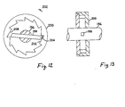
- Figures 12 and 13 illustrate a uni-directional clutch arrangement in which a shaft 196 has secured therein a diametrically extending dog 198 for engaging the inside of an annulus 200 which is formed as a circular internal ratchet.
- the dog 198 is slidable axially within the shaft 196. As the shaft 196 rotates in the direction of the arrow 202, drive is transmitted between the end 204 of the dog 198 and one of the teeth of the ratchet.
- Rotation of the shaft 196 in the opposite direction to arrow 202 causes the dog to ride up the inclined surface 206 and to enter the cutaway region 208 on the opposite side of the ratchet wheel so that there is no tendency for any rotational drive to occur between the shaft 196 and the internal ratchet wheel 200.
- Figure 14 shows more clearly than the views of Figures 1-7 the internal detail of the printing head 26.
- the shafts 80, 82 are formed with reduced axially parallel grooves at their inboard ends one of which is shown in the cross-sectioned half view of Figure 14, at 210.
- Rolling elements such as 212 are located in the grooves and support an annular member such as at 214 forming part of one of the driving wheels 78.
- the design of the grooves and rolling elements and shape of the interior of the annular member 214 is such that rotation of the shaft in one direction transmits drive to the driving wheel 78' whilst in the other direction, to the driving wheel 78". Endless bands containing printing characters are fitted around the driving wheels 78 as previously described.
- indexing wheel 94 co-operates with driving wheel 78'.
- indexing wheels etc are shown in cross-section and the sliding electrical contact between the wheel and the conductive tracks on its associated card 100'.
- the indexing wheels 94', 94" etc are freely rotatable above their centra! supporting axle 220 whilst the cards are non-rotatable relative thereto.
- Figure 15 demonstrates how, after removing the underplate assembly 55 (shown in Figure 7) the underside of the printing head housing 26 can be clearly seen to permit the semi-permanent printing matterto be changed if required.
- This is shown as the rectangular cross-hatched region 222 defining the aperture 224 through which the variable printing characters protrude.
- the region 222 is held in place by six screws 226 and is replaceable by other surrounds as required by removing the screws 226.
Landscapes
- Engineering & Computer Science (AREA)
- Computer Security & Cryptography (AREA)
- Physics & Mathematics (AREA)
- General Physics & Mathematics (AREA)
- Common Mechanisms (AREA)
- Handling Of Sheets (AREA)
- Printers Characterized By Their Purpose (AREA)
- Devices For Checking Fares Or Tickets At Control Points (AREA)
Claims (16)
Applications Claiming Priority (2)
| Application Number | Priority Date | Filing Date | Title |
|---|---|---|---|
| GB8332243 | 1983-12-02 | ||
| GB08332243A GB2150498B (en) | 1983-12-02 | 1983-12-02 | Suspension system for franking machine printing head |
Publications (3)
| Publication Number | Publication Date |
|---|---|
| EP0145404A2 EP0145404A2 (de) | 1985-06-19 |
| EP0145404A3 EP0145404A3 (en) | 1986-02-12 |
| EP0145404B1 true EP0145404B1 (de) | 1988-10-26 |
Family
ID=10552740
Family Applications (1)
| Application Number | Title | Priority Date | Filing Date |
|---|---|---|---|
| EP19840308222 Expired EP0145404B1 (de) | 1983-12-02 | 1984-11-27 | Aufhängung für einen Frankiermaschinendruckkopf |
Country Status (7)
| Country | Link |
|---|---|
| EP (1) | EP0145404B1 (de) |
| JP (1) | JPS60138697A (de) |
| CA (1) | CA1244717A (de) |
| DE (1) | DE3474871D1 (de) |
| GB (1) | GB2150498B (de) |
| PL (1) | PL250666A1 (de) |
| SG (1) | SG1288G (de) |
Families Citing this family (3)
| Publication number | Priority date | Publication date | Assignee | Title |
|---|---|---|---|---|
| US4744554A (en) * | 1986-10-10 | 1988-05-17 | Pitney Bowes Inc. | Deskewing device for mailing machine |
| DE4228765C2 (de) * | 1992-08-28 | 1998-04-09 | Francotyp Postalia Gmbh | Andruckvorrichtung für eine Frankiermaschine mit einer elektrothermischen Druckvorrichtung |
| US5648811A (en) * | 1992-08-28 | 1997-07-15 | Francotyp-Postalia Aktiengesellschaft & Co. | Postage meter |
Family Cites Families (4)
| Publication number | Priority date | Publication date | Assignee | Title |
|---|---|---|---|---|
| GB1132110A (en) * | 1965-11-09 | 1968-10-30 | Pitney Bowes Inc | A platen printing press |
| US4246643A (en) * | 1978-02-13 | 1981-01-20 | Pitney Bowes Inc. | Low cost postage applicator |
| GB2078160B (en) * | 1980-06-24 | 1983-09-07 | Finn Frank John | Press for applying labels to fabrics |
| US4410287A (en) * | 1982-06-01 | 1983-10-18 | M. E. Cunningham Company | Single wheel billet marker |
-
1983
- 1983-12-02 GB GB08332243A patent/GB2150498B/en not_active Expired
-
1984
- 1984-11-27 EP EP19840308222 patent/EP0145404B1/de not_active Expired
- 1984-11-27 DE DE8484308222T patent/DE3474871D1/de not_active Expired
- 1984-11-30 PL PL25066684A patent/PL250666A1/xx unknown
- 1984-12-01 JP JP25493284A patent/JPS60138697A/ja active Pending
- 1984-12-03 CA CA000469147A patent/CA1244717A/en not_active Expired
-
1988
- 1988-01-07 SG SG1288A patent/SG1288G/en unknown
Also Published As
| Publication number | Publication date |
|---|---|
| EP0145404A2 (de) | 1985-06-19 |
| GB2150498B (en) | 1987-06-17 |
| DE3474871D1 (en) | 1988-12-01 |
| JPS60138697A (ja) | 1985-07-23 |
| PL250666A1 (en) | 1985-08-13 |
| SG1288G (en) | 1988-06-17 |
| GB8332243D0 (en) | 1984-01-11 |
| GB2150498A (en) | 1985-07-03 |
| CA1244717A (en) | 1988-11-15 |
| EP0145404A3 (en) | 1986-02-12 |
Similar Documents
| Publication | Publication Date | Title |
|---|---|---|
| US4493252A (en) | Postage printing apparatus having a movable print head in a print drum | |
| US3504622A (en) | Print wheel setting and detenting means with electrical controls therefor | |
| EP0146286B1 (de) | Antriebseinheit für Druckeinrichtungen | |
| US4300847A (en) | Teleprinter having single belt carriage and ribbon drive system | |
| EP0145404B1 (de) | Aufhängung für einen Frankiermaschinendruckkopf | |
| EP0162169B1 (de) | Zum Drucken veränderlicher Daten geeignete Frankiermaschine | |
| US4243331A (en) | Apparatus for adjusting a carriage relative to a platen | |
| US3120800A (en) | Binary printer with decimal display | |
| EP0144207A2 (de) | Frankiermaschine | |
| US3805696A (en) | Ink printing device for use in drum type line printers | |
| EP0239356B1 (de) | Frankiermaschine | |
| US4492160A (en) | Postage printing apparatus having a movable print head and a variable speed drum rotation | |
| US4697517A (en) | Inking apparatus for a mailing machine | |
| JPS6230476B2 (de) | ||
| US3828667A (en) | Label printing machine | |
| GB2213773A (en) | Printwheel detent disengaging apparatus | |
| US4492159A (en) | Postage printing apparatus having a print head with a replaceable ribbon cartridge | |
| US4492158A (en) | Postage printing apparatus having a movable print head and a hollow non-rotating support shaft | |
| US3921518A (en) | High speed printer | |
| US2933038A (en) | Code recording apparatus | |
| US3540373A (en) | Reciprocable platen in selective print wheel printing machine | |
| US3747517A (en) | Type wheel setting and locking means and print actuating means in selective printers | |
| CA1235510A (en) | Postal meter having thermal printer | |
| GB2213774A (en) | Automatic printwheel setting system | |
| US2807999A (en) | Check endorsing apparatus |
Legal Events
| Date | Code | Title | Description |
|---|---|---|---|
| PUAI | Public reference made under article 153(3) epc to a published international application that has entered the european phase |
Free format text: ORIGINAL CODE: 0009012 |
|
| AK | Designated contracting states |
Designated state(s): CH DE FR IT LI |
|
| PUAL | Search report despatched |
Free format text: ORIGINAL CODE: 0009013 |
|
| AK | Designated contracting states |
Designated state(s): CH DE FR IT LI |
|
| 17P | Request for examination filed |
Effective date: 19860318 |
|
| 17Q | First examination report despatched |
Effective date: 19870603 |
|
| RAP1 | Party data changed (applicant data changed or rights of an application transferred) |
Owner name: FRANCOTYP-POSTALIA GMBH |
|
| ITF | It: translation for a ep patent filed | ||
| GRAA | (expected) grant |
Free format text: ORIGINAL CODE: 0009210 |
|
| AK | Designated contracting states |
Kind code of ref document: B1 Designated state(s): CH DE FR IT LI |
|
| REF | Corresponds to: |
Ref document number: 3474871 Country of ref document: DE Date of ref document: 19881201 |
|
| ET | Fr: translation filed | ||
| PLBE | No opposition filed within time limit |
Free format text: ORIGINAL CODE: 0009261 |
|
| STAA | Information on the status of an ep patent application or granted ep patent |
Free format text: STATUS: NO OPPOSITION FILED WITHIN TIME LIMIT |
|
| 26N | No opposition filed | ||
| ITTA | It: last paid annual fee | ||
| PGFP | Annual fee paid to national office [announced via postgrant information from national office to epo] |
Ref country code: DE Payment date: 20020920 Year of fee payment: 19 |
|
| PGFP | Annual fee paid to national office [announced via postgrant information from national office to epo] |
Ref country code: FR Payment date: 20020926 Year of fee payment: 19 |
|
| PGFP | Annual fee paid to national office [announced via postgrant information from national office to epo] |
Ref country code: CH Payment date: 20030227 Year of fee payment: 19 |
|
| PG25 | Lapsed in a contracting state [announced via postgrant information from national office to epo] |
Ref country code: LI Free format text: LAPSE BECAUSE OF NON-PAYMENT OF DUE FEES Effective date: 20031130 Ref country code: CH Free format text: LAPSE BECAUSE OF NON-PAYMENT OF DUE FEES Effective date: 20031130 |
|
| PG25 | Lapsed in a contracting state [announced via postgrant information from national office to epo] |
Ref country code: DE Free format text: LAPSE BECAUSE OF NON-PAYMENT OF DUE FEES Effective date: 20040602 |
|
| REG | Reference to a national code |
Ref country code: CH Ref legal event code: PL |
|
| PG25 | Lapsed in a contracting state [announced via postgrant information from national office to epo] |
Ref country code: FR Free format text: LAPSE BECAUSE OF NON-PAYMENT OF DUE FEES Effective date: 20040730 |
|
| REG | Reference to a national code |
Ref country code: FR Ref legal event code: ST |