EP0145436A2 - Vanne de limitation de pression - Google Patents
Vanne de limitation de pression Download PDFInfo
- Publication number
- EP0145436A2 EP0145436A2 EP84308390A EP84308390A EP0145436A2 EP 0145436 A2 EP0145436 A2 EP 0145436A2 EP 84308390 A EP84308390 A EP 84308390A EP 84308390 A EP84308390 A EP 84308390A EP 0145436 A2 EP0145436 A2 EP 0145436A2
- Authority
- EP
- European Patent Office
- Prior art keywords
- valve
- chamber
- pressure
- valve member
- inlet
- Prior art date
- Legal status (The legal status is an assumption and is not a legal conclusion. Google has not performed a legal analysis and makes no representation as to the accuracy of the status listed.)
- Granted
Links
Images

Classifications
-
- F—MECHANICAL ENGINEERING; LIGHTING; HEATING; WEAPONS; BLASTING
- F16—ENGINEERING ELEMENTS AND UNITS; GENERAL MEASURES FOR PRODUCING AND MAINTAINING EFFECTIVE FUNCTIONING OF MACHINES OR INSTALLATIONS; THERMAL INSULATION IN GENERAL
- F16K—VALVES; TAPS; COCKS; ACTUATING-FLOATS; DEVICES FOR VENTING OR AERATING
- F16K17/00—Safety valves; Equalising valves, e.g. pressure relief valves
- F16K17/02—Safety valves; Equalising valves, e.g. pressure relief valves opening on surplus pressure on one side; closing on insufficient pressure on one side
- F16K17/04—Safety valves; Equalising valves, e.g. pressure relief valves opening on surplus pressure on one side; closing on insufficient pressure on one side spring-loaded
- F16K17/08—Safety valves; Equalising valves, e.g. pressure relief valves opening on surplus pressure on one side; closing on insufficient pressure on one side spring-loaded with special arrangements for providing a large discharge passage
- F16K17/082—Safety valves; Equalising valves, e.g. pressure relief valves opening on surplus pressure on one side; closing on insufficient pressure on one side spring-loaded with special arrangements for providing a large discharge passage with piston
Definitions
- This invention relates to pressure relief valves.
- Pressure relief valves are widely used in fluid pressure systems, particularly hydraulic systems, to limit the pressure which can build up in the system.
- One well-known type of pressure relief valve is the poppet type, in which a spring-loaded poppet valve member controls flow between a pressure inlet and a relief outlet.
- the valve member is biassed to close the inlet, and the spring force is opposed by the pressure at the inlet acting on the valve member.
- the inlet pressure reaches a predetermined level it overcomes the spring force, and the valve cracks open to allow fluid to flow to the outlet.
- the fluid flow forces act on the valve member to open the valve further to allow full flow through the valve.
- the pressure differential across the valve increases to achieve this, and the difference between the inlet pressure at which the valve cracks open - the crack pressure - and that at which full flow is achieved - the full flow pressure - is known as the operating differential.
- the operating differential is undesirable since the increase in inlet pressure results in a greater temperature rise in the system, and more arduous conditions for the seals, and in some systems the operating differential may be substantial, up to 40 bar.
- the fluid flow forces acting on the valve member mean that the inlet pressure at which the valve member reseats - the reseat pressure - is lower than that at which it cracks open. All this results in a substantial variation in the maximum pressure in the system which is undesirable.
- a further problem with this type of valve is that its maximum opening may only be of the order of 0.025mm, so that it is sensitive to dirt.
- a fluid pressure relief valve comprises a housing provided with a pressure inlet and a relief outlet, a chamber in communication with the relief outlet, a valve member for controlling fluid flow between the inlet and the chamber, the valve member having a seating portion adapted to close the inlet and an area responsive to pressure in the chamber, and resilient means biassing the valve member to close the inlet against the pressure applied to the inlet, the valve being so constructed and arranged that on initial opening of the valve pressure builds up in the chamber, producing a force to act on the valve member in opposition to the force produced by the resilient means.
- the pressure in the chamber acting on the valve member moves the valve into its fully open position very rapidly after it has cracked open, so that the operating differential is removed. This avoids the temperature rise in the system, eases the conditions for the seals, and reduces the variation in the maximum pressure. Further, this method of opening the valve means that the maximum opening of the valve can be greater, so that it is not sensitive to dirt.
- the valve means preferably has passage means providing a fluid connection between the chamber and the outlet.
- this passage means provides the only connection between the chamber and the outlet, so that once the valve has opened fully in response to the pressure in the chamber it remains open, and fluid flow to the outlet is through the passage means, the valve, and in particular the passage means, being arranged to provide both a suitable pressure build-up in the chamber, and suitable relief flow characteristics.
- this construction has the disadvantage that fluid flow forces acting on the valve member result in the reseat pressure being significantly less than the crack pressure.
- the chamber is provided with a further connection to the outlet, the flow through which is controlled by the valve member.
- the connection is controlled by movement of the valve member in response to pressure in the chamber, and the force in the resilient means.
- the connection is closed when the inlet is closed, and when it is cracked open, but opens as the valve opens fully.
- the resilient means then acts to return the valve member, closing the connection, but not the inlet.
- Pressure again builds up in the chamber, so the valve member moves to open the connection again, and the cycle repeats. This oscillating motion of the valve member continues until the inlet pressure drops just below the crack pressure, which allows the valve member to reseat on the inlet at the end of its return movement.
- the valve member is able to reseat at this pressure because of the low pressure in the chamber, and the low fluid flow forces on the valve member.
- the pressure passes to the outlet in pulses, and not continuously.
- the valve member moves rapidly in response to the pressure in the chamber, to open the connection, and more slowly on its return, in response to the resilient means.
- the rapid movement creates pressure waves in the fluid, which provide an audible warning that the valve is operative. This is especially marked in hydraulic systems, where a water hammer effect is produced.
- valve member is preferably a spool member which slides in a bore in the housing.
- the seating portion is preferably conical.
- Pressure relief valves in accordance with our invention may be used in vehicle hydraulic systems, in which a fixed displacement engine-driven pump is used to supply an accumulator for a braking system, and an hydraulic suspension system.
- the embodiment with the oscillating valve member is particularly useful, since the valve will reseat without the pump being turned off.
- the pressure relief valve shown in Figure 1 is adapted for incorporation in a fluid pressure system.
- the valve comprises a housing 1 provided with a stepped longitudinal bore 2. At one end of the bore 2 a pressure inlet 3 is defined, while a radial passage 4 leading from the bore 2 communicates with a relief outlet.
- a spool valve member 5 works in the bore 2, and controls fluid flow between the inlet 3 and the outlet passage 4, fluid flow being through a chamber 6 defined in the bore 2 adjacent the inlet 3.
- the chamber 6 is in permanent communication with the outlet passage 4 through a bore 7 and an inclined passage 8 in the spool 5, and the bore 2.
- a conical seating portion 9 on the spool 5 adapted to close the inlet 3 controls fluid flow between the inlet 3 and the chamber 6.
- the valve spool 5 has an area A responsive to pressure in the chamber 6, and is biassed to close the inlet 3 by a spring 10, which works between the end of the bore 7 in the spool 5, and a stationary plug 11 which is sealingly received in the end of the bore 2 remote from the pressure inlet 3.
- the plug 11 has an external screw-thread 23 which cooperates with an internal screw-thread 24 in the bore 2, and is provided with a socket 25 to enable it to be screwed into the bore.
- the pressure relief valve is incorporated in a fluid pressure system (not shown).
- the valve is preferably screwed onto a suitable part by an external screw thread 26.
- the annular end of the housing 1 at the open end of the bore 2 has a pair of slots 27 for a screwdriver, enabling the valve to be installed easily.
- the pressure inlet 3 is connected to the source of pressure for the system, and the outlet passage 4 is connected to a reservoir for the fluid.
- Seals 12, 13 are provided on the housing 1 to seal the connections into the system.
- the inlet pressure On rectification of the fault in the system the inlet pressure will decrease, as will the pressure in chamber 6, and at a second predetermined pressure the spring 10 acts to reseat the valve, with the seating portion 9 closing the inlet 3.
- This second predetermined pressure, the reseat pressure is likely to be significantly lower than the crack pressure, as the fluid forces act on the valve member 5 against the force in the spring 10.
- a poppet valve in general has a large operating differential, that is, it requires a large increase in inlet pressure after cracking open before it reaches full flow.
- This operating differential results in a greater rise in the temperature of the system, in more arduous conditions for the seals, and in variation of the maximum pressure in the system.
- the operating differential is substantially removed, as the pressure in the chamber ensures that the valve opens fully soon after cracking open.
- the valve has a maximum opening of approximately lmm, so that it is not sensitive to dirt, whereas the conventional poppet type is, as its maximum opening is typically 0.025mm.
- the pressure relief valve of Figure 1 may not reseat automatically when the fault in the system is rectified, due to the reseat pressure being lower than the crack pressure.
- the pressure source for the system may therefore need to be made inoperative before the valve will reseat, which is a disadvantage.
- FIG. 2 shows a modification of the valve of Figure 1 which overcomes this disadvantage.
- the valve of Figure 2 includes a second radial passage 14 leading from the bore 2 to the relief outlet, to provide a further connection between the chamber 6 and the outlet. Communication through the connection is controlled by a land 15 on the valve spool 5, and is arranged so that the connection is closed when the inlet is closed and when the valve is cracked open, and opens as the valve opens fully.
- the rest of the construction is the same as that of Figure 1, and corresponding reference numerals have been applied to corresponding parts.
- the valve starts to open at the crack pressure to allow fluid to flow to the outlet via the passage 8, bore 7 and bore 2, and to build up pressure in the chamber 6.
- the valve opens fully in response to the pressure in chamber 6, and the land 15 uncovers the passage 14, so that the pressure in the chamber 6 flows to the relief outlet.
- the reduction in pressure in the chamber 6 enables the spring 10 to return the valve spool 5 so that the land 15 closes the passage 14, but the seating portion 9 does not close the inlet 3. Pressure can then build up again in chamber 6 to open the valve fully again, and to open the passage 14, so that the cycle repeats.
- valve When the inlet pressure drops to just below the crack pressure the valve will reseat on the inlet 3 at the end of its next return movement.
- the valve is able to reseat at this pressure because of the low pressure in the chamber 6, and the low fluid flow forces on the valve spool 5. This means that the valve can reseat automatically when the fault in the system is rectified.
- valve of Figure 2 pressure fluid passes to the relief outlet in pulses, and not continuously.
- the valve spool 5 moves rapidly in response to the pressure in the chamber 6, but more slowly on its return movement in response to the spring 10.
- the rapid movement creates pressure waves, which provide an audible warning that the valve is operative. This is especially marked where the system is hydraulic, and the valve tends to create a water hammer effect.
- the frequency of the oscillation of the valve spool 5 will typically be between 1 and 10Hz.
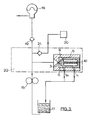
- FIG 3 shows a vehicle hydraulic system incorporating the valve of Figure 2.
- the system comprises a fixed displacement engine-driven pump 16 which draws fluid from a reservoir 17, and pumps it to an accumulator 18 through a one-way valve 19 and to a suspension system 20 through a one-way valve 21.
- the accumulator 18 may operate the braking system (not shown) and other equipment.
- the pressure relief valve is incorporated in a control valve assembly 22, with the inlet 3 connected at a point between the pump 16 and the one-way valves 19, 21.
- the passages 4, 14 are connected to the reservoir 17. It is important for the valve inlet to be connected between the pump 16 and the one-way valves, as this ensures that it operates efficiently to relieve the pressure from the pump 16, and not that stored in the accumulator 18 or the suspension system 20.
- the automatic reseating of the valve of Figure 2 is particularly advantageous in the system of Figure 3, as the engine does not have to be switched off in order to reseat the valve.
Landscapes
- Engineering & Computer Science (AREA)
- General Engineering & Computer Science (AREA)
- Mechanical Engineering (AREA)
- Safety Valves (AREA)
Applications Claiming Priority (2)
| Application Number | Priority Date | Filing Date | Title |
|---|---|---|---|
| GB838332978A GB8332978D0 (en) | 1983-12-09 | 1983-12-09 | Pressure relief valves |
| GB8332978 | 1983-12-09 |
Publications (3)
| Publication Number | Publication Date |
|---|---|
| EP0145436A2 true EP0145436A2 (fr) | 1985-06-19 |
| EP0145436A3 EP0145436A3 (en) | 1985-07-31 |
| EP0145436B1 EP0145436B1 (fr) | 1988-07-20 |
Family
ID=10553115
Family Applications (1)
| Application Number | Title | Priority Date | Filing Date |
|---|---|---|---|
| EP84308390A Expired EP0145436B1 (fr) | 1983-12-09 | 1984-12-04 | Vanne de limitation de pression |
Country Status (3)
| Country | Link |
|---|---|
| EP (1) | EP0145436B1 (fr) |
| DE (1) | DE3472824D1 (fr) |
| GB (2) | GB8332978D0 (fr) |
Cited By (9)
| Publication number | Priority date | Publication date | Assignee | Title |
|---|---|---|---|---|
| EP0322170A3 (en) * | 1987-12-22 | 1989-09-20 | Gas Research Institute | Earth boring apparatus with control valve |
| EP0466081A1 (fr) * | 1990-07-09 | 1992-01-15 | Nippondenso Co., Ltd. | Soupape de sécurité pour dispositif d'injection de combustible |
| US5295469A (en) * | 1990-07-09 | 1994-03-22 | Nippondenso Co., Ltd. | Safety valve for fuel injection apparatus |
| EP0856661A3 (fr) * | 1997-01-30 | 2000-01-26 | Lucas Industries Limited | Pompe de carburant |
| CN102312762A (zh) * | 2010-06-29 | 2012-01-11 | 株式会社电装 | 卸压阀和带有这种阀的高压泵 |
| JP2014219029A (ja) * | 2013-05-02 | 2014-11-20 | 株式会社山田製作所 | リリーフ弁構造 |
| JP2014219028A (ja) * | 2013-05-02 | 2014-11-20 | 株式会社山田製作所 | リリーフ弁構造 |
| JP2014219027A (ja) * | 2013-05-02 | 2014-11-20 | 株式会社山田製作所 | リリーフ弁構造 |
| US9708872B2 (en) | 2013-06-19 | 2017-07-18 | Wwt North America Holdings, Inc | Clean out sub |
Family Cites Families (12)
| Publication number | Priority date | Publication date | Assignee | Title |
|---|---|---|---|---|
| GB406720A (en) * | 1932-07-27 | 1934-02-27 | Varley Pumps And Engineering L | Improvements relating to rotary pumps |
| GB546913A (en) * | 1941-02-03 | 1942-08-05 | Thomas Graham Farish | Improvements in or relating to steam or like pressure cookers, digesters and the like |
| US2594626A (en) * | 1946-09-09 | 1952-04-29 | Clarence E Earle | Safety valve |
| GB711606A (en) * | 1950-07-28 | 1954-07-07 | Bendix Aviat Corp | Improvements in or relating to relief valves for use in hydraulic systems |
| GB858948A (en) * | 1957-09-17 | 1961-01-18 | Dowty Fuel Syst Ltd | Improvements in liquid spray nozzles |
| CH403358A (de) * | 1961-04-01 | 1965-11-30 | Bratislavske Elektrotechnicke | Regelvorrichtung zum Festlegen zweier nachfolgender Drücke in hydraulisch angetriebenen Maschinen, insbesondere Maschinen für hydraulische Schweisspressung bei elektrischer Widerstandsschweissung |
| FR1498933A (fr) * | 1966-11-09 | 1967-10-20 | Soupape de sûreté et de décharge simplifiée | |
| FR1582151A (fr) * | 1968-06-27 | 1969-09-26 | ||
| GB1306812A (en) * | 1968-11-11 | 1973-02-14 | Flexian Hydraulics Ltd | Safety valves |
| ES445020A1 (es) * | 1976-02-10 | 1977-06-01 | Bendiberica Sa | Perfeccionamientos en valvulas de limitacion de presion. |
| US4116212A (en) * | 1976-06-14 | 1978-09-26 | Pall Corporation | Unidirectional flow control valve |
| DE3322771A1 (de) * | 1983-06-24 | 1985-01-03 | Alfred Teves Gmbh, 6000 Frankfurt | Ventilanordnung zur begrenzung des drucks in einem drucksystem |
-
1983
- 1983-12-09 GB GB838332978A patent/GB8332978D0/en active Pending
-
1984
- 1984-12-04 EP EP84308390A patent/EP0145436B1/fr not_active Expired
- 1984-12-04 GB GB08430561A patent/GB2151339B/en not_active Expired
- 1984-12-04 DE DE8484308390T patent/DE3472824D1/de not_active Expired
Cited By (10)
| Publication number | Priority date | Publication date | Assignee | Title |
|---|---|---|---|---|
| EP0322170A3 (en) * | 1987-12-22 | 1989-09-20 | Gas Research Institute | Earth boring apparatus with control valve |
| EP0466081A1 (fr) * | 1990-07-09 | 1992-01-15 | Nippondenso Co., Ltd. | Soupape de sécurité pour dispositif d'injection de combustible |
| US5295469A (en) * | 1990-07-09 | 1994-03-22 | Nippondenso Co., Ltd. | Safety valve for fuel injection apparatus |
| EP0856661A3 (fr) * | 1997-01-30 | 2000-01-26 | Lucas Industries Limited | Pompe de carburant |
| CN102312762A (zh) * | 2010-06-29 | 2012-01-11 | 株式会社电装 | 卸压阀和带有这种阀的高压泵 |
| CN102312762B (zh) * | 2010-06-29 | 2013-11-13 | 株式会社电装 | 卸压阀和带有这种阀的高压泵 |
| JP2014219029A (ja) * | 2013-05-02 | 2014-11-20 | 株式会社山田製作所 | リリーフ弁構造 |
| JP2014219028A (ja) * | 2013-05-02 | 2014-11-20 | 株式会社山田製作所 | リリーフ弁構造 |
| JP2014219027A (ja) * | 2013-05-02 | 2014-11-20 | 株式会社山田製作所 | リリーフ弁構造 |
| US9708872B2 (en) | 2013-06-19 | 2017-07-18 | Wwt North America Holdings, Inc | Clean out sub |
Also Published As
| Publication number | Publication date |
|---|---|
| DE3472824D1 (en) | 1988-08-25 |
| GB2151339B (en) | 1986-10-15 |
| EP0145436A3 (en) | 1985-07-31 |
| GB8332978D0 (en) | 1984-01-18 |
| GB2151339A (en) | 1985-07-17 |
| EP0145436B1 (fr) | 1988-07-20 |
| GB8430561D0 (en) | 1985-01-09 |
Similar Documents
| Publication | Publication Date | Title |
|---|---|---|
| US4058287A (en) | Pilot-operated valve having constant closing rate | |
| US4629002A (en) | Equalizing means for a subsurface well safety valve | |
| EP0515215B1 (fr) | Purgeur automatique | |
| CA2282037A1 (fr) | Systeme de commande de robinet | |
| EP0145436A2 (fr) | Vanne de limitation de pression | |
| US6131606A (en) | Moving check valve seat providing high pressure relief | |
| US4827972A (en) | Priority flow control valve | |
| US4716928A (en) | Pressure-relief valve devices | |
| CA2186063C (fr) | Soupape de decharge et de derivation pour pompes et canalisations | |
| KR900002882B1 (ko) | 배수장치용 콘트롤 스톱 | |
| US20040144938A1 (en) | Pressure compensated pilot operated check valve | |
| EP1252557B1 (fr) | Systeme de soupape de retour comprenant une soupape pilote pourvue d'un mecanisme d'amortissement radial | |
| US4817660A (en) | Pressure regulating valve | |
| US4665942A (en) | Hydraulic pressure fuse | |
| US1218567A (en) | Automatic valve device for distributing liquid under pressure. | |
| US5168893A (en) | Block and bleed valve | |
| GB2142123A (en) | Pressure limiting valve | |
| US8141579B2 (en) | Valve with cushioned opening system | |
| JPS6011689A (ja) | ストロ−ク制御弁 | |
| RU2094685C1 (ru) | Электромагнитный клапан | |
| WO1999009341A1 (fr) | Soupape pilotee de modulation sans ecoulement | |
| SU1629672A1 (ru) | Предохранительный клапан | |
| EP0305379B1 (fr) | Soupape de securite | |
| SU1418539A1 (ru) | Компенсатор гидравлического удара | |
| GB1595414A (en) | Valves |
Legal Events
| Date | Code | Title | Description |
|---|---|---|---|
| PUAI | Public reference made under article 153(3) epc to a published international application that has entered the european phase |
Free format text: ORIGINAL CODE: 0009012 |
|
| PUAL | Search report despatched |
Free format text: ORIGINAL CODE: 0009013 |
|
| AK | Designated contracting states |
Designated state(s): DE FR IT |
|
| AK | Designated contracting states |
Designated state(s): DE FR IT |
|
| 17P | Request for examination filed |
Effective date: 19860107 |
|
| 17Q | First examination report despatched |
Effective date: 19861215 |
|
| GRAA | (expected) grant |
Free format text: ORIGINAL CODE: 0009210 |
|
| AK | Designated contracting states |
Kind code of ref document: B1 Designated state(s): DE FR IT |
|
| ITF | It: translation for a ep patent filed | ||
| REF | Corresponds to: |
Ref document number: 3472824 Country of ref document: DE Date of ref document: 19880825 |
|
| ET | Fr: translation filed | ||
| PLBE | No opposition filed within time limit |
Free format text: ORIGINAL CODE: 0009261 |
|
| STAA | Information on the status of an ep patent application or granted ep patent |
Free format text: STATUS: NO OPPOSITION FILED WITHIN TIME LIMIT |
|
| 26N | No opposition filed | ||
| ITTA | It: last paid annual fee | ||
| PGFP | Annual fee paid to national office [announced via postgrant information from national office to epo] |
Ref country code: FR Payment date: 19901120 Year of fee payment: 7 |
|
| PGFP | Annual fee paid to national office [announced via postgrant information from national office to epo] |
Ref country code: DE Payment date: 19910208 Year of fee payment: 7 |
|
| PG25 | Lapsed in a contracting state [announced via postgrant information from national office to epo] |
Ref country code: FR Effective date: 19920831 |
|
| PG25 | Lapsed in a contracting state [announced via postgrant information from national office to epo] |
Ref country code: DE Effective date: 19920901 |
|
| REG | Reference to a national code |
Ref country code: FR Ref legal event code: ST |