EP0145456A2 - Ausblas-Preventer mit Abschervorrichtung - Google Patents
Ausblas-Preventer mit Abschervorrichtung Download PDFInfo
- Publication number
- EP0145456A2 EP0145456A2 EP84308483A EP84308483A EP0145456A2 EP 0145456 A2 EP0145456 A2 EP 0145456A2 EP 84308483 A EP84308483 A EP 84308483A EP 84308483 A EP84308483 A EP 84308483A EP 0145456 A2 EP0145456 A2 EP 0145456A2
- Authority
- EP
- European Patent Office
- Prior art keywords
- ram
- string
- blade
- bore
- shearing
- Prior art date
- Legal status (The legal status is an assumption and is not a legal conclusion. Google has not performed a legal analysis and makes no representation as to the accuracy of the status listed.)
- Granted
Links
Images



Classifications
-
- E—FIXED CONSTRUCTIONS
- E21—EARTH OR ROCK DRILLING; MINING
- E21B—EARTH OR ROCK DRILLING; OBTAINING OIL, GAS, WATER, SOLUBLE OR MELTABLE MATERIALS OR A SLURRY OF MINERALS FROM WELLS
- E21B33/00—Sealing or packing boreholes or wells
- E21B33/02—Surface sealing or packing
- E21B33/03—Well heads; Setting-up thereof
- E21B33/06—Blow-out preventers, i.e. apparatus closing around a drill pipe, e.g. annular blow-out preventers
- E21B33/061—Ram-type blow-out preventers, e.g. with pivoting rams
- E21B33/062—Ram-type blow-out preventers, e.g. with pivoting rams with sliding rams
- E21B33/063—Ram-type blow-out preventers, e.g. with pivoting rams with sliding rams for shearing drill pipes
-
- E—FIXED CONSTRUCTIONS
- E21—EARTH OR ROCK DRILLING; MINING
- E21B—EARTH OR ROCK DRILLING; OBTAINING OIL, GAS, WATER, SOLUBLE OR MELTABLE MATERIALS OR A SLURRY OF MINERALS FROM WELLS
- E21B29/00—Cutting or destroying pipes, packers, plugs or wire lines, located in boreholes or wells, e.g. cutting of damaged pipes, of windows; Deforming of pipes in boreholes or wells; Reconditioning of well casings while in the ground
- E21B29/08—Cutting or deforming pipes to control fluid flow
-
- Y—GENERAL TAGGING OF NEW TECHNOLOGICAL DEVELOPMENTS; GENERAL TAGGING OF CROSS-SECTIONAL TECHNOLOGIES SPANNING OVER SEVERAL SECTIONS OF THE IPC; TECHNICAL SUBJECTS COVERED BY FORMER USPC CROSS-REFERENCE ART COLLECTIONS [XRACs] AND DIGESTS
- Y10—TECHNICAL SUBJECTS COVERED BY FORMER USPC
- Y10T—TECHNICAL SUBJECTS COVERED BY FORMER US CLASSIFICATION
- Y10T83/00—Cutting
- Y10T83/869—Means to drive or to guide tool
- Y10T83/8821—With simple rectilinear reciprocating motion only
- Y10T83/8854—Progressively cutting
Definitions
- U.S. Patent No. 4,313,496 discloses a shearing type of blowout preventer which is adapted to shear through drill collars of a drill string and is provided with arms secured to the sides of the shear blades which interengage and function to provide a force to resist the forces tending to vertically separate the cutting blades and to fill the space of the guideways outside the vertical bore of the preventer to prevent the forcing of the member being cut into this space.
- U.S. Patent Nos. 3,736,982, 3,817,326, 4,132,265, 4,132,266 and 4,132,267 each of which disclose shear rams which engage and shear pipe extending therethrough and crush the upper end of the fish substantially flat after it is sheared and shearing is accomplished with the use of a very substantial amount of force.
- U.S. Patent No. 3,863,667 discloses a combination double pipe shearing and plug device mounted on a partially cut pipe line so that a section of the pipe can be removed and then closed with the plug. The cutting edges are pointed but must cut the pipe without deforming it in order to maintain the seal between the housing and the pipe.
- the present invention relates to an improved shearing type of blowout preventer having shear rams which are so shaped that they do not flatten a production string when it is sheared.
- the improved blowout preventer includes a body having a vertical bore therethrough with opposed, aligned ram guideways extending outwardly from said bores, a shear ram assembly in each of said guideways and having means for moving the ram assemblies inwardly into the bore and outwardly into the guideways, one of said shear ram assemblies having a lower blade profile including piercing means, such as two nodes or points with the space between the nodes being sufficient to accommodate the thickness of the pipe walls together with a solid bar inside the pipe and the other ram assembly having an upper shear blade with a recess below the blade to constrain the sheared end of the pipe so that the extreme ends of the pipe are bent back to maintain a nominal clearance space between the pipe and the diameter of the bore of the preventer body.
- An object of the present invention is to provide an improved shearing type of blowout preventer which can be installed on a production well and which will close on a production string and shear such string but allow the upper end of the lower portion of the sheared string to be sufficiently open to receive fluids to kill the well.
- Another object of the present invention is to provide an improved shearing type of blowout preventer which shears pipe when its rams are closed thereon but controls the shape of the sheared string so that it may be readily engaged by an overshot type retrieving tool.
- a further object of the prevent invention is to provide an improved shearing ram-type blowout preventer having improved shearing of a string extending therethrough to prevent the string from being flattened outward against the bore of the preventer body.
- Still another object is to provide an improved shearing ram-type blowout preventer which shears a pipe string extending therethrough with considerably less force than has been used with the prior art devices.
- a still further object of the present invention is to provide an improved shearing type of blowout preventer in which the shearing action also shears a string or wire line extending through the interior of the string being sheared.
- Still a further object of the present invention is to provide an improved shearing type of blowout preventer which allows larger sized pipe to be sheared therein.
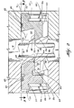
- blowout preventer 10 includes body 12 having a central bore 14 extending vertically therethrough and ram guideways 16 which are aligned and extend outwardly through body 12 from opposite sides of bore 14.
- production tubing string 18 is shown extending through bore 14 in its normal position and with ram assemblies 20 and 22 positioned in their retracted position within guideways 16.
- Production tubing string 18 is supported below blowout preventer 10 in the normal manner so that when it is sheared it does not drop below the blowout preventer 10.
- Suitable means 24 is provided for moving ram assemblies 20 and 22 inwardly and outwardly in their respective guideway 16.
- Such means includes the usual ram piston which is connected to its ram by connecting rod 26.
- Flanges 28 on the ends of connecting rod 26 engage in slots 30 in the rear of ram bodies 32 and 34 to provide connection of ram assemblies 20 and 22 from their moving means 24.
- Blowout preventer 10 includes shearing means for the cutting of tubing 18, when it is desirable such as when there is a well blowout.
- the cutting of the tubing provides the means for controlling of a well blowout.
- Ram assembly 20 shown in the right hand side of the drawings and ram assembly 22 shown in the left hand side of the drawings each include a shear blade.
- Lower shear blade 36 is integral with (or if hardened blades are desired) is secured to the face of body 32 of ram assembly 22 and upper shear blade 38 is a part of or secured to the face of body 34 of ram assembly 20.
- each of ram assemblies 20 and 22 include top seals 40 which are positioned in the grooves 42 which extend across the top of ram bodies 32 and 34 from side to side and provide a continuation of side packings 44 and 46 on ram bodies 32 and 34, respectively.
- Lower shear blade 36 is integral with ram body 32, has a flat upper surface 48 for sealing, as hereinafter explained, and has side packings 44 which are secured to body 32 by a stud (not shown) which is secured to the side metal portion 50 of side packing 44 and extends through body 32 and is secured thereto by nut 52 (FIGURE 6).
- Side packings 44 which are positioned on each side of body 32 are similar but are the reverse image of each other.
- Side packings 44 each include resilient packing 54 and metal portion 50 which extends forwardly at each side of body 32 above surface 48.
- Resilient packing 54 extends from a position in engagement with the lower end of top seal 40 forward to a position to coact with and seal with the surface seal 66 which engages surface 48 on body 32.
- Metal portions 50 of side packings 54 provide rigid side projections at each side of body 32 which coact with recess 56 in the top portion of body 32 to provide a recess to contain the sheared top portion of a string which has been sheared by rams 20 and 22.
- Lower shear blade 36 includes a shearing edge which functions as a piercing means. Such piercing means includes forward facing nodes 58 which initially engage string 18 as is clearly shown in FIGURE 3.
- Ram body 32 includes lower mud slot 60 which extends along the underside of body 32 to provide a communication to the rear of ram assembly 20 to balance the well pressure exerted on the face of the rams when the rams are closed.
- Upper shear blade 38 is integral with ram body 34 and has a concave shape to its face and surface 62 thereunder which is flat and has groove 64 extending completely across surface 62. Packing seal 66 is positioned in groove 64.
- Side packings 46 are provided on each side of shear blade 38 and are secured to ram body 34 by studs (not shown) which are secured to metal portion 70 of side packing 46 and extend through body 34 with nut 72 threaded on the end of stud to secure side packings 46.
- Side packings 46 each include metal portion 70 and resilient packing 74 which is in engagement with the side portions of top seal 40. The resilient portions of side packings 44 and 46 coact with top seals 40 and packing seal 66 to provide a complete seal across bore 14 when ram assemblies 20 and 22 are closed.
- Ram body 34 below shear blade 38 has a concave shape and coacts with side packings 46 to provide concave recess 78 in which the lower portion of string 18 is positioned after shearing.
- Mud slot 80 extends along the lower portion of ram body 34 to provide communication to the rear of ram body 34. Opening 82 is provided at the central portion of recess 78 to provide a flow passage through which fluids may flow after closing and shearing of string 18 to conduct control fluids to the interior of string 18.
- shear blade 38 is shaped to center string 18 so that on further movement of the ram assemblies, the shearing is started by a penetration of string 18 by nodes 58. Such initial penetration is believed to be the reason that the improved device of the present invention requires much less force for shearing of a tubing or pipe string that the devices of the prior art.
- the shape of the ram assemblies constrain the upper end of the lower sheared string to have a shape that is suitable for engagement by an overshot retrieving tool.
- the improvement in controlling the sheared shape of the upper portion of the sheared string results from the shape of the shear blades and the recesses formed by the inner faces of the ram bodies and the side packings.
- These configurations provide a support of semicircular shape for the side of string opposite the lower shear blade nodes so that it is not deformed in a manner which would prevent fluid circulation after shearing is complete.
- this structure controls the shape of the sheared string to keep it within bore 14 and so that it is easily engaged by a tool after fluid control of the well is attained.
Landscapes
- Life Sciences & Earth Sciences (AREA)
- Engineering & Computer Science (AREA)
- Geology (AREA)
- Mining & Mineral Resources (AREA)
- Environmental & Geological Engineering (AREA)
- Fluid Mechanics (AREA)
- General Life Sciences & Earth Sciences (AREA)
- Geochemistry & Mineralogy (AREA)
- Physics & Mathematics (AREA)
- Shearing Machines (AREA)
- Perforating, Stamping-Out Or Severing By Means Other Than Cutting (AREA)
- Multiple-Way Valves (AREA)
- Excavating Of Shafts Or Tunnels (AREA)
- Scissors And Nippers (AREA)
- Respiratory Apparatuses And Protective Means (AREA)
- Safety Valves (AREA)
- Absorbent Articles And Supports Therefor (AREA)
- Drilling Tools (AREA)
- Processing Of Stones Or Stones Resemblance Materials (AREA)
- Encapsulation Of And Coatings For Semiconductor Or Solid State Devices (AREA)
- Auxiliary Devices For And Details Of Packaging Control (AREA)
- Placing Or Removing Of Piles Or Sheet Piles, Or Accessories Thereof (AREA)
- Harvester Elements (AREA)
- Control Of Cutting Processes (AREA)
Priority Applications (1)
| Application Number | Priority Date | Filing Date | Title |
|---|---|---|---|
| AT84308483T ATE56247T1 (de) | 1983-12-14 | 1984-12-06 | Ausblas-preventer mit abschervorrichtung. |
Applications Claiming Priority (2)
| Application Number | Priority Date | Filing Date | Title |
|---|---|---|---|
| US06/560,941 US4537250A (en) | 1983-12-14 | 1983-12-14 | Shearing type blowout preventer |
| US560941 | 2000-04-28 |
Publications (3)
| Publication Number | Publication Date |
|---|---|
| EP0145456A2 true EP0145456A2 (de) | 1985-06-19 |
| EP0145456A3 EP0145456A3 (en) | 1986-02-05 |
| EP0145456B1 EP0145456B1 (de) | 1990-09-05 |
Family
ID=24240010
Family Applications (1)
| Application Number | Title | Priority Date | Filing Date |
|---|---|---|---|
| EP84308483A Expired - Lifetime EP0145456B1 (de) | 1983-12-14 | 1984-12-06 | Ausblas-Preventer mit Abschervorrichtung |
Country Status (10)
| Country | Link |
|---|---|
| US (1) | US4537250A (de) |
| EP (1) | EP0145456B1 (de) |
| JP (1) | JPS60144494A (de) |
| AT (1) | ATE56247T1 (de) |
| AU (1) | AU567378B2 (de) |
| CA (1) | CA1212899A (de) |
| DE (1) | DE3483140D1 (de) |
| MX (1) | MX160883A (de) |
| NO (1) | NO167595C (de) |
| SG (1) | SG44691G (de) |
Cited By (8)
| Publication number | Priority date | Publication date | Assignee | Title |
|---|---|---|---|---|
| GB2226834A (en) * | 1989-01-05 | 1990-07-11 | Otis Eng Co | System for handling reeled tubing. |
| WO2011148190A3 (en) * | 2010-05-28 | 2012-01-19 | National Oilwell Varco, L.P. | Tubular severing system and method of using same |
| WO2012024208A3 (en) * | 2010-08-17 | 2012-06-07 | T-3 Property Holdings, Inc. | Blowout preventer with shearing blades and method |
| US8424607B2 (en) | 2006-04-25 | 2013-04-23 | National Oilwell Varco, L.P. | System and method for severing a tubular |
| US8602102B2 (en) | 2006-04-25 | 2013-12-10 | National Oilwell Varco, L.P. | Blowout preventers and methods of use |
| US8720565B2 (en) | 2006-04-25 | 2014-05-13 | National Oilwell Varco, L.P. | Tubular severing system and method of using same |
| US8720564B2 (en) | 2006-04-25 | 2014-05-13 | National Oilwell Varco, L.P. | Tubular severing system and method of using same |
| WO2019016194A3 (de) * | 2017-07-17 | 2019-04-04 | Gustav Klauke Gmbh | Arbeitsgerät zum schneiden eines werkstücks |
Families Citing this family (42)
| Publication number | Priority date | Publication date | Assignee | Title |
|---|---|---|---|---|
| US4646825A (en) * | 1986-01-02 | 1987-03-03 | Winkle Denzal W Van | Blowout preventer, shear ram, shear blade and seal therefor |
| US5360061A (en) * | 1992-10-14 | 1994-11-01 | Womble Lee M | Blowout preventer with tubing shear rams |
| US5400857A (en) * | 1993-12-08 | 1995-03-28 | Varco Shaffer, Inc. | Oilfield tubular shear ram and method for blowout prevention |
| US5515916A (en) * | 1995-03-03 | 1996-05-14 | Stewart & Stevenson Services, Inc. | Blowout preventer |
| US6173770B1 (en) | 1998-11-20 | 2001-01-16 | Hydril Company | Shear ram for ram-type blowout preventer |
| US6158505A (en) * | 1999-08-30 | 2000-12-12 | Cooper Cameron Corporation | Blade seal for a shearing blind ram in a ram type blowout preventer |
| US6244336B1 (en) * | 2000-03-07 | 2001-06-12 | Cooper Cameron Corporation | Double shearing rams for ram type blowout preventer |
| US7086467B2 (en) * | 2001-12-17 | 2006-08-08 | Schlumberger Technology Corporation | Coiled tubing cutter |
| US6719042B2 (en) | 2002-07-08 | 2004-04-13 | Varco Shaffer, Inc. | Shear ram assembly |
| US7354026B2 (en) * | 2004-08-17 | 2008-04-08 | Cameron International Corporation | Unitary blade seal for a shearing blind ram in a ram type blowout preventer |
| US7703739B2 (en) * | 2004-11-01 | 2010-04-27 | Hydril Usa Manufacturing Llc | Ram BOP shear device |
| US7234530B2 (en) * | 2004-11-01 | 2007-06-26 | Hydril Company Lp | Ram BOP shear device |
| GB0425117D0 (en) * | 2004-11-13 | 2004-12-15 | Cromar Ltd | Improved valve |
| US20060144586A1 (en) * | 2004-12-30 | 2006-07-06 | Cooper Cameron Corporation | Shearing blind ram assembly with a fish pocket |
| NO323497B1 (no) * | 2005-01-27 | 2007-05-29 | Aker Subsea As | Anodning ved en avskjaererventil |
| US7331562B2 (en) * | 2005-11-07 | 2008-02-19 | Varco I/P, Inc. | Blowout preventer with breech assembly |
| US20080105436A1 (en) * | 2006-11-02 | 2008-05-08 | Schlumberger Technology Corporation | Cutter Assembly |
| US8844898B2 (en) | 2009-03-31 | 2014-09-30 | National Oilwell Varco, L.P. | Blowout preventer with ram socketing |
| US8261829B2 (en) * | 2009-07-29 | 2012-09-11 | Hydrus Corporation, Inc. | Well fishing method and system |
| WO2012006457A1 (en) | 2010-07-09 | 2012-01-12 | National Oilwell Varco, L.P. | Circulation sub and method for using same |
| US8544538B2 (en) | 2010-07-19 | 2013-10-01 | National Oilwell Varco, L.P. | System and method for sealing a wellbore |
| US8540017B2 (en) | 2010-07-19 | 2013-09-24 | National Oilwell Varco, L.P. | Method and system for sealing a wellbore |
| GB2482893B (en) * | 2010-08-18 | 2017-08-16 | Humm Gary | Shear valve |
| US8807219B2 (en) | 2010-09-29 | 2014-08-19 | National Oilwell Varco, L.P. | Blowout preventer blade assembly and method of using same |
| SG193346A1 (en) | 2011-03-09 | 2013-10-30 | Nat Oilwell Varco Lp | Method and apparatus for sealing a wellbore |
| US8464785B2 (en) * | 2011-06-14 | 2013-06-18 | Hydril Usa Manufacturing Llc | Pipe guide arms for blind shear rams |
| CN104411917B (zh) | 2012-06-20 | 2018-01-09 | 国际壳牌研究有限公司 | 一种用于防喷器的电磁致动器 |
| WO2014130703A2 (en) | 2013-02-21 | 2014-08-28 | National Oilwell Varco, L.P. | Blowout preventer monitoring system and method of using same |
| US9752411B2 (en) | 2013-07-26 | 2017-09-05 | National Oilwell DHT, L.P. | Downhole activation assembly with sleeve valve and method of using same |
| US9580987B2 (en) | 2014-03-28 | 2017-02-28 | National Oilwell Varco, L.P. | Spherical blowout preventer with energizeable packer seal and method of using same |
| US9879498B2 (en) * | 2015-04-21 | 2018-01-30 | Axon Pressure Products, Inc. | Shear block design for blowout preventer |
| GB201508907D0 (en) * | 2015-05-26 | 2015-07-01 | Maritime Promeco As | Wellbore control device |
| AU2017330160B2 (en) * | 2016-09-26 | 2023-02-23 | Electrical Subsea & Drilling As | Wellbore control device |
| WO2019199494A1 (en) * | 2018-04-10 | 2019-10-17 | Hydril USA Distribution LLC | Wireline blind shear ram |
| US10683727B1 (en) * | 2018-12-13 | 2020-06-16 | Cameron International Corporation | Valve for mineral extraction systems |
| WO2020219137A1 (en) | 2019-04-21 | 2020-10-29 | Cameron International Corporation | Blowout preventer with multiple application ram blades |
| US12139991B2 (en) | 2019-04-21 | 2024-11-12 | Schlumberger Technology Corporation | Blowout preventer shearing ram |
| US11286740B2 (en) | 2019-04-21 | 2022-03-29 | Schlumberger Technology Corporation | Blowout preventer shearing ram |
| USD973734S1 (en) * | 2019-08-06 | 2022-12-27 | Nxl Technologies Inc. | Blind shear |
| US11391108B2 (en) | 2020-06-03 | 2022-07-19 | Schlumberger Technology Corporation | Shear ram for a blowout preventer |
| US11613955B2 (en) * | 2020-07-15 | 2023-03-28 | Baker Hughes Oilfield Operations Llc | Shear ram with vertical shear control |
| US12247456B1 (en) | 2023-08-24 | 2025-03-11 | Schlumberger Technology Corporation | Blowout preventer system and method utilizing shear ram buttress |
Family Cites Families (11)
| Publication number | Priority date | Publication date | Assignee | Title |
|---|---|---|---|---|
| US3040611A (en) * | 1956-11-15 | 1962-06-26 | Duralumin | Guillotine shears |
| FR1281931A (fr) * | 1960-11-02 | 1962-01-19 | Perfectionnements aux tronçonneuses de tubes | |
| US3716068A (en) * | 1971-06-11 | 1973-02-13 | F Addison | Surface controlled blowout arrester |
| US3766979A (en) * | 1972-04-20 | 1973-10-23 | J Petrick | Well casing cutter and sealer |
| US3817326A (en) * | 1972-06-16 | 1974-06-18 | Cameron Iron Works Inc | Ram-type blowout preventer |
| US3863667A (en) * | 1973-03-21 | 1975-02-04 | Pipe Line Development Co | Combined shear head and housing plug |
| US4132265A (en) * | 1978-04-06 | 1979-01-02 | Cameron Iron Works, Inc. | Pipe shearing ram assembly for blowout preventer |
| US4215749A (en) * | 1979-02-05 | 1980-08-05 | Acf Industries, Incorporated | Gate valve for shearing workover lines to permit shutting in of a well |
| JPS563128A (en) * | 1979-06-13 | 1981-01-13 | Yanagihara Kogyo Kk | Cutter for cutting pipe and preparation of pipe having concave arclike end surface |
| US4313496A (en) * | 1980-04-22 | 1982-02-02 | Cameron Iron Works, Inc. | Wellhead shearing apparatus |
| US4347898A (en) * | 1980-11-06 | 1982-09-07 | Cameron Iron Works, Inc. | Shear ram blowout preventer |
-
1983
- 1983-12-14 US US06/560,941 patent/US4537250A/en not_active Expired - Lifetime
-
1984
- 1984-11-30 AU AU36053/84A patent/AU567378B2/en not_active Ceased
- 1984-12-06 DE DE8484308483T patent/DE3483140D1/de not_active Expired - Lifetime
- 1984-12-06 EP EP84308483A patent/EP0145456B1/de not_active Expired - Lifetime
- 1984-12-06 AT AT84308483T patent/ATE56247T1/de not_active IP Right Cessation
- 1984-12-13 NO NO845009A patent/NO167595C/no not_active IP Right Cessation
- 1984-12-13 MX MX203715A patent/MX160883A/es unknown
- 1984-12-13 CA CA000469981A patent/CA1212899A/en not_active Expired
- 1984-12-14 JP JP59264378A patent/JPS60144494A/ja active Granted
-
1991
- 1991-06-15 SG SG44691A patent/SG44691G/en unknown
Cited By (17)
| Publication number | Priority date | Publication date | Assignee | Title |
|---|---|---|---|---|
| GB2226834B (en) * | 1989-01-05 | 1993-02-03 | Otis Eng Co | System for handling reeled tubing |
| GB2226834A (en) * | 1989-01-05 | 1990-07-11 | Otis Eng Co | System for handling reeled tubing. |
| US8602102B2 (en) | 2006-04-25 | 2013-12-10 | National Oilwell Varco, L.P. | Blowout preventers and methods of use |
| US8720564B2 (en) | 2006-04-25 | 2014-05-13 | National Oilwell Varco, L.P. | Tubular severing system and method of using same |
| US8720567B2 (en) | 2006-04-25 | 2014-05-13 | National Oilwell Varco, L.P. | Blowout preventers for shearing a wellbore tubular |
| US8424607B2 (en) | 2006-04-25 | 2013-04-23 | National Oilwell Varco, L.P. | System and method for severing a tubular |
| US8720565B2 (en) | 2006-04-25 | 2014-05-13 | National Oilwell Varco, L.P. | Tubular severing system and method of using same |
| AU2011256976B2 (en) * | 2010-05-28 | 2015-05-21 | National Oilwell Varco, L.P. | Tubular severing system and method of using same |
| WO2011148191A3 (en) * | 2010-05-28 | 2012-01-19 | National Oilwell Varco, L.P. | Tubular severing system and method of using same |
| WO2011148190A3 (en) * | 2010-05-28 | 2012-01-19 | National Oilwell Varco, L.P. | Tubular severing system and method of using same |
| RU2559238C2 (ru) * | 2010-05-28 | 2015-08-10 | НЭШНЛ ОЙЛВЕЛЛ ВАРКО, Эл.Пи. | Система отрезания трубного изделия и способ ее использования |
| US8443880B1 (en) | 2010-08-17 | 2013-05-21 | T-3 Property Holdings, Inc. | Blowout preventer with shearing blades |
| US8443879B2 (en) | 2010-08-17 | 2013-05-21 | T-3 Property Holdings, Inc. | Blowout preventer with shearing blades |
| WO2012024208A3 (en) * | 2010-08-17 | 2012-06-07 | T-3 Property Holdings, Inc. | Blowout preventer with shearing blades and method |
| EA026250B1 (ru) * | 2010-08-17 | 2017-03-31 | Т-3 Проперти Холдингс, Инк. | Противовыбросовый превентор с лезвиями среза и способ его использования |
| WO2019016194A3 (de) * | 2017-07-17 | 2019-04-04 | Gustav Klauke Gmbh | Arbeitsgerät zum schneiden eines werkstücks |
| US11684984B2 (en) | 2017-07-17 | 2023-06-27 | Gustav Klauke Gmbh | Tool for cutting a workpiece |
Also Published As
| Publication number | Publication date |
|---|---|
| AU567378B2 (en) | 1987-11-19 |
| AU3605384A (en) | 1985-06-20 |
| EP0145456B1 (de) | 1990-09-05 |
| CA1212899A (en) | 1986-10-21 |
| JPH052800B2 (de) | 1993-01-13 |
| NO845009L (no) | 1985-06-17 |
| JPS60144494A (ja) | 1985-07-30 |
| NO167595B (no) | 1991-08-12 |
| DE3483140D1 (de) | 1990-10-11 |
| US4537250A (en) | 1985-08-27 |
| NO167595C (no) | 1991-11-20 |
| MX160883A (es) | 1990-06-07 |
| SG44691G (en) | 1991-07-26 |
| ATE56247T1 (de) | 1990-09-15 |
| EP0145456A3 (en) | 1986-02-05 |
Similar Documents
| Publication | Publication Date | Title |
|---|---|---|
| EP0145456B1 (de) | Ausblas-Preventer mit Abschervorrichtung | |
| EP1132566B1 (de) | Doppelscherbacken für Backenausbruchsventil | |
| EP0593280B1 (de) | Ausbruchsventil mit Rohrscherenden Backen | |
| US4646825A (en) | Blowout preventer, shear ram, shear blade and seal therefor | |
| US5515916A (en) | Blowout preventer | |
| CA1140454A (en) | Wellhead shearing apparatus | |
| CA1136544A (en) | Blowout preventer shearing and sealing rams | |
| US3561526A (en) | Pipe shearing ram assembly for blowout preventer | |
| US3946806A (en) | Ram-type blowout preventer | |
| US6158505A (en) | Blade seal for a shearing blind ram in a ram type blowout preventer | |
| US4341264A (en) | Wellhead shearing apparatus | |
| EP1825097B1 (de) | Scher-/dichtungsbackenanordnung für ein backenartiges bohrlochsicherungssystem | |
| RU2401935C2 (ru) | Устройство и способ резания трубы ствола скважины | |
| US5400857A (en) | Oilfield tubular shear ram and method for blowout prevention | |
| US3817326A (en) | Ram-type blowout preventer | |
| US7354026B2 (en) | Unitary blade seal for a shearing blind ram in a ram type blowout preventer | |
| GB2174444A (en) | Shear ram apparatus | |
| US20060144586A1 (en) | Shearing blind ram assembly with a fish pocket | |
| WO1992013170A1 (en) | Shear ram apparatus | |
| CA1224411A (en) | Ram assembly seal for reciprocating ram-type blowout preventer | |
| MXPA00008452A (en) | Blade seal for a shearing blind ram in a ram type blowout preventer |
Legal Events
| Date | Code | Title | Description |
|---|---|---|---|
| PUAI | Public reference made under article 153(3) epc to a published international application that has entered the european phase |
Free format text: ORIGINAL CODE: 0009012 |
|
| AK | Designated contracting states |
Designated state(s): AT BE CH DE FR GB IT LI LU NL SE |
|
| PUAL | Search report despatched |
Free format text: ORIGINAL CODE: 0009013 |
|
| AK | Designated contracting states |
Designated state(s): AT BE CH DE FR GB IT LI LU NL SE |
|
| 17P | Request for examination filed |
Effective date: 19860603 |
|
| 17Q | First examination report despatched |
Effective date: 19890310 |
|
| GRAA | (expected) grant |
Free format text: ORIGINAL CODE: 0009210 |
|
| AK | Designated contracting states |
Kind code of ref document: B1 Designated state(s): AT BE CH DE FR GB IT LI LU NL SE |
|
| PG25 | Lapsed in a contracting state [announced via postgrant information from national office to epo] |
Ref country code: SE Effective date: 19900905 Ref country code: LI Effective date: 19900905 Ref country code: IT Free format text: LAPSE BECAUSE OF FAILURE TO SUBMIT A TRANSLATION OF THE DESCRIPTION OR TO PAY THE FEE WITHIN THE PRESCRIBED TIME-LIMIT;WARNING: LAPSES OF ITALIAN PATENTS WITH EFFECTIVE DATE BEFORE 2007 MAY HAVE OCCURRED AT ANY TIME BEFORE 2007. THE CORRECT EFFECTIVE DATE MAY BE DIFFERENT FROM THE ONE RECORDED. Effective date: 19900905 Ref country code: CH Effective date: 19900905 Ref country code: BE Effective date: 19900905 |
|
| REF | Corresponds to: |
Ref document number: 56247 Country of ref document: AT Date of ref document: 19900915 Kind code of ref document: T |
|
| REF | Corresponds to: |
Ref document number: 3483140 Country of ref document: DE Date of ref document: 19901011 |
|
| ET | Fr: translation filed | ||
| REG | Reference to a national code |
Ref country code: CH Ref legal event code: PL |
|
| PG25 | Lapsed in a contracting state [announced via postgrant information from national office to epo] |
Ref country code: LU Free format text: LAPSE BECAUSE OF NON-PAYMENT OF DUE FEES Effective date: 19901231 |
|
| RAP2 | Party data changed (patent owner data changed or rights of a patent transferred) |
Owner name: COOPER INDUSTRIES,INC. |
|
| RAP2 | Party data changed (patent owner data changed or rights of a patent transferred) |
Owner name: COOPER INDUSTRIES INC. |
|
| NLT2 | Nl: modifications (of names), taken from the european patent patent bulletin |
Owner name: COOPER INDUSTRIES, INC. TE CLEVELAND, OHIO, VER. S |
|
| NLT2 | Nl: modifications (of names), taken from the european patent patent bulletin |
Owner name: COOPER INDUSTRIES, INC. TE HOUSTON, TEXAS, VER. ST |
|
| PLBE | No opposition filed within time limit |
Free format text: ORIGINAL CODE: 0009261 |
|
| STAA | Information on the status of an ep patent application or granted ep patent |
Free format text: STATUS: NO OPPOSITION FILED WITHIN TIME LIMIT |
|
| 26N | No opposition filed | ||
| BECN | Be: change of holder's name |
Effective date: 19910206 |
|
| PGFP | Annual fee paid to national office [announced via postgrant information from national office to epo] |
Ref country code: AT Payment date: 19951123 Year of fee payment: 12 |
|
| PGFP | Annual fee paid to national office [announced via postgrant information from national office to epo] |
Ref country code: FR Payment date: 19951212 Year of fee payment: 12 |
|
| REG | Reference to a national code |
Ref country code: GB Ref legal event code: 732E |
|
| PG25 | Lapsed in a contracting state [announced via postgrant information from national office to epo] |
Ref country code: AT Effective date: 19961206 |
|
| PGFP | Annual fee paid to national office [announced via postgrant information from national office to epo] |
Ref country code: DE Payment date: 19961227 Year of fee payment: 13 |
|
| PG25 | Lapsed in a contracting state [announced via postgrant information from national office to epo] |
Ref country code: FR Effective date: 19970829 |
|
| REG | Reference to a national code |
Ref country code: FR Ref legal event code: ST |
|
| PG25 | Lapsed in a contracting state [announced via postgrant information from national office to epo] |
Ref country code: DE Free format text: LAPSE BECAUSE OF NON-PAYMENT OF DUE FEES Effective date: 19980901 |
|
| REG | Reference to a national code |
Ref country code: GB Ref legal event code: IF02 |
|
| PGFP | Annual fee paid to national office [announced via postgrant information from national office to epo] |
Ref country code: NL Payment date: 20021112 Year of fee payment: 19 |
|
| PGFP | Annual fee paid to national office [announced via postgrant information from national office to epo] |
Ref country code: GB Payment date: 20031105 Year of fee payment: 20 |
|
| PG25 | Lapsed in a contracting state [announced via postgrant information from national office to epo] |
Ref country code: NL Free format text: LAPSE BECAUSE OF NON-PAYMENT OF DUE FEES Effective date: 20040701 |
|
| NLV4 | Nl: lapsed or anulled due to non-payment of the annual fee |
Effective date: 20040701 |
|
| PG25 | Lapsed in a contracting state [announced via postgrant information from national office to epo] |
Ref country code: GB Free format text: LAPSE BECAUSE OF EXPIRATION OF PROTECTION Effective date: 20041205 |
|
| REG | Reference to a national code |
Ref country code: GB Ref legal event code: PE20 |